Journal of Electronics Cooling and Thermal Control
Vol.4 No.1(2014), Article ID:43499,10 pages DOI:10.4236/jectc.2014.41002
Heat Transfer Enhancement via Combined Wall and Triangular Rooted-Fin System
Abdul Rahim A. Khaled*, Abdullatif A. Gari
Mechanical Engineering Department, King Abdulaziz University, Jeddah, KSA
Email: *akhaled@kau.edu.sa
Copyright © 2014 by authors and Scientific Research Publishing Inc.
This work is licensed under the Creative Commons Attribution International License (CC BY).
http://creativecommons.org/licenses/by/4.0/


Received 19 December 2013; revised 20 January 2014; accepted 27 January 2014
Abstract
This work analyzes heat transfer through a wall containing triangular fins partially embedded in its volume. The coupled heat diffusion equations governing each constituent are solved numerically using an iterative finite volume method. A well bracketed effectiveness of the combined system that suits wide range of applications is analytically derived. Good agreement between the numerical and the analytical results is attained. It is found that the fin-root can act simultaneously as a heat sink and heat source for the wall. The heat transfer rate through the combined system is clearly seen to be maximized at a specific fin-root length. The maximum reported heat transfer rate through the triangular rooted-finned wall is found to be at most 90% above that for the rootless fin case at wall Biot number of 1.54. This percentage is noticed to decrease as the wall Biot number decreases. At that Biot number, the maximum heat transfer rate through the combined system reaches 150% above that through the plain wall. As a result of this work, it is recommended to utilize the triangular rooted-fin as a heat transfer enhancer for high mechanical strength structures exposed to highly convective fluid streams.
Keywords
Conduction; Convection; Fins; Augmentation; Roots; Thermal System

1. Introduction
Heat transfer through finned surfaces, like finned tubes, was widely studied in the literature [1] -[4] . Special interest to the present work is the wall that contains fins partially embedded in its volume. The rooted-finned wall systems can be proposed to be used in engineering applications including boiling, superheating and cooling of nuclear reactors. In these applications, the heating/cooling device must possess both high mechanical strength and high heat transfer capability. In order to satisfy both requirements, the main construction system of the device which can be the tube must be made from a high mechanical strength material like a stainless steel. As such, the heating/cooling device can support the high pressures of the fluid streams. Meanwhile, fins made of a large thermal conductivity material like copper can be partially embedded in the main construction system. The fin materials are generally not mechanically strong. As such, rooting the fin is necessary in order to enhance heat transfer through the less conductive main construction system. This is because these systems usually possess smaller thermal conductivities.
To the authors’ best knowledge, the thermal performance of the rooted-finned wall systems was first studied by Khaled [5] [6] and Khaled and Al-qadi [7] . They have shown that the wall comprising rectangular rooted-fins may better augment heat transfer than the regular finned surface. This depends on the fin-root length, relative system dimensions, thermal conditions, and wall-to-fins thermal conductivities ratio. The rooted-finned wall system is expected to have better thermal performance if the fin-root has larger volume with larger interface area and when the external-fin portion has smaller volume with larger surface area. This is because the former features produce minimum wall conduction resistance while the latter ones increase the fin efficiency and decrease the thermal-convection resistance. The typical fin geometry that satisfies these features is the triangular fin with its base embedded inside the wall. The previous proposal received no attention in the heat transfer literature, and it is therefore the main motivation behind the present work.
In the next section, the two-dimensional heat diffusion equations governing the wall and the triangular rooted-fin materials are appropriately non-dimensionalized. Then, the corresponding boundary conditions and different suitable performance indicators are recognized. Next, an approximate simplified engineering model is casted for the first time in this work and a bracketed equation for the triangular rooted-finned wall effectiveness is identified. After that, the numerical and the approximate analytical computations of the performance indicators are compared. Eventually, an extensive parametric study is performed in order to fully characterize the thermal performance of the proposed system. Finally, the main, concluding remarks, are emphasized.
2. Problem Formulation
2.1. General Model
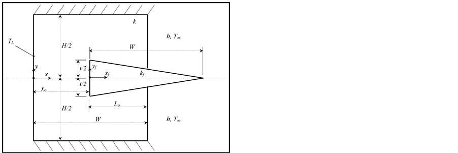
Consider a two dimensional slab wall having a uniform thickness W and height H. The x-axis is taken along the wall thickness starting from the left surface while the y-axis is aligned along its height starting from the wall center-line as shown in Figure 1(a). Next, consider an isosceles triangular fin of length W and base thickness t. The fin-base is considered to be embedded inside the wall volume as shown in Figure 1(b). The distance between the wall right surface  and the fin-base is Lo as seen from Figure 1(a). The xf-axis of the fin is directed along the fin length starting from
  while the yf-axis of the fin is aligned along the fin thickness starting from the fin center line at
  as shown in Figure 1(a). The thermal conductivity of the wall is k while that of the fin is
  where
where . Assume that heat transfer inside both materials is governed by the Fourier’s law of conduction. The two-dimensional heat diffusion equations for both volumes are:
 (1)
(1)
 (2)
(2)
where
 (3)
(3)
The quantities T, Tf, TL and T¥ are the wall temperature field, fin temperature field, left surface temperature
 (a)
(a)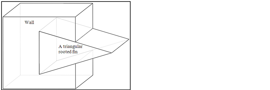 (b)
(b)and the fluid free stream temperature, respectively.
The boundary conditions of Equations (1) and (2) are taken as:
 (4a,b)
 (4c)
(4c)
 (4d)
(4d)
 (5a,b)
 (5c)
(5c)
 (5d,e)
 (6a,b)
 (6c,d)
where  and Bi (wall Biot number) are equal to the following:
 (7,8)
(7,8)
The quantity h is the convection heat transfer coefficient of the fluid stream. When the flow is made parallel to the depth of Figure 1(a), one can expect that all convective surfaces will have the same convective heat transfer coefficient. The total heat transfer rate through the left surface per unit depth represents the total heat transfer rate through the triangular rooted-finned wall. It can be evaluated from the following expression:
 (9)
(9)
The triangular rooted-finned wall effectiveness [7] is defined as the heat transfer rate through the combined system divided by that for the plain wall case. Mathematically, it is given by:
 (10)
(10)
When there is no fin, the wall right surface temperature,  , can be obtained from the following expression using the one-dimensional heat transfer model [8] :
 (11)
(11)
As such, eW can be computed from the following expression:
 (12)
(12)
Define the rooted-finned wall second performance indicator  as the ratio of the total heat transfer rate to that for the rootless fin case
 . It can be expressed as:
 (13)
(13)
2.2. Approximate Solution
In spite of the complexity of the present system,  may be bracketed by considering the present system as a piecewise one-dimensional combined system of Figure 2. The analyzed system is modeled as an arrangement of nine series and parallel different one-dimensional layers and the fluid stream medium. The thermal conductivity of layers A, B1, B2, D1 and D2 is k while that of layers C1, C2, E and the external-fin portion is
 . The dimensions of each layer are clearly seen on Figure 2. The layers C1 and C2 are connected in series with layers D1 and D2, respectively. The layers B1, B2, E, equivalent series C1-D1 layer and equivalent series C2-D2 layer are considered parallel layers. The latter equivalent parallel layers are connected in series with layer A to form

Figure 2. One dimensional piecewise model for a wall segment containing a triangular rooted-fin.
the combined wall and fin-root system. This combined system is bounded by  and
and . The right surface of the latter system located at
  is subjected to convection heat transfer over an area of
  per unit depth and conduction heat transfer through the external-fin base over an area of
  per unit depth.
Recall that the thermal resistance [8] of a given layer of thickness , height
 , unit depth length, and thermal conductivity
  is equal to:
 . The thermal resistance of the external-fin portion per unit depth is given by:
  where
where  is the efficiency of the external-fin portion.
Meanwhile, the convective thermal resistance of the right isothermal surface of the wall per unit depth is equal to: . Also, recall that the equivalent thermal resistance
  of n-series thermal resistances
  is computed from the following formula:
 . On the other hand,
  of n-parallel thermal resistances
  is obtained from the following formula:
 .
.
Finally, recall that the total heat transfer rate through the system shown in Figure 2 can be calculated from the following expression:  where
where  is the total equivalent thermal resistance between the left surface
  and the fluid free-stream on the right side of the system.
Using Equation (10) and the previous recalled formulations, the triangular rooted-finned wall effectiveness  can be bracketed into the following form:
 (14)
(14)
where S is given by:
 (15)
(15)
Using results available in any of heat transfer textbooks [8] ,  for the external-fin portion can be obtained from the following correlation:
 (16)
(16)
where Z based on the external-fin portion geometry is given by:
 (17)
(17)
3. Numerical Methodology and Validation
3.1. Numerical Methodology
The two-dimensional heat diffusion equations given by Equations (1) and (2) are coupled via their boundary conditions represented by Equations (4), (5) and (6). These systems of equations have been solved using an iterative finite volume method [9] . A third order scheme is used to discretize these equations [10] in order to reduce the numerical diffusion of errors. The selected convergence criterion requires that the sum of the energy equations residues between the current and the previous solutions be less than 10−12. Furthermore, the solution convergence has been ensured by checking the value of heat transfer rate at the left surface  and the sum of the heat transfer rate at the wall right surface
  and heat transfer rate from the fin surfaces exposed to the fluid stream. For all runs, the maximum sum of these values was found to be less than 10−5. As such, the conservation of energy was satisfied,
 . Furthermore, a fine mesh of 16,700 elements was selected. When a numerical result of one case based on that mesh was compared with the result based on a mesh of 4175 elements, the percentage difference in
  was found to be less than 0.02%. As such, solutions independent on the grid size was attained. It should be mentioned that for the situation where the interface between the fin-root and the wall is not a perfect contact surface, other methods, such as lattice Boltzmann method may be used [11] .
3.2. Validation of the Numerical Solution
Comparisons between the numerical results (2D solution) and analytical results (1D solution, Equation (14)) are shown in Figures 3 and 4. Excellent agreement are seen when  for all Bi numbers and when
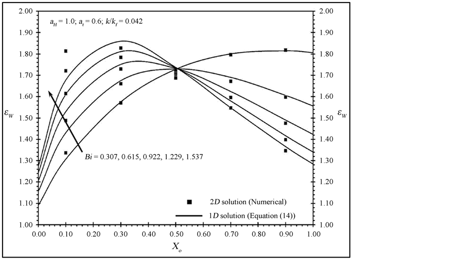
Figure 3. Effects of Xo and Bi on εw.
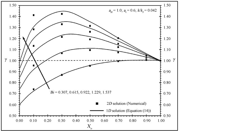
Figure 4. Effects of Xo and Bi on γ.
 if
if . This led to more confidence on the obtained results. Moreover, the following validity condition of the present 1D solution is recommended:
 (18)
(18)
The condition given by Equation (18) requires that the variation in the temperature of the wall across the root length and the variation in the temperature of the fin-root are negligible. This indicates negligible transverse conduction across the wall-root interface as compared to the axial conduction through the fin root-base. As such, the analytical 1D model given by Equation (14) is valid.
4. Discussion of the Results
4.1. Discussion of Temperature Contour Plots
Figure 5 shows temperature contours inside the different constituents of the present system at two different Biot numbers with various root-base positions. The temperature contours inside the fin-root and the wall show existence of transverse heat fluxes originated from the wall material around the root-base and directed toward the fin-root. The magnitude of these fluxes can be noticed to decrease as  increases until it is eliminated when
 . Meanwhile, it can be depicted from these plots that there can be heat fluxes originated from the fin-root close to the fin-base and directed toward the wall right surface. This is because the wall two sharp edges surrounding the fin-base have negligible conduction resistances. The previous phenomenon is noticed to disappear when
 . The two dimensional induced heat fluxes are expected to be negligible when
  as discussed earlier.
4.2. Discussion of System Effectiveness and Second Performance Indicator
As the root length increases, the wall conduction resistance decreases while the total convection resistance increases. This phenomenon is capable of minimizing the total thermal resistance of the combined system at a
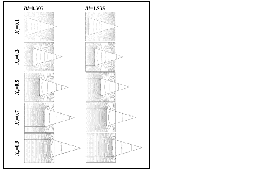
Figure 5. Effects of Xo and Bi on temperature contours for aH = 1.0, at = 0.6, and k/kf = 0.042.
specific root length. As such, the total heat transfer rate can be maximized at this length. Figure 3 demonstrates the previous phenomenon. The maximum system effectiveness seen in Figure 3 is noticed to vary with Bi as this quantity clearly alters in the total thermal resistance of the combined system. It is seen from Figure 3 that  becomes independent on Bi at a specific dimensionless fin-root length which is equal to
 . This means that both
  and
and  increase by the same extent with an increase in Bi at that specific fin-root length.
Figure 4 shows that the maximum value of  is
is  when
when . This means that the maximum heat transfer rate when
  is 44.9% above that for the rootless fin case. This maximum value occurs at a dimensionless fin-root length of
 .
.  is seen to increase as Bi increases as shown in Figure 4. Finally, Figure 6 shows the variation of the maximum combined system effectiveness
  and maximum second performance indicator
  at
at  as functions of both
  and
and  values. This figure shows that
  becomes almost independent on
  when
when . According to this figure, the maximum heat transfer rate through the triangular rooted-finned wall increases until it approches asymptotically 90% above that for the rootless fin case at
 .
.
5. Conclusions
The problem of computing heat transfer rate through a system composed of a wall and triangular rooted-fin is theoretically investigated. Appropriate forms of the coupled heat diffusion equations for the wall and the triangular rooted-fin systems were solved using a finite volume method. Approximate closed form solution for the present problem based on a wide range of engineering applications was derived. Good agreement was obtained between the numerical and the closed form solutions when the wall Biot number based on the fin-root length is smaller than the one-half. The following remarks were concluded: 1) there is a critical fin-root length that maximizes the total heat transfer rate; 2) there is a critical fin-root length that makes the total system effectiveness independent on Biot number; 3) the maximum heat transfer rate through the combined system relative to that for the rootless fin case increases as the wall Biot number increases; 4) the maximum heat transfer rate through the triangular rooted-finned wall can be at most 90% above that for the rootless fin case at ; and 5) the maximum heat transfer rate for the combined system can reach 150% above that through the plain wall at
 . Finally, it is recommended to consider triangular rooted-fins as heat transfer enhancers for highly mechanical strength structures exposed to highly convective fluid streams.
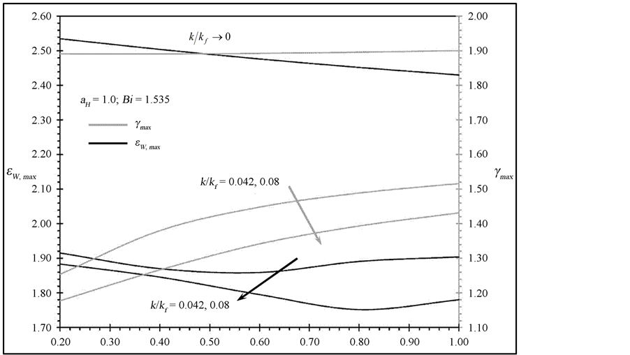
Figure 6. Effects of at and k/kf on εw,max and γmax.
Acknowledgements
The authors acknowledge the full support of this work by King Abdulaziz City for Science and Technology (KACST) under project no. 8-ENE192-3.
References
- Bergles, A.E. (1998) Handbook of Heat Transfer. 3rd Edition, McGraw-Hill, New York, 11.1-11.76.
- Kraus, A.D., Aziz, A. and Welty, J.R. (2001) Extended Surface Heat Transfer. John Wiley & Sons, Inc., New York.
- Goldstein, R.J., Ibele, W.E., Patankar, S.V., Simon, T.W., Kuehn, T.H., Strykowski, P.J., Tamma, K.K., Heberlein, J.V.R., Davidson, J.H., Bischof, J., Kulacki, F.A., Kortshagen, U., Garrick, S., Srinivasan, V., Ghosh, K. and Mittal, R. (2010) Heat transfer—A Review of 2004 Literature. International Journal of Heat and Mass Transfer, 53, 4343-4396. http://dx.doi.org/10.1016/j.ijheatmasstransfer.2010.05.004
- Goldstein, R.J., Ibele, W.E., Patankar, S.V., Simon, T.W., Kuehn, T.H., Strykowski, P.J., Tamma, K.K., Heberlein, J.V.R., Davidson, J.H., Bischof, J., Kulacki, F.A., Kortshagen, U., Garrick, S., Srinivasan, V., Ghosh, K. and Mittal, R. (2010) Heat Transfer—A Review of 2005 Literature. International Journal of Heat and Mass Transfer, 53, 4397-4447. http://dx.doi.org/10.1016/j.ijheatmasstransfer.2010.05.005
- Khaled, A.-R.A. (2008) Heat Transfer Analysis through Solar and Rooted Fins. Journal of Heat Transfer—Transactions of the ASME, 130, 74503. http://dx.doi.org/10.1115/1.2897927
- Khaled, A.-R.A. (2011) Heat Transfer Enhancements through Rooted Rectangular-and-Triangular Fins. Journal of Enhanced Heat Transfer, 18, 127-136. http://dx.doi.org/10.1615/JEnhHeatTransf.v18.i2.40
- Khaled, A.-R.A. and Al-qadi, I. (2012) Augmentation of Heat Transfer in Wall-Rooted-Fins Systems. International Journal of Numerical Methods for Heat and Fluid Flow, 22, 194-214. http://dx.doi.org/10.1108/09615531211199827
- Incropera, F.P., Dewitt, D., Bergman, T.L. and Lavine, A.S. (2011) Fundamentals of Heat and Mass Transfer. 7th Edition, John Wiley & Sons, Inc., New York.
- LeVeque, R. (2002) Finite Volume Methods for Hyperbolic Problems. Cambridge University Press, Cambridge. http://dx.doi.org/10.1017/CBO9780511791253
- van Leer, B. (1979) Towards the Ultimate Conservative Difference Scheme. V-A Second Order Sequel to Godunov’s Method. Journal of Computational Physics, 32, 101-136. http://dx.doi.org/10.1016/0021-9991(79)90145-1
- Xiong, Q., Li, B., Zhoua, G., Fanga, X., Xua, J., Wanga, J., Hea, X., Wanga, X., Wanga, L. and Gea, W. (2012) Large-Scale DNS of Gas-Solid Flows on Mole-8.5. Chemical Engineering Science, 71, 422-430. http://dx.doi.org/10.1016/j.ces.2011.10.059
Nomenclature
aH, at: (wall height, fin-root base thickness) to wall width ratio; Equations (3g) and (3h).
Bi: wall Biot number; Equation (8).
H: wall height [m].
h: convection heat transfer coefficient [W/m2∙K].
k, kf: (wall, fin) thermal conductivity [W/m∙K].
qL: triangular rooted-finned wall heat transfer rate [W].
Lo: fin-root length [m].
T, Tf: (wall, fin) temperature field [K].
TL, TR: wall (left, right) average surface temperature [K].
T¥: free stream temperature [K].
t: fin-root base thickness [m].
W: wall width (and) fin length [m].
x, xf: (wall, fin) axial coordinate [m].
Xo, xo: (dimensionless, dimensional) axial location of the fin-root base [m].
X, Xf: dimensionless (x, xf)-coordinate; Equations (3b) and (3c).
y, yf: (wall, fin) transverse coordinate [m].
Y, Yf: dimensionless (y, yf)-coordinate; Equations (3d) and (3e).
Greek Symbols
 : triangular rooted-finned wall effectiveness; Equation (10).
g: triangular rooted-finned wall second performance indicator; Equation (13).
 : fin efficiency.
q, qf : (wall, fin) dimensionless temperature; Equations (3a) and (3b).
NOTES

*Corresponding Author.