Journal of Electronics Cooling and Thermal Control
Vol.2 No.3(2012), Article ID:22370,8 pages DOI:10.4236/jectc.2012.23005
Experimental Analysis of Horizontal Ground Heat Exchanger for Northern Tunisia
Laboratory Thermal Processes, Research and Technology Centre of Energy, Hammam Lif, Tunisia
Email: *Nabiha.naili@crten.rnrt.tn
Received June 26, 2012; revised July 28, 2012; accepted August 20, 2012
Keywords: Horizontal Ground Heat Exchanger; Geothermal; Hot Climate; Energy Efficiency
ABSTRACT
The aim of this study is first to evaluate the Tunisian geothermal energy and second to test the performance of horizontal ground heat exchanger. An experimental set-up has been constructed for climatic condition of Borj Cedria located in the north of Tunisia for space cooling. Results obtained during experiment were presented and discussed. The ground temperature at several depths was measured, the overall heat transfer coefficient (U) was determined. To evaluate the system efficiency, the energy analysis was applied; the energy efficiency was found to range from 14% to 28%. The heat exchange rate was quantified, the pressure losses were calculated. The total heat rejected by using the ground heat exchanger (GHE) system was compared to the total cool requirements of a tested room with 12 m2 surface. The results showed that the GHE, with 25 m of length buried at 1 m depth, covers 38% of the total cool requirement of the tested room. This study showed that the ground heat exchanger provide a new way of cooling buildings, it also showed that Tunisia have an important thermal potential. This favorable circumstance allows Tunisia to be a pioneer in the exploitation of geothermal energy for the installation of ground source heat pump systems.
1. Introduction
Tunisia, like other countries in the world, benefits from numerous natural geothermal sources. We can notice that this potential is not largely used and that, with the evolution of energy prices, geothermal energy as other renewable sources of energy must now considered with a new interest especially in the building heating and cooling.
Geothermal energy as environmentally friendly energy source with wide range of applications such as for space heating and cooling, hot water supply and applications in the agricultural field has been used in practical engineering. The well-known application is for space heating and cooling in residential and commercial buildings with using ground source heat pump system [1].
Ground-source heat exchangers provide a new and clean way of heating buildings in the world. They make use of renewable energy stored in the ground, providing one of the most energy-efficient ways of heating buildings. They are suitable for a wide variety of building types and are particularly appropriate for low environmental impact projects. They do not require hot rocks (geothermal energy) and can be installed in most of the world, using a borehole or shallow trenches or, less commonly, by extracting heat from a pond or lake. Heat collecting pipes in a closed loop, containing water (with a little antifreeze) are used to extract this stored energy, which can then be used to provide space heating and domestic hot water [2].
In the last decade the development of GHE technology has registered a great interest worldwide. The first working GSHP prototype was installed in the USA in 1945 as a demonstration device and it succeeded in showing clearly the big advantages of such an innovative solution. The ground heat exchanger (GHE) is an important part of the ground source heat pump (GSHP), it consists of a length of pipe buried at reasonable depth below the ground surface. There are many basic types of ground loop systems [3-6]. The GHE is best depends on the climate, soil conditions, available land, and local installation costs at the site.
In the open literature, many researches works have been conducted, modeling and testing of ground coupled heat pump systems [7-18].
Esen et al. [7] have tested the performance of an air-conditioning system formed by a ground coupled heat pump with two different depths for ground exchanger: 1 m and 2 m. Their experience showed that the ground exchanger performance increases with the depth (2.5 for 1 m and 2.8 for 2 m). They have also carried out a comparative economic evaluation [9]. Zhao et al. [10] indicate that heat transfer mainly happens near the outer wall of coaxial GHE and inclines to stabilization at far-field, they also have concluded that the inlet temperature, initial temperature of porous medium and the flow rate are major factors affecting heat transfer. Cui et al. [12] have developed a finite element numerical model to simulate hybrid ground-coupled heat pump with domestic hot water heating (DHW). Authors have concluded that The HGCHP can offer almost 95% of total DHW demand in this case study along with about 70% energy saving compared to the electric heater. Bi et al. [17] have employed a two-dimensional cylindrical coordinate system to model a ground heat exchanger. A CFD simulations have been carried out by Congedo et al. [18] to analyses three main geometries of horizontal ground heat exchangers: linear, helical and slinky. In their study, the authors have concluded that the most important parameter for the heat transfer performance of the system is the thermal conductivity of the ground around the heat exchanger, they have also showed that the choice of the velocity of the heat transfer fluid inside the tubes is a key factor for heat transfer performance for all the arrangements.
In this paper, an experimental set-up was constructed for climatic condition of Borj Cedria localized in the north of Tunisia. The aims of this study are first to evaluate the Tunisian geothermal energy and second to test the performance of horizontal ground heat exchanger with 25 m of length buried at 1 m depth.
2. Experimental Set-Up
2.1. Description of the System
The schematic arrangement of the experimental system is given in Figure 1. The experimental set-up consists mainly of two units: the ground heat exchanger (GHE), which its photograph is chow in Figure 2 and the heat pump. The GHE consists of a polyethylene tube, 16 mm in internal diameter, buried at 1 m depth. The distance between tubes is 0.3 m to minimize the interference between them. An air-liquid Clivet type heat pump was used to design tests. The specifications and characteristics of the components of the experimental system are given in Table 1.
2.2. Measurements Procedure
The experimental approach consists to fix the water temperature and mass flow rates at the inlet of the exchanger, when the temperature in the outlet side of the exchanger is stabilized (steady-state), we note the outlet temperature, which used to accurate the experimental analysis. Various tests were carried out in a range of
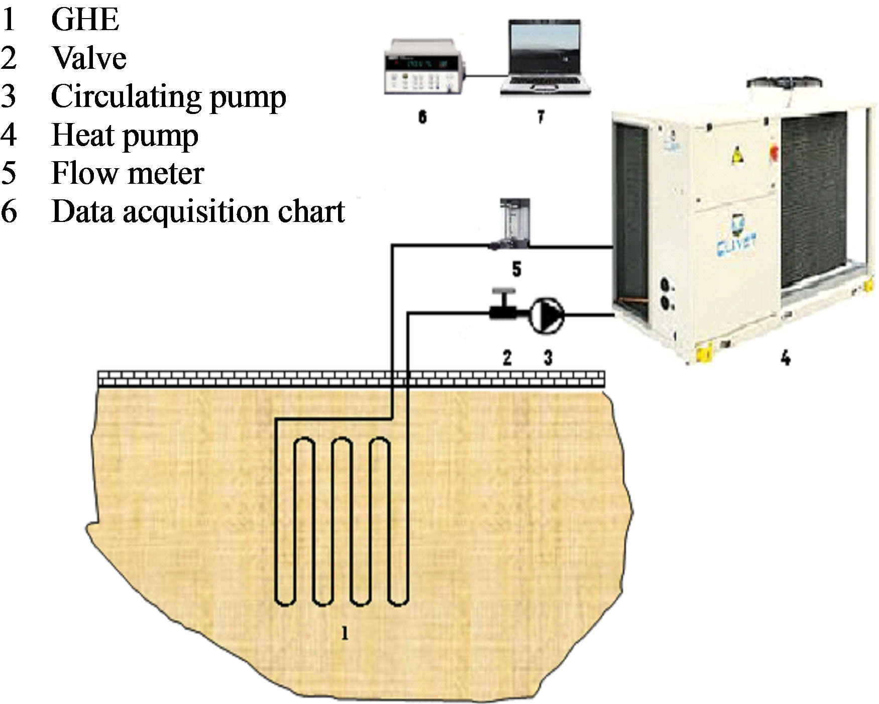
Figure 1. Schematic of the experimental system.

Figure 2. View of the GHE buried at 1 m depth.
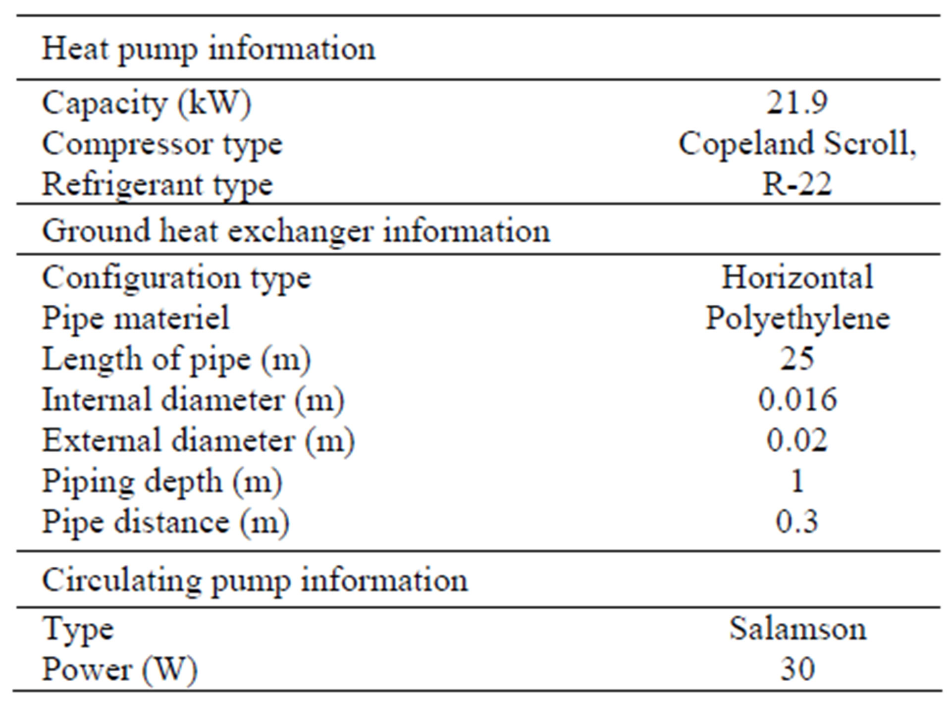
Table 1. Experimental parameters.
mass flow rate between 0.06 and 0.2 kg·s−1.
In the present study, the temperature and masse flow rates, were measured by appropriate instruments explained below:
• The inlet, outlet temperatures of GHE and the ground temperature were measured by using thermocouples.
• The water mass flow rate was measured by a rotameter.
• The pressures losses were determined with empirical formula in the literature [19].
All measured temperatures were recorded by using a multi-channel data-logger type HP, which were stocked in a PC. The experimental results were obtained from the ground-source heat pump-system in the cooling season of 2010-2011.
2.3. Uncertainty Analysis
Uncertainty analysis is needed to prove the accuracy of the experiments. In this study, errors came from the sensitiveness of equipment and measurements explained previously. First; errors due to measurement of temperature are: 1) sensitiveness of data acquisition system, about ± 0.1%˚C; 2) measurement error is ±0.2% and 3) sensitiveness of the thermocouple is ±0.1%˚C. The sensitiveness was obtained from a catalog of the instruments. Second, errors came from the measurement of the flow rate: 1) the sensitiveness of the flow meter is about ±0.1% and 2) errors due to measurement are about ±0.1%. In total, errors of measurement of the flow rate are about ±0.2%.
3. Soil and Climate Properties
3.1. Soil Characteristics
In geothermal systems applications, deposition or extraction of thermal energy from the ground is accomplished by using a ground heat exchanger (GHE). The operation of this heat exchanger induces a simultaneous heat and moisture flow in the surrounding soil. The transfer of heat between the GHE and adjoining soil is primarily by heat conduction and to a certain degree by moisture migration. Therefore, it depends strongly on the soil type, temperature and moisture gradients [20].
The soil thermal diffusivity (a) is a defined property and is the ratio of the thermal conductivity (l) and the heat capacity (rC) (Table 2). Therefore, the three soil properties, l, r and C must be known or estimated to predict the thermal behavior of GHEs [21]. Obtaining accurate values for the thermal properties of the soil requires a detailed site survey. In order to estimate the thermal properties of granular soils (sand, clay, silt), it is necessary to determine the sand and clay content, dry density and moisture content [22].
3.2. Weather Data
The experimental set-up was established at the Research
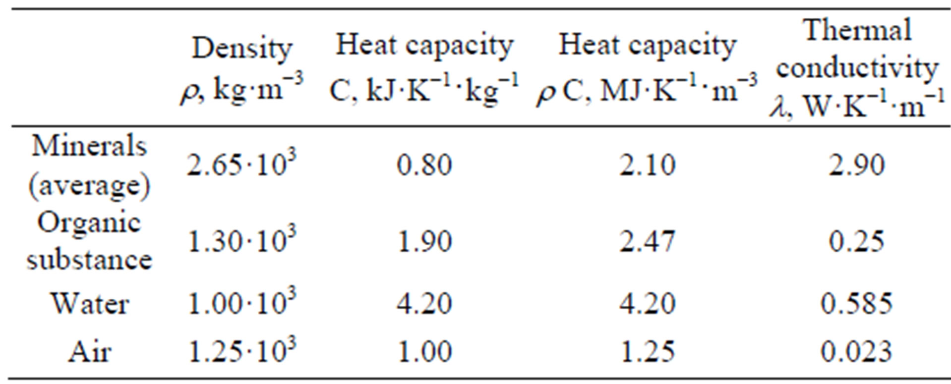
Table 2. Thermal properties and physics of the principal components of the ground [23].
and Technology Center of Energy, Borj Cedria, northern Tunisia, latitude 36.83 and longitude 10.23. The climatic conditions of Borj Cedria for average values (monthly average minimum, maximum and mean outdoor temperature, the monthly averages of relative humidity, wind velocity, solar radiation and Average soil temperature at 1 m depth for the cooling season) are given in Table 3.
4. Analysis
In this study we will consider only the heat exchange which is making in stationary regime. The heat transfer inside a pipe is makes by forced convection. When we consider an infinitesimal element dx of a tube in the coolant flow direction, the heat exchange rate Qe is given by the following expression:
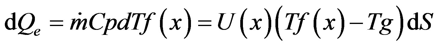 (1)
(1)
By admitting that the overall heat transfer coefficient remains constant all along the exchanger, (U(x) = U), after integration, the preceding equation gives
 (2)
(2)
where Ti and To are the exchanger inlet and outlet temperature respectively.
The heat exchange rate Qe was calculated from the following equation:
(1) and (2) give
 (3)
(3)
where

Table 3. The climatic conditions of Borj Cedria over cooling season of 2010-2011.
represents a log mean temperature difference DTLM, so the heat exchange rate can be puts as follows
 (4)
(4)
To evaluate the performance of the GHE, we often use the energy efficiency concept. It is defined by the ratio of the really heat exchange rate (Qe) and the theoretically possible of maximum heat exchange rate (QMax), it is expressed by:
 (5)
(5)
with
 (6)
(6)
The exchanger energy efficiency is written then:
 (7)
(7)
The pressure losses must be calculated in order to be able to balance the various criteria the ones compared to the others. For the calculation of the pressure losses, we must calculate the linear and singular pressure losses
 (8)
(8)
The linear pressure loss for a flow in a rectilinear control is determined in the following way [24]:
 (9)
(9)
The calculation of the loss ratio of load (L) depends on the nature of the flow, laminar or turbulent. This last gives place to more significant pressure losses. The singular pressure loss is defined by [24]:
 (10)
(10)
5. Results and Discussions
The ground temperature constitutes an essential data in the installation of GHEs. To determine the ground temperature, we installed in different ground levels, thermocouples which are connected to an acquisition system data. The ground temperature results at various depths (d) measured in summer (21-23 June 2010) is shown in Figure 3, we can note that the ground sees its temperature changes decreased exponentially with depth. This decrease diminished as the ground depth increases because the high thermal inertia of the ground.
Measurements show that the ground temperature below a certain depth remains relatively constant. The temperature at 1m depth is about 23˚C while the outdoor temperature is about 37˚C. When the temperature at 1m depth was compared with the outdoor temperature, we established that Tunisia benefits from an important natural geothermal source. Figure 4 shows the curves of the heat exchange rate versus the log mean temperature difference (DTLM) for the following flows rate: 0.06, 0.08, 0.1, 0.12 and 0.16 kg·s–1 and for a variety of inlet temperature ranging between 30˚C and 50˚C.
The experimental variation of the heat exchange rate (Qe) versus the log mean temperature difference (DTLM), is linear. The respective slopes of these lines brought back to the unit of surface are, in steady state, the overall heat transfer coefficient, U, of the exchanger.

Figure 3. Soil temperature at several depths 21-23 June 2010.
 (a)
(a)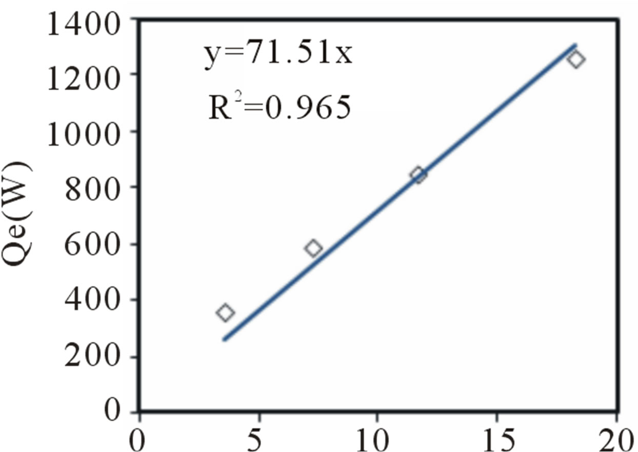 (b)
(b)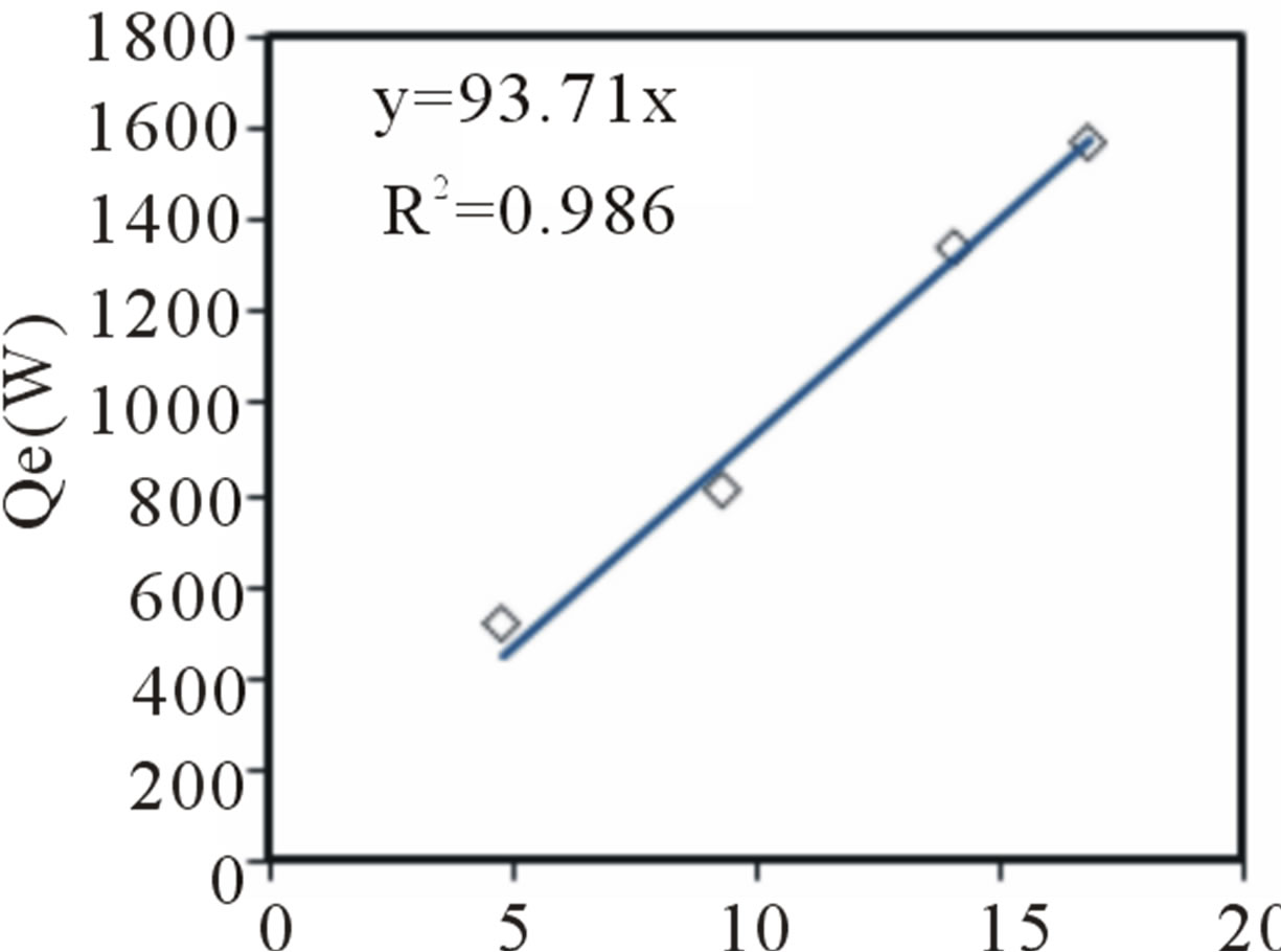 (c)
(c)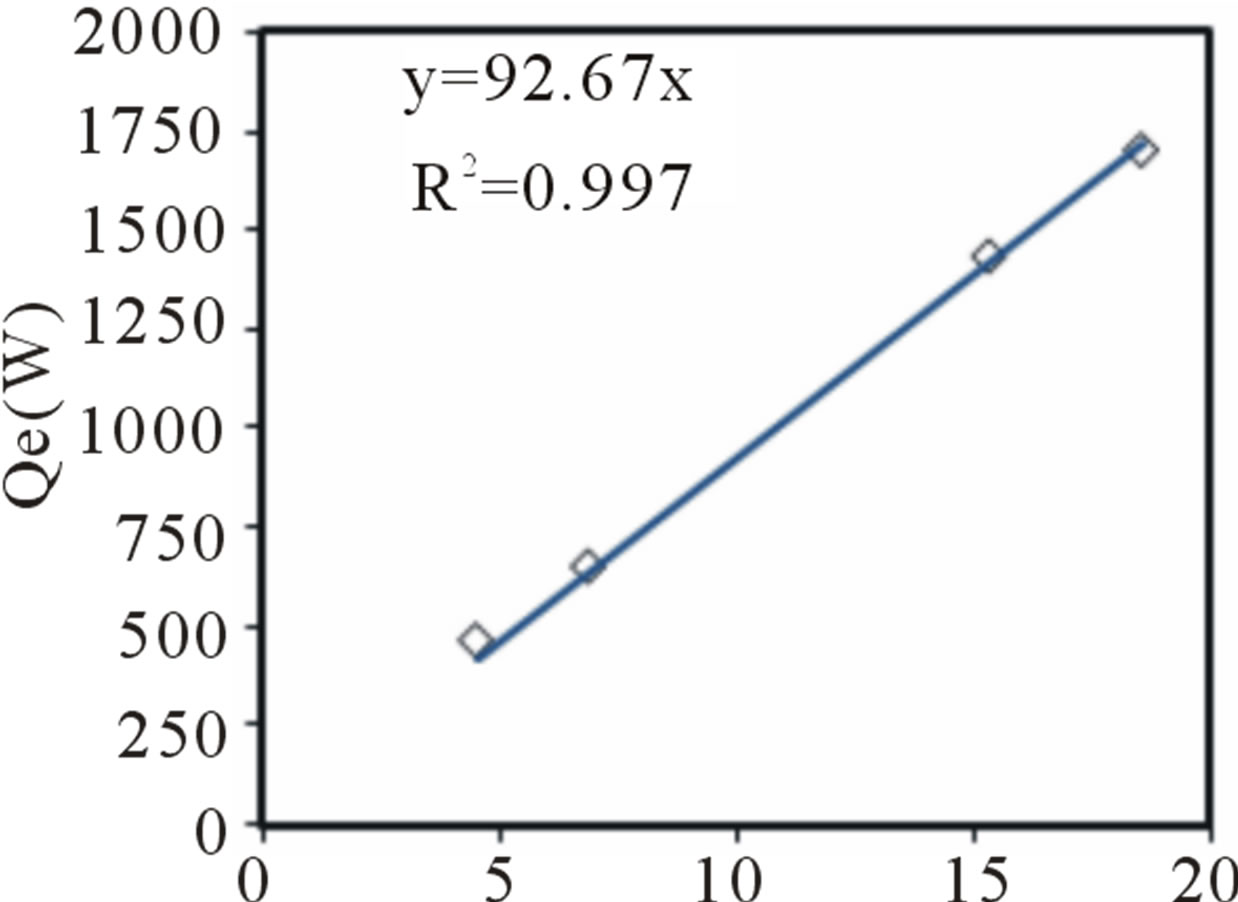 (d)
(d)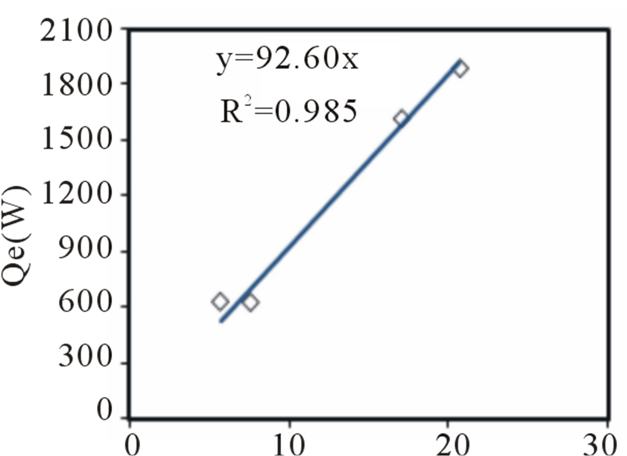 (e)
(e)
Figure 4. Heat exchange rate versus the log mean temperature difference for the following flow rates (a) 0.06 kg·s–1; (b) 0.08 kg·s–1; (c) 0.1 kg·s–1; (d) 0.12 kg·s–1; (e) 0.16 kg·s–1.
The overall heat transfer coefficient values are regrouped in Table 4. We can conclude from Table 4 that the overall heat transfer coefficient, U, increases versus the mass flow rate. This increase is not linear. It is slowed down by the pressure losses. The overall heat exchange coefficient reached, during experiments, a maximum value of 59.02 W·m−2·˚C−1 for a 25 m of exchanger length and mass flow rate about 0.12 kg·s−1. The use of the exchanger with lower flows decreases notably the overall heat transfer coefficient.
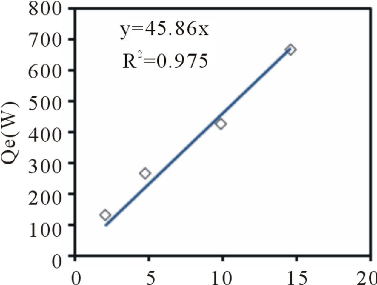
The use of the ground coupled heat pump aims essentially to have the maximum of the heat exchange rate, this quantity depends from many parameters. In our study we try to test the effect of the water coolant flow rate on this quantity, so we represent in Figure 5 the heat exchange rate Qe variation versus mass flow rate.
It is noted that the heat exchange rate tends towards a limiting value about 650 W obtained for a water mass flow rate about 0.12 kg·s–1. Thus 0.12 kg·s–1 is the optimal mass flow rate. Indeed, any increase in the flow of water coolant beyond this value, does not affect the heat exchange rate. We can also concluded from this figure that the heat exchange rate, when the temperature in the outlet side of the exchanger is stabilized (steady-state) and for the masse flow rate about 0.12 kg·s–1, is about 26 W/m witch reflects the importance of geothermal energy in Tunisia.
The energy efficiency of the ground heat exchanger is determined by the NTU, the results are shown in Figure 6. It is noticed from this figure that the energy efficiency increases with NTU, which ranging from 14.3% to 28.4%. Indeed, the NTU determines the residence time of the water on the heat exchanger surface and thus also the amount of heat that it can absorbs by the ground. Consequently when the NTU increases the residence time of the water in the heat exchanger increases, thus the outlet temperature increases witch increase the energy efficiency.
To calculate the pressure loss we must first calculate the Reynolds number Re (Table 5) to estimate the type of flow for the various flows used.
It is seen, in the Table 5, that for the range of the flows which we considered in our experimental study, it is difficult to obtain a laminar flow. We will thus consider for the continuation the pressure loss for a turbulent flow. In this case, the loss ratio of load can be determined by the Blasius relation:
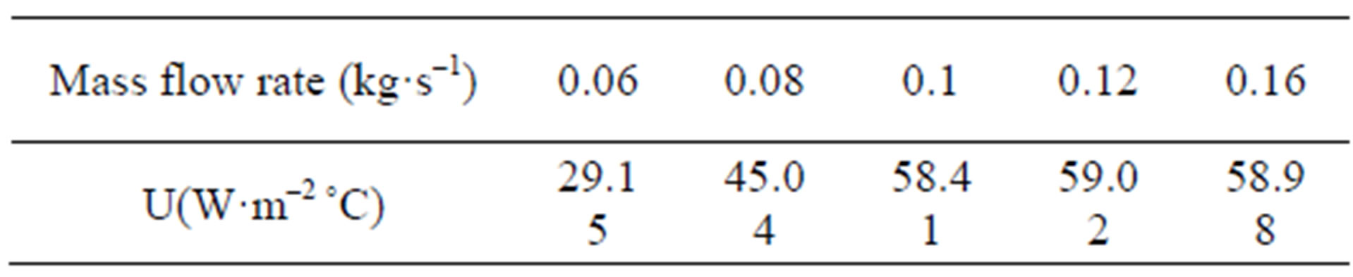
Table 4. The overall heat transfer coefficient.

Figure 5. Heat exchange rate versus the flow rate for Ti = 30˚C.
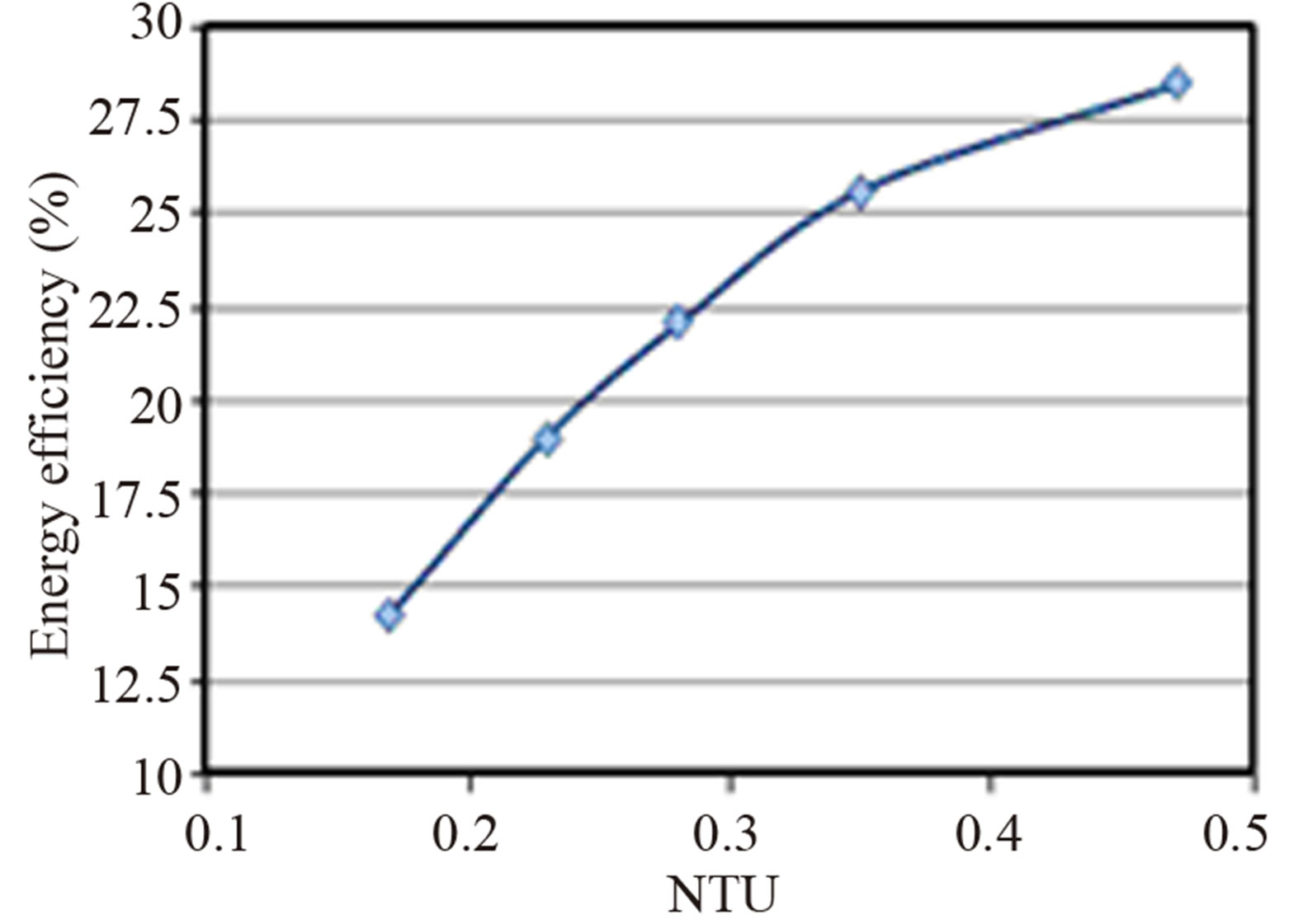
Figure 6. Energy efficiency versus NTU.
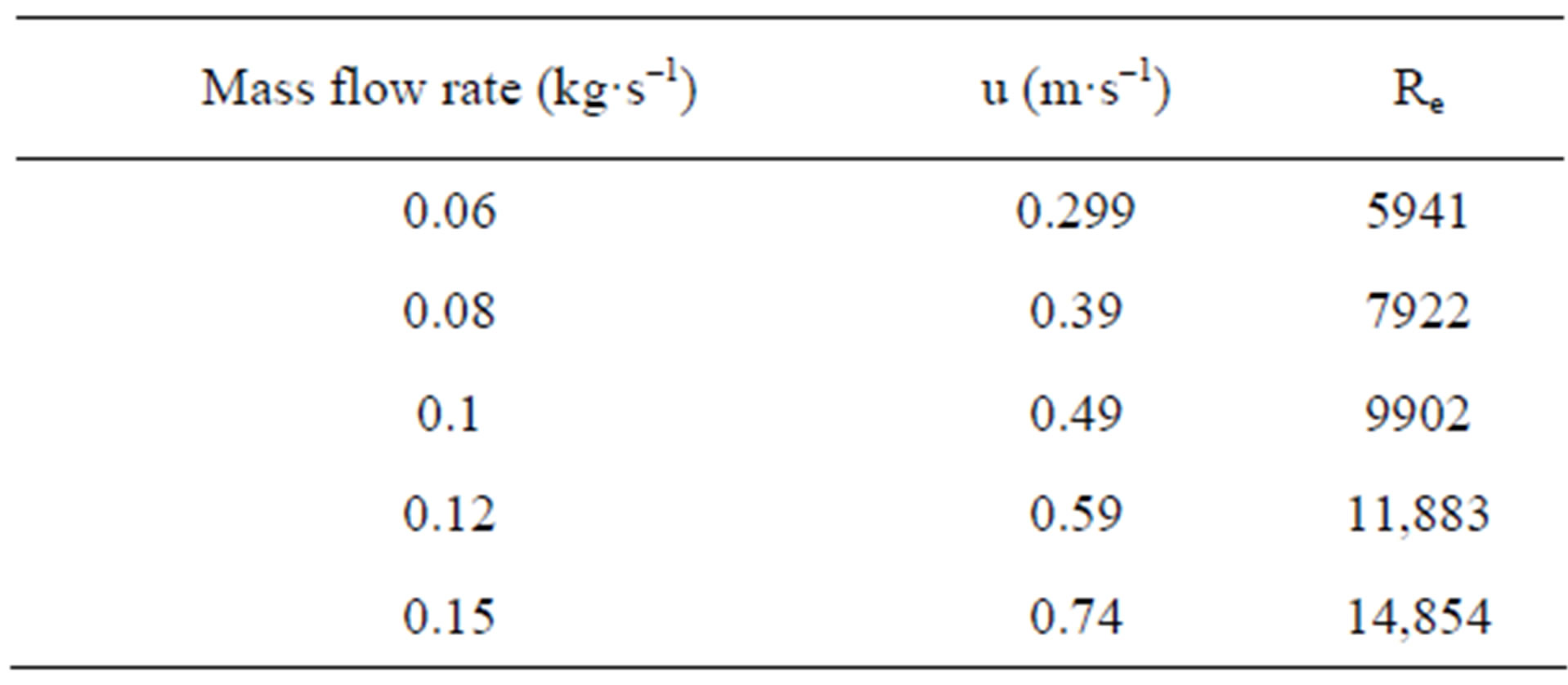
Table 5. Calculation of the Reynolds number.
In Figure 7 we represent the variation of the pressure loss versus mass flow rate. It is noticed that more the mass flow rate increases more the pressure loss increases too (Equations (9) and (10)). This is due to the several accidents met by the liquid coolant inside the exchanger. For the experimental masse flow rate (0.12 kg·s–1) the pressure loss is about 8.43 kPa.
This result is compatible with the experimental and numerical study published in the literature (Missirlis et al. [19]).
The total heat rejected by using the HGSHE system was compared to the total cool requirements of a tested room (4 m × 3 m × 3 m), which the temperature of thermal comfort under cover is 26˚C in summer, in climatic condition of cooling season of Tunisia. We established that for the optimal flow rate procurement found (0.12 kg·s–1), the maximum thermal power extracted from the ground is about 650 W. this value represents 38.5% of the cooling loads of the room test. The results showed that Tunisia have an important thermal potential. This favourable circumstance allows Tunisia to be a pioneer in the exploitation of geothermal energy for the installation of ground source heat pump systems.
6. Conclusions
In the present study horizontal ground heat exchanger was buried at 1 m and tested in the Research and Technology Center of Energy, Tunisia. The following conclusions can be drawn from this study:
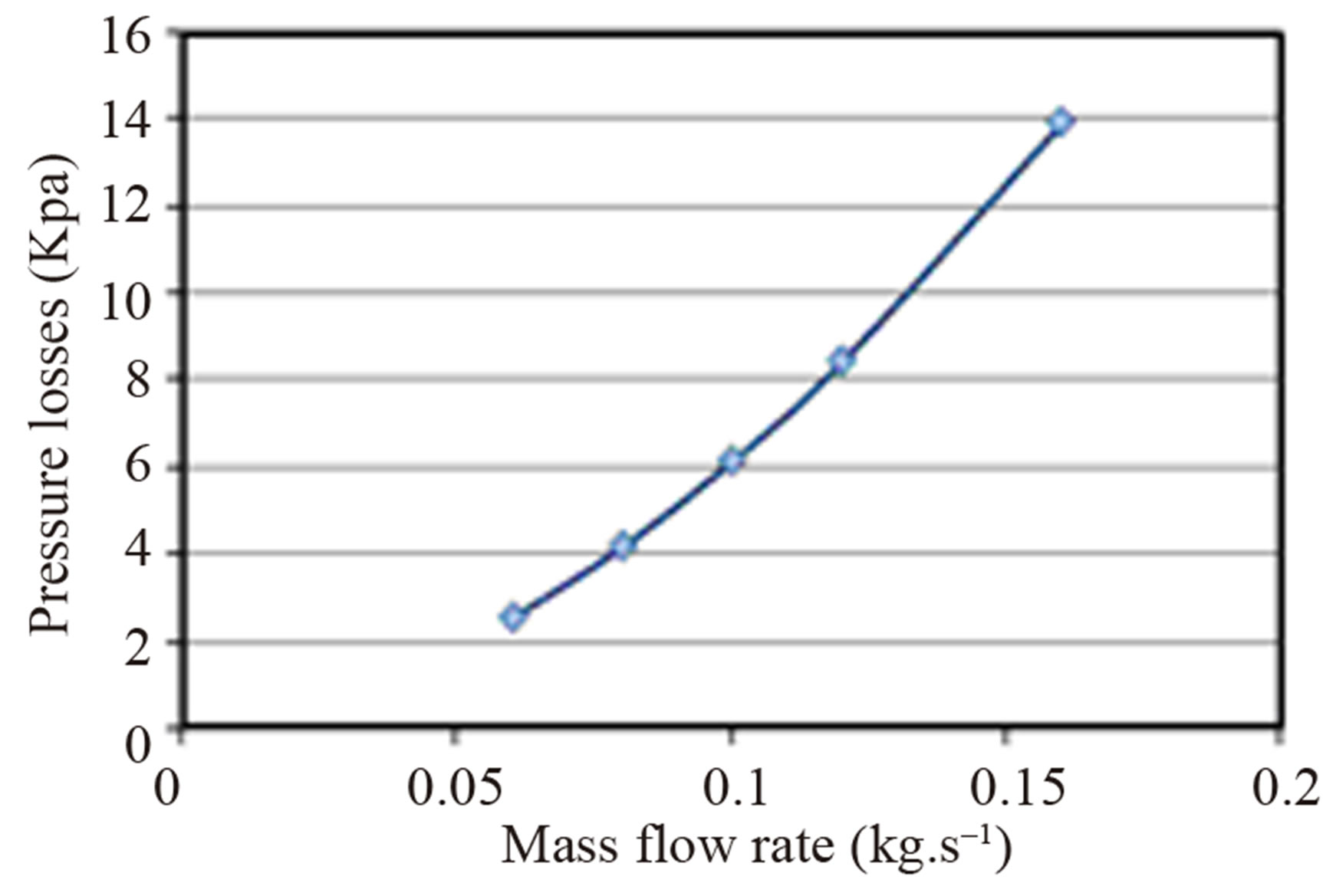
Figure 7. Pressure loss versus mass flow rate.
* Thermal potential in Tunisia offers a good exploitation of horizontal ground source heat exchanger (HGSHE), indeed the experimental ground temperature shows that, at sufficient depth, it is always lower than that of the outside air in summer. It can be seen also that the ground temperature is nearly constant below a depth of 1 m;
* The energy efficiency for the GSHE system considered are found to range from 14.3% to 28.4%;
* The heat exchange rate, when the temperature in the outlet side of the exchanger is stabilized (steady-state), is about 26 W/m witch reflects the importance of surface geothermal energy in Tunisia;
* The pressure loss increase with the mass flow rate, for the optimal mass flow rate obtained (0.12 kg·s–1) the pressure loss is about 8.43 kPa;
* The GHE, with 25 m of length buried at 1m depth, covers 38.5% of the total cool requirement of a tested room with 12 m2 surface.
7. Acknowledgements
The authors would like to thank the Laboratoire des Procédés Thermiques (LPT) for financially supporting the project and for supplying some useful data.
REFERENCES
- Jalaluddin and A. Miyara, “Thermal Performance Investigation of Several Types of Vertical Ground Heat Exchangers with Different Operation Mode,” Applied Thermal Engineering, Vol. 33-34, 2012, pp. 167-174. doi:10.1016/j.applthermaleng.2011.09.030
- A. M. Omer, “Ground-Source Heat Pumps Systems and Applications,” Renewable and Sustainable Energy Reviews, Vol. 12, No. 2, 2008, pp. 344-371. doi:10.1016/j.rser.2006.10.003
- G. Axelsson, “Sustainable Geothermal Utilization—Case Histories; Definitions; Research Issues and Modelling,” Geothermics, Vol. 39, No. 4, 2010, pp. 283-291. doi:10.1016/j.geothermics.2010.08.001
- X. H. Xu, S. W. Wang, J. B. Wang and F. Xiao, “Active Pipe-Embedded Structures in Buildings for Utilizing LowGrade Energy Sources: A Review,” Energy and Buildings, Vol. 42, No. 10, 2010, pp. 1567-1581. doi:10.1016/j.enbuild.2010.05.002
- G. Florides and S. Kalogirou, “Ground Heat Exchangers—A Review of Systems, Models and Applications,” Renewable Energy, Vol. 32, No. 15, 2007, pp. 2461-2478. doi:10.1016/j.renene.2006.12.014
- D. Milenić, P. Vasiljević and A. Vranješ, “Criteria for Use of Groundwater as Renewable Energy Source in Geothermal Heat Pump Systems for Building Heating/ Cooling Purposes,” Energy and Buildings, Vol. 42, No. 5, 2010, pp. 649-657. doi:10.1016/j.enbuild.2009.11.002
- H. Esen, M. Inalli, M. Esen and K. Pihtili, “Energy and Exergy Analysis of a Ground-Coupled Heat Pump System with Two Horizontal Ground Heat Exchangers,” Building and Environment, Vol. 42, No. 10, 2007, pp. 3606-3615. doi:10.1016/j.buildenv.2006.10.014
- U. Eicker and C. Vorschulze, “Potential of Geothermal Heat Exchangers for Office Building Climatisation,” Renewable Energy, Vol. 34, No. 4, 2009, pp. 1126-1133. doi:10.1016/j.renene.2008.06.019
- H. Esen, M. Inalli and M. Esen, “A Techno-Economic Comparison of Ground-Coupled and Air-Coupled Heat Pump System for Space Cooling,” Building and Environment, Vol. 42, No. 5, 2007, pp. 1955-1965. doi:10.1016/j.buildenv.2006.04.007
- J. Zhao, H. J. Wang, X. G. Li and C. S. Dai, “Experimental Investigation and Theoretical Model of Heat Transfer of Saturated Soil around Coaxial Ground Coupled Heat Exchanger,” Applied Thermal Engineering, Vol. 28, No. 2-3, 2008, pp. 116-125.
- C. A. De Swardt and J. P. Meyer, “A Performance Comparison between an Air-Source and a Ground-Source Reversible Heat Pump,” International Journal of Energy Research, Vol. 25, No. 10, 2001, pp. 899-910. doi:10.1002/er.730
- P. Cui, H. Yang and Z. Fang, “Numerical Analysis and Experimental Validation of Heat Transfer in Ground Heat Exchangers in Alternative Operation Modes,” Energy and Buildings, Vol. 40, No. 6, 2008, pp. 1060-1066. doi:10.1016/j.enbuild.2007.10.005
- H. Demir, A. Koyun and G. Temir, “Heat Transfer of Horizontal Parallel Pipe Ground Heat Exchanger and Experimental Verification,” Applied Thermal Engineering, Vol. 29, No. 2-3, 2009, pp. 224-233. doi:10.1016/j.applthermaleng.2008.02.027
- A. Negiz, M. A. Hastaoglu and R. A. Heidemann, “ThreeDimensional Transient Heat Transfer from a Buried Pipe —I. Laminar Flow,” Chemical Engineering Science, Vol. 48, No. 20, 1993, pp. 3507-3517. doi:10.1016/0009-2509(93)85006-B
- A. Negiz, M. A. Hastaoglu and R. A. Heidemann, “ThreeDimensional Transient Heat Transfer from a Buried Pipe: Solidification of a Stationary Fluid,” Numerical Heat Transfer, Vol. 28, No. 2, 1995, pp. 175-193. doi:10.1080/10407789508913740
- S. Thiers and B. Peuportier, “Modélisation Thermique d’un échangeur Air/Sol Pour le Rafraîchissement des Bâtiments,” Journée Thématique SFT-IBPSA Froid Solaire et Confort d’été, 2007, Aix-les-Bains.
- Y. H. Bi, L. G. Chen and C. Wu, “Ground Heat Exchanger Temperature Distribution Analysis and Experimental Verification,” Applied Thermal Engineering, Vol. 22, No. 2, 2002, pp. 183-189. doi:10.1016/S1359-4311(01)00073-4
- P. M. Congedo, G. Colangelo and G. Starace, “CFD Simulations of Horizontal Ground Heat Exchangers: A Comparison among Different Configurations,” Applied Thermal Engineering, Vol. 33-34, 2012, pp. 24-32. doi:10.1016/j.applthermaleng.2011.09.005
- D. Missirlis, S. Donnerhack, O. Seite, C. Albanakis, A. Sideridis, K. Yakinthos and A. Goulas, “Numerical Development of a Heat Transfer and Pressure Drop Porosity Model for a Heat Exchanger for Aero Engine Applications,” Applied Thermal Engineering, Vol. 30, No. 11-12, 2010, pp. 1341-1350. doi:10.1016/j.applthermaleng.2010.02.021
- W. H. Leong, V. R. Tarnawski and A. Aittomaki, “Effect of Soil Type and Moisture Content on Ground Heat Pump Performance,” International Journal of Refrigeration, Vol. 21, No. 8, 1998, pp. 595-606. doi:10.1016/S0140-7007(98)00041-3
- J. E. Bose, J. D. Parker and F. C. McQuiston, “Design/ Data Manual for Closed-Loop Ground-Coupled Heat Pump Systems,” American Society of Heating, Refrigerating and Air-Conditioning Engineers, Atlanta, 1985.
- S. P. Kavanaugh and K. Rafferty, “Ground-Source Heat Pumps: Design of Geothermal Systems for Commercial and Institutional Buildings,” American Society of Heating, Refrigerating and Air-Conditioning Engineers, Chiba, 1997.
- M. Hazami, “Étude Expérimentale et Numérique du Phé- nomène de Stockage et de Déstockage de L’énergie Sensible en Utilisant un Echangeur Capillaire en Polypropylène,” Thèse de Doctorat, Faculté des Sciences de Tunis, Tunis, 2008.
- I. E. IdelCik, “Mémento des Pertes de Charges: Coefficients de Pertes de Charges Singulières et de Pertes de Charge par Frottement,” Traduit par M. Meury, Editions Eyrolles, Saint-Germain, Paris, 1986.
Nomenclature
NOTES
*Corresponding author.