Journal of Electronics Cooling and Thermal Control
Vol.1 No.3(2011), Article ID:9224,7 pages DOI:10.4236/jectc.2011.13005
Experimental Study of Jet Nanofluids Impingement System for Cooling Computer Processing Unit
1Thermo-Fluids and Heat Transfer Enhancement Lab, Department of Mechanical Engineering, Faculty of Engineering, Srinakharinwirot University, Ongkharak, Thailand
2Fluid Mechanics, Thermal Engineering and Multiphase Flow Research Lab, Department of Mechanical Engineering, King Mongkut’s University of Technology Thonburi, Suksawas, Bangkok, Thailand
E-mail: *paisarnn@swu.ac.th
Received September 20, 2011; revised November 15, 2011; accepted November 25, 2011
Keywords: Jet Impingement, Nanofluids Cooling, Cooling CPU, Mini-Rectangular Fin Heat Sink
Abstract
An experimental investigation of the jet nanofluids impingement heat transfer characteristics of mini-channel heat sink for cooling computer processing unit of personal computer is performed. The experiments are tested under the real personal computer operating conditions: no load and full load conditions. The experiments are performed for the following ranges of the parameters: coolant flow rate varies from 0.008 to 0.020 kg/s, the nozzle diameter is set to 1.00, 1.40, 1.80 mm, the distance nozzle-to-fins tip is 2.00 mm, the channel width of the mini-channel heat sink is 1.00 mm. The nanofluids with suspending of TiO2 particles in base fluid are used as a working fluids. It was observed that the average CPU temperatures obtained from the jet nanofluids impingement cooling system are 3.0%, 6.25% lower than those from the jet liquid impingement and from the conventional liquid cooling systems, respectively. However, this cooling system requires higher energy consumption.
1. Introduction
In order to ensure reliable operation, the PCs or electronics devices must be operated in the specific temperature ranges which the exceeding maximum allowable temperature is the serious problem of these devices. There are many techniques to dissipate the generated heat. The development of the miniaturized technology, mini and micro-components has been introduced as one of heat transfer enhancement techniques. The study of a single phase heat transfer of the various geometrical heat sinks for cooling electronic devices are reported by Zhange et al.,[1]; Yu [2]; Peles [3]; Kosar and Peles [4]; Yakut et al. [5]; Mohamed [6]. Didarul [7] investigated the heat transfer and fluid flow characteristics of finned surfaces. Chein and Chuang [8] applied the thermoelectric with microchannel heat sink by using nanofluids as coolant for cooling electric components. Jeng and Tzeng [9] experimentally studied the pressure drop and heat transfer of a square pin-fin array. These studies indicated that the various geometrical heat sinks are possible for cooling electronics devices.
The most frequently used coolants in the heat transfer devices study are air, water, and fluoro-chemicals. However, the heat transfer capability is limited by the working fluid transport properties. One of the methods for the heat transfer enhancement is the application of additives to the working fluids to change the fluid transport properties and flow features. Therefore, in order to further enhance thermal performance of heat transfer devices, the use of nanofluids is proposed. The numerous papers presented on the single phase convective heat transfer of nanofluids, boiling heat transfer of nanofluids and heat transfer enhancement using nanofluids are continuously reviewed by Duangtongsuk and Wongwises [10]; Trisaksri and Wonwises [11]; Godson et al. [12]. However, improving the cooling performance had been continuously performed by using the jet liquid impingement technique. Thermal performance of a pin-fin heat sink with various geometrical with impingement cooling was considered by Kobus and Oshio [13]; Li et al. [14]. Geedipalli et al. [15] simulated the combination heating of food using microwave and jet impingement by coupling Maxwell’s equation. Sung and Mudawar [16,17] studied the jet impingement single-phase and two-phase heat transfer characteristics. Reasonable agreement was obtained between the predicted results and the measured data. Koseoglu and Baskaya [18] used a Laser Doppler Anemometry to observe the jet flow field and turbulence on heat transfer characteristics. The jet heat transfer enhancement from a flat surface was simulated by Katti and Prabhu [19]; Kanna and Das [20]; Cirillo and Isopi [21]. Goodro et al. [22] considered effects of the hole spacing on the spatially-resolved jet array impingement heat transfer. Jeng et al. [23] and Hewakandamby [24] investigated the jet air flow and heat transfer behaviors of the rotating heat sink and oscillation impinging jet. Nguyen et al. [25] studied the enhanced heat transfer with of nanofluids in a confined and submerged impinging jet on a flat, horizontal and circular heated surface. Koseoglu and Baskaya [26] experimentally and numerically investigated the impinging jet heat transfer. Chang et al. [27] studied the jet-array impingement heat transfer in a concentric annular channel with rotating inner cylinder. Sharif and Banerjee [28] applied the k-e turbulence model to analyze the heat transfer of the confined slot-jet impingement on a moving plate. Whelan and Robinson [29] used the jet liquid impingement for cooling the electronics devices. Several studies showed that thermal conductivity of the nanofluids is higher than that of the base fluids and therefore great potential for the enhancement of heat transfer.
As mentioned above, the numerous papers presented the study on the heat transfer and pressure drop in the miniand micro-channel, nanofluids heat transfer enhancement, jet impingement heat transfer characteristics. However, only one work [25] reported the passive and active heat transfer enhancement techniques by using the jet nanofluids impingement heat transfer characteristics of the heat sinks. Therefore, the present work focus on the experimental study of the jet nanofluids impingement heat transfer characteristics of the mini-rectangular fin heat sink for cooling computer processing unit (CPU) of personal computer (PC) based on the real operating conditions of PC. This is because it has an excellent chemical and physical stability, a safe material for human, produced commercially available products, and cheap. The TiO2 nanoparticles are used in the present experiments. The results obtained from the jet nanofluids impingement cooling system are compared with those from the jet liquid impingement and the conventional liquid cooling systems.
2. Experimental Apparatus and Method
2.1. Test Loop
This paper primary tries to investigate the jet nanofluids impingement heat transfer of the mini-rectangular channel heat sinks for CPU of PC. A schematic diagram of the experimental apparatus is shown in Figure 1. The test loop consists of a set of ultrasonic system, cooling nanofluids loop and data acquisition system. The close-loop
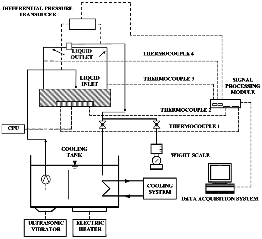
Figure 1. Schematic diagram of experimental apparatus.
of nanofluids consists of a 10−3 m3 storage tank, pump, and the flow rate measurement system. After the temperatures of the nanofluids are cooled to achieve the desired level, the nanofluids is pumped out of the storage tank, passed through the mini-rectangular fin heat sink, and returned to the storage tank. The flow rates are varied during a set of experiments with the help of a dimmerstat connected to the pump. The flow rates of the cooling nanofluids are controlled by adjusting the valve and measured by collecting the nanofluids with the precise cylinder for a period of time during 15 min and the nanofluids mass is measured by an electronic weight scale. The maximum variation of the mass flow rate of nanofluids as determined by such simple technique has been estimated to be ±3.5%. The nanofluids with suspending TiO2 nanoparticles in base fluids are used as working fluids. An average spherical particle size of TiO2 nanoparticles is about 21 nm. In the present study, the base fluids are the deionized water. The nanofluids are prepared by ultrasonic method with the constant nanoparticles concentration of 0.4% by volume without using surfactant. The heat sink is fabricated from the block of copper by the wire electrical discharge machine (WEDM) with the channel width of 1.00 mm. In order to minimize thermal resistance between the CPU-cooling block, cooling block-heat sink, a thin film of high thermal conductivity grease is applied at their junction interface. In Figure 1, the type T copperconstantan thermocouples with an accuracy of 0.1% of full scale are employed to measure the temperatures at various positions. The CPU temperature is measured by two type-T copper-constantan thermocouples. All thermocouples are pre-calibrated with dry box temperature calibrator.
2.2. Experimental Method
Nanofluids were used as coolant in the present experiments. The nanofluids were pumped into the mini-rectangular fin heat sink which installed on the CPU of PC in the normal direction with the base bottom as shown on Figure 2 and then returned to the storage tank. Experiments were conducted with various cooling nanofluids flow rates and operating condition of PC. The supplied load into the CPU was adjusted to achieve the desired level by setting the operating conditions of PC: no load and full load conditions. The energy consumption of the PC was measured by the watt-hour meter. The temperatures at each position and energy consumption were recorded in the period time of 200 minutes. Data collection was carried out using a data acquisition system (Data Taker).
3. Data Reduction
The heat transfer into the nanofluids is calculated from:
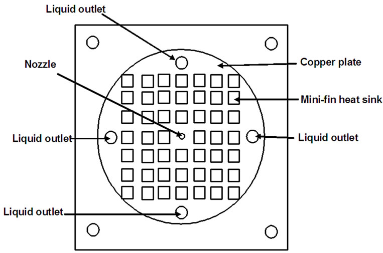
Figure 2. Schematic diagram of the inlet and outlet positions of the coolant.
 (1)
(1)
where  is the heat transfer by the nanofluids,
  is the mass flow rate of the nanofluids and
 ,
,  are the inlet and outlet temperatures of the nanofluids.
The heat transfer coefficient is calculated from the following equation:
 (2)
(2)
where h is the average heat transfer coefficient,  is the total heat transfer surface area of the heat sink and
  is the logarithm mean temperature difference which is given by:
 (3)
(3)
where  is the temperature of the heat sink.
The average base temperature of the heat sink can be calculated from:
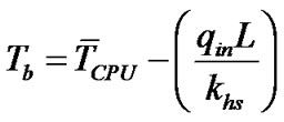 (4)
(4)
where  is the base temperature of the heat sink,
  is the CPU temperature,
  is the heat flux,
  is the base thickness of the heat sink and
  is the thermal conductivity of the heat sink.
The Nusselt number based on the nozzle diameter is calculated from the following equation:
 (5)
(5)
where  is the Nusselt number and
  is the diameter of the nozzle.
The thermal conductivity of the nanofluids is calculated from Yu and Choi [30] using the following equation:
 (6)
(6)
where  is the thermal conductivity of the nanofluids,
  is the thermal conductivity of the base fluid and
  is the thermal conductivity of the nanoparticles.
The density of the nanofluids is calculated from Pak and Cho [31] using the following equation:
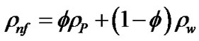 (7)
(7)
where  is the density of the nanofluids,
  is the density of the nanoparticles,
  is the density of the base fluid and
  is the volume fraction of the nanoparticles.
While the specific heat is calculated from Xuan and Roetzel [32] as follows:
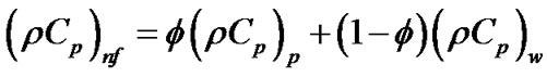 (8)
(8)
where  is the heat capacity of the nanofluids,
 is the heat capacity of the base fluid and
 is the heat capacity of the nanoparticles.
Analysis of the thermal resistance of the convective heat transfer of the nanofluids can be defined as
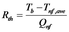 (9)
(9)
The uncertainties of measurements data and the relevant parameters obtained from the data reduction process are calculated. The maximum uncertainties of the relevant parameters in the data calculation are based on Coleman and Steel method [33]. The maximum uncertainties of relevant parameters are ±10% for heat transfer coefficient, ±10% for Nusselt number and ±5% for thermal resistance.
4. Results and Discussion
The supplied load into the CPU was adjusted by setting the operating condition of PC: full load and no load conditions. The relevant parameters are measured in the period time of 200 minutes. Figure 3 shows effect of coolant flow rate on the variation of CPU temperature for the jet nanofluids impingement cooling systems. The full load operating condition generates the heat higher than the no load operating condition. Therefore, the CPU temperatures from the full load condition are higher than those from the no load condition for the whole range of the period time. For the four different coolant flow rates, a larger CPU temperature drop is found for a larger coolant flow rate. The reason for this is because a larger coolant flow rate results in higher heat transfer rate and consequently lower CPU temperature.
Figure 4 shows the comparison between the CPU temperatures obtained from the jet nanofluids impingement technique, the jet liquid impingement and the conventional liquid cooling techniques. The thermal conductivity of nanofluids depends on the sizes and species of the nanoparticles, the concentration of nanoparticles in the base fluid and the combination of the nanoparticles and the base fluid properties. However, there are various correlations are proposed to predict the thermal conductivity and
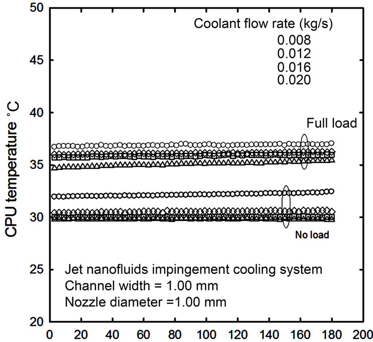
Figure 3. Effect of coolant flow rate on the CPU temperature for jet nanofluids impingement cooling system.
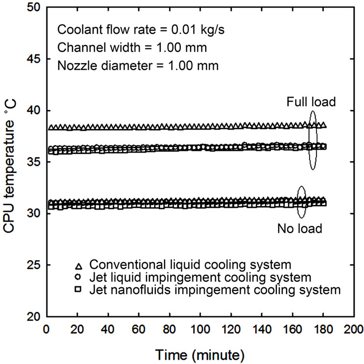
Figure 4. Comparison of CPU temperatures for different cooling techniques.
others properties of the nanofluids. Due to particle migration inside the heat sink, non-uniformity of the nanoparticles concentration has significant effect on the thermal conductivity and viscosity of the fluid. Therefore, in the present study, an average heat transfer characteristics are presented. At the same operating condition of CP, the CPU temperatures obtained from the jet nanofluids impingement cooling system are lower than those from the jet liquid impingement and from the conventional cooling systems, respectively. This is because the thermal conductivity of the nanofluids is higher than that of the base fluids therefore great potential for the enhancement of heat transfer.
Figure 5 shows the variation of the Nusselt number with nanofluids mass flow rate. As expected, the heat transfer rate is directly proportional to the nanofluids mass flow rate. In addition, Figure 5 also shows the comparison of the average Nusselt number obtained from the jet nanofluids impingement cooling technique, jet liquid impingement cooling technique, and conventional liquid cooling technique. It can be seen that the jet nanofluids impingement technique gives the Nusselt number higher than two other cooling techniques. The application of the nanofluids to the working fluid has significantly changed the fluid transport properties and flow characteristics. Therefore, the Nusselt number obtained from the jet nanofluids impingement are higher than those obtained from two other cooling techniques.
In this study, the overall heat sink performance can be shown in the thermal resistance form. The heat sink thermal resistance is defined as shown in Equation (9). Using this definition, thermal resistance of heat sink is a function of heat transfer coefficient. Due to higher heat transfer rate, the heat sink thermal resistance decreases with increasing flow rate. Based on results shown in Figure 6, it is seen that the thermal resistance obtained from the jet nanofluids impingement cooling technique are lower than those from the jet liquid impingement and from the conventional cooling techniques. This result can be realized from Equation (9) and nanofluids transport properties. Due to the increase in thermal conductivity, the contribution to the thermal resistance is mainly improved. In addition, the reduction of the thermal resistance is clearly due to the thermal dispersion.
5. Conclusions
Due to high level of heat generation, space limitation for set up the cooling system, and air cooling limitation, the jet nanofluids impingement cooling in the mini-rectangular fin channel heat sink for CPU of PC has been investigated. The jet nanofluids impingement cooling with mini-rectangular fin heat sink system is introduced as the

Figure 5. Variation of the Nusselt number versus mass flow rate for different cooling techniques.
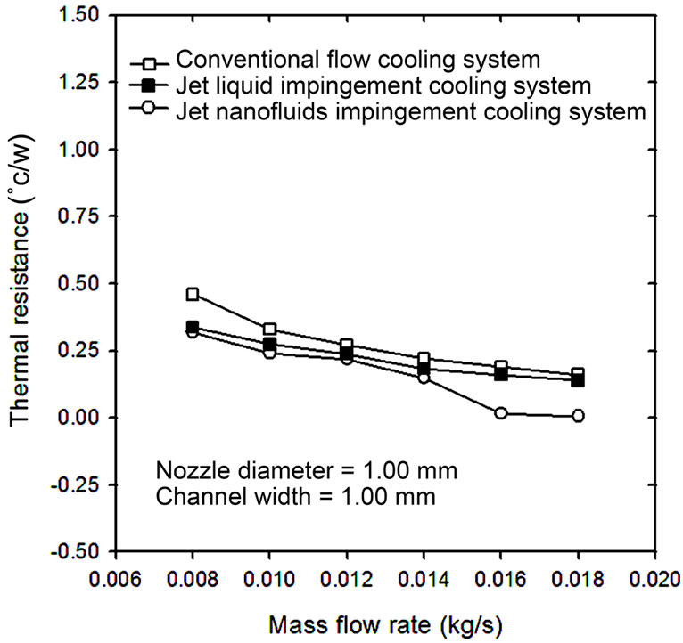
Figure 6. Comparison of thermal resistance versus mass flow rate for different cooling techniques.
couple active and passive heat transfer enhancement techniques. It is found that the CPU temperatures obtained from the jet nanofluids impingement cooling system are lower than those from the jet liquid impingement cooling system and the conventional liquid cooling system. However, this technique requires higher energy consumption. The results of this study are expected to lead to guidelines that will allow the design of the cooling system with improved thermal cooling performance for obtaining these devices in the specific temperature ranges.
6. Acknowledgements
The authors would like to express their appreciation to the Thailand Research Fund (TRF), the Srinakharinwirot University (SWU), and the King Mongkut’s University of Technology Thonburi (KMUTT) for providing financial support for this study.
7. References
[1] H. Y. Zhang, D. Pingala, T. N. Wong, K. C. Toh and Y. K. Joshi, “Single-Phase Liquid Cooled Micro Channel Heat Sink for Electronic Packages,” Applied Thermal Engineering, Vol. 25, No. 2, 2005, pp. 1472-1487. doi:10.1016/j.applthermaleng.2004.09.014
[2] X. Yu, “Development of a Plate-Pin Fin Heat Sink and Its Performance Comparisons with a Plate Fin Heat Sink,” Applied Thermal Engineering, Vol. 25, No.1, 2005, pp. 173-182. doi:10.1016/j.applthermaleng.2004.06.016
[3] Y. Peles, A. Kosor, C. Mishra, C. J. Kuo and B. Schneider, “Forced Convective Heat Transfer across a Pin Fin Micro Heat Sink,” International Journal of Heat and Mass Transfer, Vol. 48, No. 2, 2005, pp. 3615-3627. doi:10.1016/j.ijheatmasstransfer.2005.03.017
[4] A. Kosar and Y. Peles, “Convective Flow of Refrigerant (R123) across a Bank of Micro Pin,” International Journal of Heat and Mass Transfer, Vol. 50, No. 1, 2007, pp. 1018-1034.
[5] K. Yukut, “Experimental Investigation of Thermal Resistance of a Heat Sink with Hexagonal Fins,” Applied Thermal Engineering, Vol. 26, No. 2, 2006, pp. 2262- 2271. doi:10.1016/j.applthermaleng.2006.03.008
[6] M. M. Mohamed, “Air Cooling Characteristics of a Uniform Square Modules Array for Electronic Device Heat Sink,” Applied Thermal Engineering, Vol. 26, No. 2, 2006, pp. 486-493. doi:10.1016/j.applthermaleng.2005.07.013
[7] I. M. Didarul, “Study on Heat Transfer and Fluid Flow Characteristics with Short Rectangular Plate Fin of Different Pattern,” Experimental Thermal and Fluid Science, Vol. 31, No. 1, 2007, pp. 367-379. doi:10.1016/j.expthermflusci.2006.05.009
[8] R. Chein and J. Chuang, “Experimental Microchannel Heat Sink Performance Studies Using Nanofluids,” International Journal of Thermal Sciences, Vol. 46, No. 1, 2007, pp. 57-66. doi:10.1016/j.ijthermalsci.2006.03.009
[9] T. M. Jeng and S. C. Tzeng, “Pressure Drop and Heat Transfer of Square Pin-Fin Arrays in In-Line and Staggered Arrangements,” International Journal of Heat and Mass Transfer, Vol. 50, No. 1, 2007, pp. 2364-2375. doi:10.1016/j.ijheatmasstransfer.2006.10.028
[10] W. Duangtongsuk and S. Wongwises, “A Critical Review of Convective Heat Transfer of Nanofluids,” Renewable and Sustainable Energy Review, Vol. 11, No. 1, 2007, pp. 797-817. doi:10.1016/j.rser.2005.06.005
[11] V. Trisaksri and S, Wonwises, “Critical Review of Heat Transfer Characteristics of Nanofluids Review,” Renewable and Sustainable Energy Reviews, Vol. 11, No. 2, 2007, pp. 512-523. doi:10.1016/j.rser.2005.01.010
[12] L. Godson, B. Raja, D. M. Lal and S. Wongwises, “Enhancement of Heat Transfer Using Nanofluids—An Overview,” Renewable and Sustainable Energy Reviews, Vol. 14, No. 1, 2010, pp. 629-641. doi:10.1016/j.rser.2009.10.004
[13] C. J. Kobus and T. Oshio, “Development of a Theoretical Model for Predicting the Thermal Performance Characteristics of a Vertical Pin-Fin Array Heat Sink under Combined Forced and Natural Convection with Impinging Flow,” International Journal of Heat and Mass Transfer, Vol. 48, No. 3, 2005, pp. 1053-1063. doi:10.1016/j.ijheatmasstransfer.2004.09.042
[14] H. Y. Li, S. M. Chao and G. L. Tsai, “Thermal Performance Measurement of Heat Sinks with Confined Impinging Jet by Infrared Thermography,” International Journal of Heat and Mass Transfer, Vol. 48, Vol. 1, 2005, pp. 5386-5394.
[15] S. Geedipalli, A. K. Datta and V. Rakesh, “Heat Transfer in a Combination Microwave-Jet Impingement Oven,” Food and Bioproducts Processing, Vol. 86, No. 1, 2008, pp. 53-63. doi:10.1016/j.fbp.2007.10.016
[16] M. K. Sung and I. Mudawar, “Single-Phase and TwoPhase Heat Transfer Characteristics of Low Temperature Hybrid Micro-Channel/Micro-Jet Impingement Cooling Module,” International Journal of Heat and Mass Transfer, Vol. 51, No. 2, 2008, pp. 3882-3895. doi:10.1016/j.ijheatmasstransfer.2007.12.016
[17] M. K. Sung and I. Mudawar, “Single-Phase Hybrid Micro-Channel/Micro-Jet Impingement Cooling,” International Journal of Heat and Mass Transfer, Vol. 51, No. 1, 2008, pp. 4342-4352. doi:10.1016/j.ijheatmasstransfer.2008.02.023
[18] M. F. Koseoglu and S. Baskaya, “The Effect of Flow Field and Turbulence on Heat Transfer Characteristics of Confined Circular and Elliptic Impinging Jets,” International Journal of Thermal Sciences, Vol. 47, No. 2, 2008, pp. 1332-1346. doi:10.1016/j.ijthermalsci.2007.10.015
[19] V. Katti and S. V. Prabhu, “Heat Transfer Enhancement on a Flat Surface with Axisymmetric Detached Ribs by Normal Impingement of Circular Air Jet,” International Journal of Heat and Fluid Flow, Vol. 29, No. 1, 2008, pp. 1279-1294. doi:10.1016/j.ijheatfluidflow.2008.05.003
[20] P. R. Kanna and M. K. Das, “Heat Transfer Study of Two-Dimensional Laminar Incompressible Offset Jet Flows,” International Journal of Thermal Sciences, Vol. 47, No. 1, 2008, pp. 1620-1629. doi:10.1016/j.ijthermalsci.2008.01.003
[21] F. Cirillo and G. M. Isopi, “Glass Tempering Heat Transfer Coefficient Evaluation and Air Jets Parameter Optimization,” Applied Thermal Engineering, Vol. 29, No. 2, 2009, pp. 1173-1179. doi:10.1016/j.applthermaleng.2008.06.005
[22] M. Goodro, J. Park, P. Ligrani, M. Fox and H. K. Moon, “Effects of Hole Spacing on Spatially-Resolved Jet Array Impingement Heat Transfer,” International Journal of Heat and Mass Transfer, Vol. 51, No. 1, 2008, pp. 6243- 6253. doi:10.1016/j.ijheatmasstransfer.2008.05.004
[23] T. M. Jeng, S. C. Tzeng and H. R. Liao, “Flow Visualizations and Heat Transfer Measurements for a Rotating Pin-Fin Heat Sink with a Circular Impinging Jet,” International Journal of Heat and Mass Transfer, Vol. 52, No. 2, 2009, pp. 2119-2131. doi:10.1016/j.ijheatmasstransfer.2008.10.028
[24] B. N. Hewakandamby, “A Numerical Study of Heat Transfer Performance of Oscillatory Impinging Jets,” International Journal of Heat and Mass Transfer, Vol. 52, No. 2, 2009, pp. 396-406.
[25] C. T. Nguyen, N. Galanis, G. Polidori, S. Fohanno, C. V. Popa and A. L. Bechec, “An Experimental Study of a Confined and Submerged Impinging Jet Heat Transfer Using Al2O3-Water Nanofluids,” International Journal of Thermal Sciences, Vol. 48, No. 3, 2009, pp. 401-411. doi:10.1016/j.ijthermalsci.2008.10.007
[26] M. F. Koseoglu and S. Baskaya, “Experimental and Numerical Investigation of Natural Convection Effects on Confined Impinging Jet Heat Transfer,” International Journal of Heat and Mass Transfer, Vol. 52, No. 1, 2009, pp. 1326-1336. doi:10.1016/j.ijheatmasstransfer.2008.07.051
[27] S. W. Chang, T. L. Yang and D. W. Shih, “Jet-Array Impingement Heat Transfer in a Concentric Annular Channel with Rotating Inner Cylinder,” International Journal of Heat and Mass Transfer, Vol. 52, No. 1, 2009, pp. 1254-1267. doi:10.1016/j.ijheatmasstransfer.2008.08.023
[28] M. A. R. Sharif and A. Banerjee, “Numerical Analysis of Heat Transfer Due to Confined Slot-Jet Impingement on a Moving Plate,” Applied Thermal Engineering, Vol. 29, No. 1, 2009, pp. 532-540. doi:10.1016/j.applthermaleng.2008.03.011
[29] B. P. Whelan and A. J. Robinson, “Nozzle Geometry Effects in Liquid Jet Array Impingement,” Applied Thermal Engineering, Vol. 29, No. 1, 2009, pp. 2211- 2221. doi:10.1016/j.applthermaleng.2008.11.003
[30] W. Yu and S. U. S. Choi, “The Role of Interfacial Layers in the Enhanced Thermal Conductivity of Nanofluids: A Renovated Maxvell Model,” Journal of Nanoparticle Research, Vol. 5, No. 1, 2003, pp. 167-171. doi:10.1023/A:1024438603801
[31] B. C. Pak and Y. I. Cho, “Hydrodynamic and Heat Transfer Study of Dispersed Fluids with Submicron Metallic Oxide Particles,” Experimental Heat Transfer, Vol. 11, No. 2, 1998, pp. 151-170. doi:10.1080/08916159808946559
[32] Y. Xuan and W. Roetzel, “Conceptions of Heat Transfer Correlation of Nanofluids,” International Journal of Heat and Mass Transfer, Vol. 43, No. 19, 2000, pp. 3701- 3707. doi:10.1016/S0017-9310(99)00369-5
[33] H. W. Coleman and W. G. Steele, “Experimental and Uncertainty Analysis for Engineers,” John Wiley & Sons, New York, 1989.
Nomenclatures
 : total heat transfer surface area of the heat sink, m2.
 : nozzle diameter, m.
 : average heat transfer coefficient, W/(m2 K).
 : thermal conductivity of the nanofluids, W/(m K).
 : Nusselt number.
 : heat flux, W/m2.
 : thermal resistance, K/W.
 : the base temperature of the heat sink, ˚C.
 : CPU temperature, ˚C.
 : logarithm mean temperature difference, ˚C.
Greek Symbols
 : density of the nanofluids.
 : heat capacity of the nanofluids.
 : heat capacity of the nanoparticles.
 : viscosity of the nanofluids.