Open Journal of Safety Science and Technology
Vol.06 No.03(2016), Article ID:72215,6 pages
10.4236/ojsst.2016.63006
Design of Monitoring System on QDQ2-1 Type Water Electrolysis Hydrogen Equipment
Tao Jiang, Ping Yu, Yu Liu, Jiajia Zhang, Shuyong Zhen*
Hebei Province Meteorological Technical Equipment Center, Shijiazhuang, China
![]()
Copyright © 2016 by authors and Scientific Research Publishing Inc.
This work is licensed under the Creative Commons Attribution International License (CC BY 4.0).
http://creativecommons.org/licenses/by/4.0/


Received: August 14, 2016; Accepted: September 27, 2016; Published: September 30, 2016
ABSTRACT
In order to solve the deficiencies of the prior detection method on QDQ2-1 type water electrolysis hydrogen equipment, the key state parameters of hydrogen plant, such as hydrogen storage pressure, the operating voltage and the temperature of the tank, can be monitored in remote online by making full use of modern communications technology and data collection [1] . Once the hydrogen plant is abnormal, the alarm can be issued in time. The multi-point real-time automatic monitoring [2] mode can be realized in the hydrogen production process. The safe operation of hydrogen production work can be greatly improved by the advanced monitoring mode.
Keywords:
Water Electrolysis Hydrogen, Online Monitoring, Safe Operation, Multi-Point Real-Time Automatic Monitoring Mode

1. Introduction
Hydrogen Safety is one of the main production safeties in the meteorological department, when the sounding stations QDQ2-1 type water electrolysis hydrogen production equipment work, the status parameters are mounted on the dashboard instrument mechanical or digital display through the hydrogen chamber. Equipment operating conditions can only be understood through tour dashboard. Since the safe operation of equipment depends entirely on the judge observed hydrogen production staff on duty, any omissions are likely to cause major accidents.
Due to lack of water electrolysis hydrogen existing remote equipment monitoring technology, it should make full use of the single-chip computer and modern communications technology [3] to achieve the hydrogen plant operating state information of remote monitoring. When the system is abnormal, the system automatically starts the live sound and light alarms and alarm data center, which will improve the safety of hydrogen production work.
2. System Design
QDQ2-1 type water electrolysis hydrogen plant monitoring system design is divided into three parts: First, water electrolysis hydrogen equipment remote monitoring terminal which is an important part of water electrolysis hydrogen equipment. It is mainly used for hydrogen production station of the monitoring parameters of data acquisition, analysis, display, fault alarm and communication. Second, the data transmission section which includes outherner and communications network. Third, the data center which is responsible for receiving, storage, analysis and alarm data. System framework shown in Figure 1.
2.1. Hardware Design
The producing hydrogen pressure, voltage, tank temperature, current, three-phase voltage, pressure hydrogen storage, hydrogen concentration in the hydrogen storage chamber hydrogen leak, the hydrogen purity of the state parameter can be collected by the monitor terminal which can complete data storage and display. At the same time, the data can be transmitted to the data center and comparative analysis. If the state is abnormal, the alarm can be issued immediately. The structure shown in Figure 2.
Acquisition and control unit is one of the core components of the monitoring terminal which is made up of industrial-grade high-speed components. The display control unit bears the working state parameters of display, storage, and data centers with a number of important tasks Ethernet communication [4] in part by power supply batteries, switching power supplies and charge controllers, the role of the charge controller is charging, power supply and protection circuit. Communication using GPRS and Ether- net [5] are two ways to improve communication reliability.
Acquisition control unit is one of the core components of the monitoring terminal. Using industrial grade high-speed components, High sampling precision, fast conversion speed, can collect the analog switch, and switching output function. Bear the important task of signal acquisition, alarm output and communication with the remote data center. A display control unit undertakes the work state parameter display, storage and data center Ethernet communication and other important tasks. The power supply
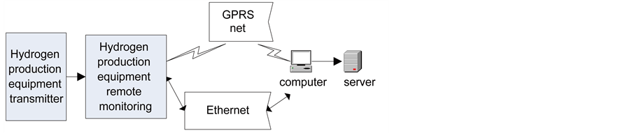
Figure 1. The framework of QDQ2-1 water electrolysis hydrogen production equipment monitoring system.

Figure 2. The structure of water electrolysis hydrogen production equipment remote monitoring terminal.
is composed of a battery, a switch power supply and a charging controller, and the charging controller is a charging, power supply and protection circuit. Communication use GPRS and Ethernet two ways to improve communication reliability. The monitoring terminal adopts fully sealed chassis, can effectively prevent dust and moisture. The inside of the box parts are various connectors, anti salt, anti moisture and anti fungal treatment. The transmitter installations in hazardous area equipment are explosion-proof equipment, installation of explosion-proof requirements in accordance with the relevant national standard construction.
2.2. Software Design
2.2.1. The Calculation of the True Value of the Transmitter
The transmitter conversions range each acquisition parameters as the standard range of 4 mA - 20 mA. According to the type of QDQ2-1 water electrolysis hydrogen production system, the range of the transmitter is selected. A time value acquisition transmitter output, the formula (1) can be calculated to represent the true value, and the relationship is as follows:

 ―The maximum range of the transmitter;
 ―For a time the value of the transmitter output;
Y―The true value of the acquisition.
For example: Pressure transmitter, range 1.0 MPa, when it is output 4 mA, the corresponding pressure should be 0 MPa, 20 mA corresponding to the pressure of 1.0 MPa, 12 mA corresponding to the pressure of 0.5 MPa.
2.2.2. Acquisition Control Software
The working flow chart of the collection and control software is shown in Figure 3. The program starts running after the first initialization of the port, the operating parameters of AD etc. Start the AD conversion, the analog signal of each transmitter for digital, using the calculated value calculation formula of ultimate measurement values [6] ; the measured value is compared with the stored value of the alarm threshold, to decide whether to achieve fault alarm conditions. At the same time, the real-time receiving software of the collector switch signal from alarm input, judging the state of alarm. In case of alarm, the program will immediately alarm control in sensor output. At the same time, the data acquisition software and the data center software and display control unit for communication, the measurement results, alarm information sent out, and receive feedback information. Analog acquisition is carried out in the single chip microcomputer AD interrupt. Each AD data is after 60 times of sampling, the sampling value is accumulated after the average, as a AD sample data, the data sent to the industrial computer for storage.
2.2.3. Data Receiving Software
The software is mainly responsible for receiving data acquisition control and data receiving function. The software first initializes the basic information of the each hydrogen monitoring terminal station, buffer, communication network parameters, the establishment of multi thread. After initialization, each sending commands to the monitoring

Figure 3. Collector software workflow.
terminal hydrogen production data according to the preset sampling interval, and then waits to receive data. Receive the returned data monitoring terminal hydrogen, stored in a data buffer [7] , then the thread data will be stored in the database, the latest state information and update the site. The flow chart is shown in Figure 4.
2.3. Networking Design
Hydrogen production monitoring terminal and data center through the network to communicate, if the system communication failure, the monitoring parameter of hydrogen production site and alarm information cannot be promptly sent. In order to ensure the smooth communication system, According to the actual working environment, two communication modes of GPRS and Ethernet are designed. The two communication modes simultaneously, thus improving the stability and reliability of the whole system. GPRS communication is carrying business data based on GSM network, after years of construction, its coverage continues to expand, has become the mature communication network, and has good coverage and stability. Hebei meteorological service system uses a special form of APN local area network [8] with high security. GPRS use without geographical restrictions, as long as the signal can cover the local communication is free, But the transmission reliability than Ethernet, stability is affected by the presence of short time communication interruption, resulting in data cannot be sent.
Today is the existing Ethernet LAN universal communication protocol standards; network has advantages of steady, fast communication. Using meteorological system internal LAN, realize the Provincial Meteorological Bureau Meteorological Bureau and

Figure 4. Data center receiving software workflow.
the county to Ethernet interconnection. ALAN network interface in the field of hydrogen production equipment, to meet the conditions of Ethernet connection.
3. Conclusion
At present in China Meteorological system meteorological sounding station, Hydrogen production is not only related to the high altitude meteorological service whether normal development, it is a matter of life and death. According to the characteristics of meteorological work of the hydrogen production system, based on the principle of water electrolysis hydrogen, based on the technology of single chip microcomputer [9] , industrial computer and computer, water electrolysis equipment monitoring system by Ethernet and GPRS, a real time monitoring and multi point alarm model for hydrogen production safety is established. Changed in the past, a single manual inspection work mode improves the safety of hydrogen production work.
Cite this paper
Jiang, T., Yu, P., Liu, Y., Zhang, J.J. and Zhen, S.Y. (2016) Design of Monitoring System on QDQ2-1 Type Water Electrolysis Hydrogen Equipment. Open Journal of Safety Science and Technology, 6, 70-75. http://dx.doi.org/10.4236/ojsst.2016.63006
References
- 1. Zeng, K. and Zhang, D. (2010) Recent Progress in Alkaline Water Electrolysis for Hydrogen Production and Applications. Progress in Energy and Combustion Science, 36, 307-326.
http://dx.doi.org/10.1016/j.pecs.2009.11.002 - 2. Renaud, G., Lazzari, R., Revenant, C., et al. (2003) Real-Time Monitoring of Growing Nanoparticles. Science, 300, 1416-1419.
http://dx.doi.org/10.1126/science.1082146 - 3. Poisel, R. (2011) Modern Communications Jamming: Principles and Techniques. Artech House.
- 4. Imanaka, T. and Otsuka, Y. (2001) Ethernet Communication Redundancy Method. US Patent 6282669.
- 5. Cortés, F., Gallardo, S., Barrero, F., et al. Controller Area Network Domotic Prototype Using GPRS and Ethernet Interfaces for Virtual Monitoring Applications. Lusas de Electrical Ingeniería, 9.
- 6. Muramatsu, Y., Fukushima, N., Nitta, Y., et al. (2006) Method and Apparatus for AD Conversion, Semiconductor Device for Detecting Distribution of Physical Quantity, and Electronic Apparatus. US Patent 7129883.
- 7. Janoska, M.W., Heller, A.D. and Pezeshki-Esfahani, H. (2003) Method and Apparatus for Data Buffer Management in a Communications Switch. US Patent 6539024.
- 8. Horn, G.B., Meylan, A. and Kapoor, R. (2013) System and Method of Offloading Traffic to a Wireless Local Area Network. US Patent Application 13/830355.
- 9. Wu, H., Tang, M. and Huang, G. (2010) Design of Multi-Functional Street Light Control System Based on AT89S52 Single-Chip Microcomputer. 2010 2nd International Conference on Industrial Mechatronics and Automation (ICIMA), 134-137.