Open Journal of Safety Science and Technology
Vol.04 No.04(2014), Article ID:51539,11 pages
10.4236/ojsst.2014.44018
A Novel Application of Inertial Measurement Units (IMUs) as Vehicular Technologies for Drowsy Driving Detection via Steering Wheel Movement
Samuel A. Lawoyin, Ding-Yu Fei, Ou Bai
Department of Biomedical Engineering, Virginia Commonwealth University, Richmond, VA, USA
Email: lawoyins@vcu.edu, fei@vcu.edu,obai@vcu.edu
Copyright © 2014 by authors and Scientific Research Publishing Inc.
This work is licensed under the Creative Commons Attribution International License (CC BY).
http://creativecommons.org/licenses/by/4.0/


Received 6 September 2014; revised 4 October 2014; accepted 6 November 2014
ABSTRACT
Introduction: Vehicular technologies intended for the improvement of driver safety are especially critical today in the view of the thousands of deaths that occur annually due to drowsy driving. Current technologies include physiological methods like electroencephalography (EEG), behavioral methods including driver video monitoring, and vehicle measures which include lane and steering wheel tracking. These current technologies are impractical in their current implementations as they cannot readily be used outside of laboratory settings due to their requirements for intrusive electrodes, expensive cameras, and complex equipment. An earlier article demonstrated an effective method for wheel tracking using only an accelerometer; however the introduction of integrated gyroscopes and accelerometers has afforded further opportunities. Objective: This paper introduces a novel, low-cost, and easy to implement an approach to address this unmet problem. Method: Through the use of an Inertial Measurement Unit (IMU) combining a gyroscope and an accelerometer, measurements of steering wheel behavior were recorded in both simulator and real world driving while compared against a standard potentiometer. Results: The excellent agreement between potentiometer recorded angles and IMU estimated angles (R2 = 0.98, P < 0.001) suggests that the complicated installation of potentiometers in vehicle steering columns is no longer a necessary step for steering wheel monitoring. Conclusion: This paper presents an IMU based method for drowsy steering-wheel behavioral tracking which is cost-effective, easy to implement, and accurately estimates steering behaviors. The results suggest that this novel vehicle technology offers hope for improving road safety.
Keywords:
Driver Safety, Drowsy and Fatigued Driving, Accidents, Accident Prevention, Inertial Measurement Units

1. Introduction
Many methods have been proposed for the detection of drowsy or fatigued driving. Researchers have tried physiological measures which include heart rate, breathing rate, and brain activity via electroencephalography (EEG). Behavioral measures including eye blinks and eye closures have also been used. Because these measures have obtrusive properties, they are impractical for daily use with commuters and researchers have turned to vehicle-based measures instead. Vehicle-based measures are embedded into the vehicle and its systems, making them unobtrusive to the driver. These measures include monitoring of the drivers steering patterns for signs of declining alertness and lapses in wakefulness which contribute to road accidents.
Drowsy and fatigued driving is a significant problem. It is responsible for about 1200 deaths and 76,000 injuries every year in the United States alone [1] and the annual numbers worldwide are even higher. Greater than 14% of respondents who polled in Ontario Canada admitted having fallen asleep or nodded off while driving [2] . Sleep-deprived individuals become undetected drowsy drivers on the roads and highways [3] . The other types of drowsy drivers are those who initially received sufficient sleep but engaged in prolonged driving which caused their awareness to deteriorate over time [4] . Prolonged wakefulness is just as dangerous to driver safety as alcohol intoxication [5] .
Physiological measures of drowsiness including EEG are not a practical measure of drowsiness due to the complexity of setup and the non-portability of equipment. Commuters would be unable or unwilling to prepare and apply EEG to themselves daily. In addition research has shown that engine vibrations affect EEG outcomes [6] .
Eyelid closures are behaviors that can be observed for drowsiness detection. Eye closures which last for more than half a second are especially indicative of sleepiness [7] . PERcentage of eye CLOSure (PERCLOS) refers to the percent of time that a driver’s eyelids are closed over a given interval. It has shown good promise as a means for drowsiness detection [8] . Video-based eye closure monitoring methods are ineffective if the driver is wearing eyeglasses [9] and give false positive readings if the driver looks down and around him [10] . Electrooculography (EOG) methods for PERCLOS are too intrusive for widespread daily use due to their use of electrodes and wires.
An important vehicle-based method for determining drowsy driving is the monitoring of a driver’s Steering Wheel Movements (SWM) for drowsy patterns. The relationship between SWM and driver drowsiness has been well documented. The correlation between a driver’s intervals of steering adjustments and their level of drowsiness has been consistently seen by researchers [11] [12] . Drivers make fewer regular maneuvers when drowsy than when alert. Despite the decline in overall steering inputs, the fewer inputs made are sudden and larger in degree [13] [14] . Steering inputs in fatigued drivers are shown to have fewer micro corrections and more macro- corrections, with sleeping drivers making no corrections [13] -[15] . It has been demonstrated that as the majority of sampled drivers become drowsy, they tend to increasingly trend towards faster and larger steering corrections [13] .
With the knowledge that SWM is a highly effective and highly accurate measure of drowsy driving, there have been several methods used by researchers to monitor SWM. Sayed and Eskandarian [16] measured SWM using built-in equipment found in complex vehicle simulators. This approach is cost-prohibitive to the average user and excessively powered for users requiring only SWM monitoring without extra options. Thiffault and Bergeron [13] placed potentiometers along the axis of the steering column to directly measure the turn angle. This would require users to have the technical knowledge and dexterity to install a potentiometer into the steering column of their vehicle or vehicle simulator. Potentiometer use would also require the dismantling of the current vehicle setup to install the potentiometer. Despite the numerous progresses made by researchers towards an effective method of deploying the SWM method on a wide scale, the use of a gyroscope has not been explored despite its ubiquitous use as the standard for rotational measurements in ships, airplanes, submarines and space-crafts. Despite the large amounts of linear vibrations, noise, jolts and accelerations in the gyroscopes routine applications, it remains a highly accurate and widely proliferated standard of rotation measurement. Even though gyroscopes are highly proliferated measures of rotation, their positional measurements have a tendency to drift with time [17] . Luinge [17] used gyroscopes to measure human orientation. To address the drift problem, a 3D accelerometer which served as a tilt sensor was used to continuously recalibrate the gyroscope. Lee et al. [18] used a gyroscope to estimate the posture of a mobile inverted pendulum. For drift correction in that case, a tilt sensor was fused with the gyroscope. In spaceflight, NASA uses accelerometers to detect and null errors generated in IMU devices. The accelerations caused by the earth are definitely known, and any discrepancies are considered errors. In terrestrial flights, vacuum gyroscope drifts cause errors in directional readings and pilots have to manually recalibrate the readings by hand, referencing a compass. Ring Laser Gyroscopes (RLGs) are less prone to drift, but they cost upwards of $300,000 for a tri-axial unit [19] . Greene [19] proposed the use of a piezoelectric gyroscope in place of an RLG. Due to drift, an accelerometer was used to stabilize the gyroscopes. In our case, the use of regular automatic recalibration from an accelerometer would ensure seamless operation.
In this study, an Inertial Measurement Unit (IMU) based approach for monitoring the SWM is proposed. IMU devices include gyroscopes and accelerometers. Due to modern Micro Electro Mechanical (MEMS) technologies, gyroscopes and accelerometers are now very affordable to obtain and have very compact form factors. They are no longer restricted by cost or complexity to advanced navigation devices. The proposed use of gyroscopes for SWM monitoring requires a minimal setup that is easy to install and uninstall. The only requirement is that the gyroscope should be affixed to a surface of the steering wheel that would allow the device to be perpendicular to the steering column axis.
An earlier study conducted showed the high accuracy and efficacy of using an accelerometer for the monitoring of drowsiness via SWM methods [20] . The method proposed in this study depends upon the accurate accelerometer-based method from the earlier study for solving the gyroscopes drift problems. In low noise or simulator based environments, the accelerometer-based method might be adequate or preferable if an experimenter has access to cheaper accelerometers. Although there has come to be widespread use of analog accelerometers, there has since come about the availability of 6-axis digital MEMS sensors which incorporate a gyroscope and an accelerometer in a tiny footprint (4 × 4 × 0.9 mm) such as the one used in this study. The benefit of this newer sensor type is that the combined setup helps to simultaneously improve the accuracy of both the accelerometer and the gyroscope. Because accelerometers are prone to linear vibration noise and gyroscopes are prone to slow drifts, the combination of the two sensors has provided new opportunities for SWM monitoring that were originally not available in discrete analog accelerometers. Further, these opportunities are in a very tiny, unobtrusive, and inexpensive package.
An algorithm was developed in this study for monitoring SWM that utilizes a gyroscope’s proficiency in detecting angular velocities. The gyroscope outputs the rate of angular change, and then the proposed algorithm interprets this data into SWM position angles with the assistance of an integrated accelerometer which accounts for drift and is located on the same single-DIEmems.
This solution can meet the unmet problem to curb drowsy driving. Despite the safety efforts of the NHSTA and The Federal Highway Administration (FHWA), drowsy drivers continue to take to the wheel and deaths and injuries continue to yield consistently high annual fatality figures. The knowledge for detecting drowsy driving exists but remains within the positive results of numerous successful driving trials. Manufacturers have found no adequate method to deploy these known techniques. The necessity for a practical and inexpensive means for drowsy driving monitoring is especially pertinent as an effective counter to the high fatality numbers. The proposed method is simple, cost-effective and provides not only for drowsy monitoring on new vehicles, but also allows for retrofitting on older vehicles and current model vehicles which on average continue to be manufactured with no drowsy driving detection mechanisms.
Section 2 describes the method and materials for using a gyroscope-accelerometer fusion for SWM detection, Section 3 describes the various tests performed to evaluate the efficacy of the method, Section 4 lists the results obtained from the design and testing of the method, while Sections 5 and 6 discuss the results and list conclusions.
2. Material and Method
2.1. The Basic Concept and Algorithm to Calculate SWM Using a Gyroscope-Accelerometer Fusion
Gyroscopes detect angular velocity and they can be used to derive information about the angular orientation of the steering wheel. An equation for real time monitoring of the rotational position of a gyroscope is given by [21] :
 (1)
(1)
where the gyroscope positional angle
 is based upon knowledge of the last positional sample
 as well as knowledge of the angular displacement since the last sample, which is the product of the
rate of angular change , and the sample interval,
 . The new position of gyroscope orientation can be
determined as
 with the above Equation (1). The equation was designed especially for capturing rota
tional movements originating from human motion [21] . SWM is a product of human motion, and will be served well by this method.
A drawback to using gyroscopes for detection of angular rotation is the tendency for gyroscope positional values to drift [17] [21] .
The second part of the proposed IMU device is the accelerometer. An equation for extracting SWM angle solely via an accelerometer is given as [20] :
 (2)
(2)
where
 was the SWM angle being estimated from the accelerometer readings of
 and
and ,
,
 had a strong positive correlation with the steering wheels SWM angle
 [20] .
The addition of an accelerometer to the gyroscope compensated for gyroscope drift via the accelerometers perpetual ability for gravitational alignment. This is predicated upon the fact that the operation of Equation (2) depends upon relative readings of gravity on the accelerometers separate axes. The accelerometers tendency to pick up linear vibrations was in turn countered by the gyroscope which has sensitivity to angular velocity. The IMU fusion led to a highly effective combination. When the steering wheel was in a neutral position as shown in Figure 1, the main sensor was fastened to the steering wheel surface such the accelerometer gave a neutral angular reading of
 and the gyroscope Z-axis (
 marked as “
 ” was parallel to the steering column axis.
Combining Equations (1) and (2), a complimentary filter was designed to maximize the strengths of both IMU devices. An ideal relationship between
 and
and
 which would be easy to update in real time was found to be the causal system:
 (3)
(3)

Figure 1. The mapping of the IMU device to the steering wheel.
which is effectively a weighted addition of Equation (1) and Equation (2) with a few slight modifications. The
first modification was that
 took over the role of
 . This consequentially resulted in the causal system referencing
 rather than
 , which is incidentally more correct for the newly formed
system in terms of accurately calculating angle based in part upon the last known position. The second difference was that the angular velocity output of the gyroscope was averaged over current and last known reading. This was intended to provide a smoother reading and to improve overall accuracy rates of the newly fused system. At 250 Hz of sampling frequency, which yields 250 samples each second, the averaging of only 2 samples will not adversely affect the overall signal even in the very short term.
Finally, βgyro and βaccel were chosen as the coefficients for determining the percentage contribution of each element in Equation (3) to the overall IMU fusion reading of SWM. The summation case therefore must always hold that:
 (4)
(4)
The full process for determination of the coefficient weights for Equation (3) is described in Section 3.
For comparison against current potentiometer based SWM angle recordings, a linear potentiometer in series with the steering axis was used as a reference. Linear potentiometer output voltages vary in linear proportion to their angle of rotation and can be modelled as a standard linear equation:
 (5)
(5)
where
 was the steering wheel angle of rotation in degrees (˚) and
 was the potentiometer voltage in volts (V).
 was the slope of the linear relationship and
 was the y-intercept of the linear relationship.
To customize our model, the parameters
 and
and
 were generated by sampling 90 data points per quadrant of the steering wheel, yielding approximately 1 sample of
 per 1˚. Using these data points to generate a linear relationship gave values of
 and
and . All further potentiometer readings of SWM angle were calculated by using these parameters with Equation (5) for derivation of
 .
.
2.2. Equipment
The steering wheel used for simulator tasks was the Top Drive GT (Logic3, Hertfordshire, England). Simulator driving tasks were performed using the OpenDS driving simulation software.
An MPU-6050 (InvenSense, San Jose, California) which is a 6-axis combined MEMS gyroscope + accelerometer was the main sensor. The sensitivity of the gyroscope was set at ±250˚∙s−1 while the sensitivity of the accelerometer was set at ±2 g. At 4 mm ´ 4 mm × 0.9 mm and weighing less than a gram, the sensor lends itself to portability and non-intrusiveness in any SWM application
The IMU data was collected using an amplifier based on the TI-ADS1299 Analog Front-End (Texas Instruments, Dallas, TX). All data were sampled at 250 Hz.
Data were analyzed with MATLAB. For statistical analysis, linear correlations between data were determined through linear regression, Pearson’s Linear Correlation coefficients, and Spearman’s Rho. P-values were recorded at α = 0.05 unless otherwise specified. The correlations between potentiometer measured SWM and SWM estimated via the gyroscope-accelerometer algorithm were determined using the cross correlation (xcorr) function of the MATLAB signal processing toolbox.
3. Testing
3.1. Test for Applicability of SWM Monitoring with an Accelerometer as the Sole IMU Input
For this test, Equation (3) was used for generating the SWM signal . However, the signal here was generated using IMU data collected from the accelerometer only during road tests. For this purpose, βgyro was set to 0. The resulting signal was compared against potentiometer readings during the same period to determine the usability of the signal and its correctness.
3.2. Test for Applicability of SWM Monitoring with a Gyroscope as the Sole IMU
Similar to the previous test, Equation (3) was used for generating the SWM signal
 using IMU data collected from the gyroscope during road tests. In this case, βaccel was set to 0. The resulting signal was compared against potentiometer readings during the same period to determine the usability of the signal and its correctness.
3.3 Test for Equal Weighting of Gyroscope: Accelerometer Coefficients βgyro:βaccel
This test was intended to implement true signal combinations as described by Equation (3). Accelerometer and gyroscope input were initially combined at a ratio of 50:50 for βgyro:βaccel.
3.4. Test to Determine Optimal Weights for Gyroscope: Accelerometer Coefficients βgyro:βaccel
Combining the two inertial measures of SWM measurements into a single efficient unit required the optimal weight distribution of each component. It was intended that the shock resistant gyroscope which was sensitive to angular rotations inherent to steering behavior and less sensitive to linear or translational noise would provide the bulk of SWM monitoring data. It was also intended that the drift resistant accelerometer would contribute just enough orientation data to ensure that the gyroscope measurement was perpetually calibrated against gravity so that the angle did not drift with time.
Road tests on the high way were useful for making a determination of what ratio of βgyro:βaccel was most effective. The aim was to decide which weight ratio yielded the best data in relation to the potentiometer, since the method was to eventually be an efficient replacement of the potentiometer for steering behavior monitoring.
3.5. Test for Accuracy of SWM Readings against Linear Potentiometer Using Selected Weights
After the setup from 2.2 had been used to establish a relationship between ,
,
 , and
, and , as well as a standard for
 , a participant was recruited to perform driving simulator activities for 45 minutes. The correla- tion between
 and
and
 over this prolonged period was calculated.
Once strong correlation was seen in a simulator environment, an actual road test was performed which involved the physical mounting of the simulator’s steering wheel platform into the vehicle interior while driving tasks were performed by a passenger. This test involved about 20 minutes of driving tasks involving high speed highway driving and city driving in stop-and-go traffic.
4. Results
Data were analyzed using MATLAB. Correlations between the inertial unit’s SWM data and the potentiometers SWM data were determined via Pearson’s Linear Correlation coefficients, Spearman’s Rho, and Kendall’s tau. Signal cross correlation between the Inertial Measurement Units output signal and the potentiometers output signal were determined through the xcorr function of the MATLAB signal processing toolbox. P-values were recorded at α < 0.05.
4.1. SWM Monitoring with an Accelerometer as the Sole IMU
For this test, Equation (3) was used to generate the SWM signal
 from IMU data collected from the accelerometer during road tests. In this case, βgyro was set to 0.
The purely accelerometer signal demonstrated noticeable amounts of road noise during road tests (Figure 2(a)). Although a low pass filter conveniently removed the noise (Figure 2(b)), the use of gyroscope fusion demonstrated better results when optimal weighting eliminated the need for hardware or software filtering (Section 4.4). Table 1 shows the results obtained when each IMU device was used as the sole SWM input. Table 1 also shows the result of a 50:50 IMU device input ratio.
4.2. SWM Monitoring Using a Gyroscope as the Sole IMU Input
The SWM signal
 was generated from IMU data collected solely from the gyroscope during road tests. In this case, βaccel was set to 0. Figure 2(c) shows a 24 second section of the gyroscope output waveform after about 10 minutes of road driving. While the gyroscope output was of the correct waveform to match the poten- tiometer output, the drifting caused the signal to eventually center around 150˚ (Figure 2(c)) whereas it would
 (a) (b)
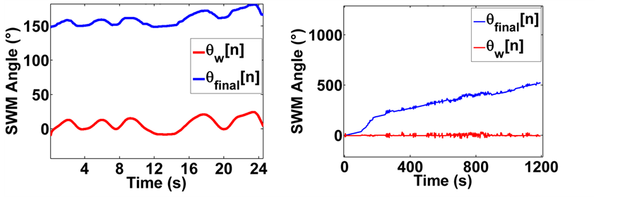 (c) (d)
 (e)
(e)
Figure 2. (a) Accelerometer only SWM signal; (b) Accelerometer only SWM signal passed through a 4th order low pass Butterworth filter; (c) Gyroscope only signal demonstrating slow drift; (d) Gyroscope only signal from road test demonstrating how the gyroscope signal would wander into a slow drift in the longer term; (e) A 50:50 distribution of accelerometer: gyroscope signals.

Table 1. Various IMU device ratios and their correlation to potentiometer.
always be centered at 0˚ when calibrated by the accelerometer complement.
4.3. SWM Monitoring Using Equal Weighting of Gyroscope and Accelerometer Inputs
This test was intended to implement true signal combinations as described by Equation (3). Accelerometer and gyroscope input were initially combined at a ratio of 50:50 for βgyro:βaccel. The signal generated from this ratio yielded a fairly noisy signal (Figure 2(d)). However, the signal generated through this weighting was less noisy than the signal generated by the accelerometer only.
4.4. Optimal Weights Discovery for Gyroscope: Accelerometer Coefficients βgyro:βaccel
Data used to optimize the weight ratio were collected during actual road driving to ensure a robust selection. Various ratios were tried during this analysis and a few of the important ratios are shown in Table 2.
The ratio which was finally chosen was 99:1 or βgyro = 0.99, βaccel = 0.01 (Figure 2(c)) because it had a stronger correlation to potentiometer readings in all measures of correlation used, indicating signal correctness. Additionally, visual inspection revealed a good balance between noise reduction properties and better signal agreement with potentiometer readings.
SWM readings from cases in which the βgyro:βaccel ratio favored the accelerometer tended towards introducing linear vibrations. These are very easily removable using a low pass filter or an averaging filter. However, using the selected weight ratio of 99:1 as in this case, the accelerometer and gyroscope fusion yielded data that was not significantly affected by linear noises or vibrations, even during highway driving, and city driving on rough roads. It was unnecessary to filter the data. The gyroscope’s design as a measure of angular velocity about clearly defined axes contributed greatly to the efficacy of this method for low-noise SWM monitoring. SWM readings from cases in which the βgyro:βaccel ratio heavily favored the gyroscope tended towards introducing slow signal drift, while SWM readings from cases in which the βgyro:βaccel ratio heavily favored the accelerometer tended towards introducing artifacts (Figure 2(a)). The selected ratio yielded optimal results.
4.5. Accuracy of SWM Readings as Compared to the Potentiometer
When subjected to prolonged SWM inputs over a 45 minute driving task, a strong cross correlation between the two signals
 and
and
 was discovered (xcorr: 0.99; R2: 0.96; P = 0; Pearson: 0.99; P < 0.05).
As an extension of this test, the SWM readings derived from s
 data were found to be capable of keeping up with even the most rapid steering wheel movements that were tested. The steering wheel was subjected to greater than 20 sudden rotations at rates up to 150˚s−1 and the results during high speed rotations yielded a high signal cross correlation between
 and
and
 (xcorr: 0.98; P < 0.05; Pearson: 0.97; P < 0.05). A small section of this test is shown in Figure 4(a). The MPU-6050 sensor has a range of up to ±2000˚s−1 and was configured in this test for use up to ±250˚∙s−1.
To plot Figure 4 shown below, Equation (4) was used to convert the potentiometer voltages recorded from its amplifier channel directly into . Over the same sample period, Equation (3) was used to convert readings collected from the gyroscope and accelerometer channels directly into
 .
.
 and
and
 were then overlaid in the resulting plots.
The road test using the simulator steering wheel showed very positive results for the proposed method. The signal
 was highly correlated to the potentiometer output
 (xcorr: 0.992; Pearson: 0.988, P = 0; R2: 0.976, P
Table 2. Various IMU device ratios and their correlation to potentiometer.
= 0) and the signals overlapped each other for the majority of the recorded time (Figure 3(b)).
5. Discussion
The method was tested for efficacy during real road driving. The described method allows for an inexpensive, non-intrusive, and very easy to implement drowsiness detection system without the requirement for complex equipment or major modifications to the current steering system. Although some minor vibrations were seen during the mounting of the device in road tests, these vibrations affected angular signal at less than 0.1˚ angular displacement when unfiltered. However it is important to know that SWM assessment of driver drowsiness is a vehicle based behavioral measure which relies upon detection of trends slowly increasing towards drowsiness and not necessarily upon precision within 0.1˚. Further assessments of the method through the creation of a mo- bile phone application were able to utilize the mobile devices internal gyroscope and accelerometer for accurate SWM monitoring for drowsiness detection.
βgyro was eventually chosen to be 0.99 and βaccel was chosen as 0.01. The output
 was the positional angle result of the combined IMU setup in degrees. This output indicated the current wheel orientation in units of degrees (˚). The shock resistant gyroscope provided most of the SWM monitoring while the drift resistant accelerometer contributed only the minimum amount of orientation data to ensure that the gyroscope measurement was perpetually calibrated against gravity and did not drift with time.
These findings are important because the method does not require extensive modifications to existing vehicle setups. The high affordability of this primarily gyroscope-based method also improves the feasibility of wide scale deployment. Many individual researchers and federal regulators have invested large amounts of time and manpower to stem the thousands of highway fatalities and injuries that occur worldwide each year as a result of drowsy driving. Although these efforts have yielded reliable methods such as SWM, which has been touted by researchers and government agencies as a potential lifesaver, there has still been no widespread practical means to apply this method. As a result, the vast majority of highway vehicles continue to operate without drowsy driving detection mechanisms, and thousands of fatalities and injuries continue to occur annually. With this method, the well documented SWM method of drowsy driving detection can be applied to curb highway accidents
 (a) (b)
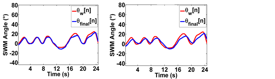 (c) (d)
Figure 3. Various ratios of βgyro:βaccel plotted for (a) 10:90; (b) 90:10; (c) 99:1; (d) 99.5:0.5.
and deaths with minimal cost to drivers and car manufacturers.
Future work will involve embedding this technology into vehicle steering wheels to further the potential for its eventual integration into vehicular systems. In addition, the development of a steering mount implementation will be researched to provide an easy alternative for drivers whose vehicles do not come with such technologies. Other future work includes the investigation of alternate inertial components by manufacturer to further optimize cost/performance output for the end user.
5.1. Slight Variations between
 and
and

Slight variations existed between
 and
and
 which could be observed in the high velocity rotation testing performed in 3.5. The
 signal which comprised mostly of gyroscope data exhibited “ears” at the beginning and end of very sudden turns during periods of high and rapidly changing angular velocities (Figure 4(a)). Overall, the
 readings maintained high accuracy, even during sudden movements. Although such unusually high velocity steering activities are not expected to occur except during the most extreme driving cases, possibly involving road accidents. Despite this, the readings of
 maintained high accuracy.
5.2. Rotations beyond 360˚
Because most steering wheels rotate through more than 360˚, predictive readings can be used to compensate for this effect. A tiny microcontroller for example can be used to adjust for this. If a range of 361˚ to 720˚ are the base readings of the sensor, any measurements beyond a full counter-clockwise rotation would adaptively read between 0˚ to 360˚ and any measurements beyond a full clockwise rotation would adaptively read between 721˚ to 1080˚.
5.3. Comparison of the Proposed Method with the Earlier Accelerometer-Based Method
The proposed method yielded a more noise resistant method of SWM monitoring when compared to the previous accelerometer-based method [20] . The use of a low pass filter is effective against vehicle and road noises using the previous method, however, if a practical application of SWM monitoring calls for no phase shiftingmargin, then the current fusion method might be better suited. Phase shifted signals retain their accurate waveforms, however time delay could occur if filtered improperly. The currently proposed method did not demonstrate any need for filtering, even during real road trials.
The unfiltered accelerometer-based method, while more prone to linear vibration noise than the current method, is very effective in drowsy driving simulation tasks especially as it is dangerous to place sleep deprived subjects on the highway.
The benefit of the currently proposed system is the enhancement of the strengths and weaknesses of two completely different sensors in a method whereby they both work more effectively. The use of a gyroscope for the majority of the SWM data eliminates the problem of linear vibrations due to the gyroscopes insensitivity to such data. It is seen that both methods are effective and accurate for their individually specific tasks. The current method was not prone to road noise, engine noises, and other vehicle noises.
 (a) (b)
Figure 4. (a) High speed SWM outputs remained highly accurate representations of ground truth steering movements; (b) The final signal (right) matches the potentiometer signal.
6. Conclusion
This study demonstrated that the effective fusion of a simple gyroscope and accelerometer can be used to accurately monitor SWM for drowsy driving activities including sudden corrections and wide angle corrections. The efficacy of the method was confirmed by comparing the SWM estimates generated by the method with actual SWM readings collected from the steering-wheel potentiometer which yielded high correlation. The high correlation suggests that the method could be used as a direct replacement of other SWM measures for the implementation of SWM-based drowsy detection algorithms.
References
- Rau, P. (1996) NHTSA’s Drowsy Driver Research Program. National Highway Traffic Safety Administration. Washington DC.
- Vanlaar, W., Simpson, H., Mayhew, D. and Robertson, R. (2008) Fatigued and Drowsy Driving: A Survey of Attitudes, Opinions and Behaviors. Journal of Safety Research, 39, 303-309. http://dx.doi.org/10.1016/j.jsr.2007.12.007
- Connor, J., Norton, R., Ameratunga, S., Robinson, E., Civil, I., Dunn, R., Bailey, J. and Jackson, R. (2002) Driver Sleepiness and Risk of Serious Injury to Car Occupants: Population Based Case Control Study. BMJ, 324, 1125. http://dx.doi.org/10.1136/bmj.324.7346.1125
- Hamblin, P. (1987) Lorry Driver’s Time Habits in Work and Their Involvement in Traffic Accidents. Ergonomics, 30, 1323-1333. http://dx.doi.org/10.1080/00140138708966026
- Maclean, A.W., Davies, D.R. and Thiele, K. (2003) The Hazards and Prevention of Driving While Sleepy. Sleep Medicine Reviews, 7, 507-521. http://dx.doi.org/10.1016/S1087-0792(03)90004-9
- Kim, J.Y., Jeong, C.H., Jung, M.J., Park, J.H. and Jung, D.H. (2013) Highly Reliable Driving Workload Analysis Using Driver Electroencephalogram (EEG) Activities during Driving. International Journal of Automotive Technology, 14, 965-970. http://dx.doi.org/10.1007/s12239-013-0106-z
- Ogawa, K. and Shimotani, M. (1997) A Drowsiness Detection system. Mitsubishi Electric Advance, 78, 13-16.
- Wierwille, W. (1999) Historical Perspective on Slow Eyelid Closure: Whence PERCLOS? In: Technical Proceedings of Ocular Measures of Driver Alertness Conference, Herndon, VA (FHWA Technical Report No. MC-99-136), Federal Highway Administration, Office of Motor Carrier and Highway Safety, Washington DC, 31-53.
- Bowman, D.S., Schaudt, W.A. and Hanowski, R.J. (2012) Advances in Drowsy Driver Assistance Systems through Data Fusion. In: Handbook of Intelligent Vehicles, Springer, Berlin, 895-912.
- Wierwille, W., Hanowski, R., Olson, R., Dinges, D., Price, N., Maislin, G., Powell IV, J., Ecker, A., Mallis, M. and Szuba, M. (2003) NHTSA Drowsy Driver Detection and Interface Project-Final Report. Contract No. DTNH22-D- 00-07007, Task Order, 1.
- Fukuda, J., Akutsu, E. and Aoki, K. (1995) An Estimation of Driver’s Drowsiness Level Using Interval of Steering Adjustment for Lane Keeping. JSAE Review, 16, 197-199. http://dx.doi.org/10.1016/0389-4304(94)00070-A
- Elling, M. and Sherman, P. (1994) Evaluation of Steering Wheel Measures for Drowsy Drivers. Proceedings of the 27th ISATA, Aachen, 31 October-4 November 1994, 207-214.
- Thiffault, P. and Bergeron, J. (2003) Monotony of Road Environment and Driver Fatigue: A Simulator Study. Accident Analysis & Prevention, 35, 381-391. http://dx.doi.org/10.1016/S0001-4575(02)00014-3
- Eskandarian, A. and Mortazavi, A. (2007) Evaluation of a Smart Algorithm for Commercial Vehicle Driver Drowsi- ness Detection. Proceedings of IEEE Conference on Intelligent Vehicles Symposium, Istanbul, 13-15 June 2007, 553- 559.
- Yabuta, K., Iizuka, H., Yanagishima, T., Kataoka, Y. and Seno, T. (1985) The Development of Drowsiness Warning De- vices. Proceedings of the 10th International Technical Conference on Experimental Safety Vehicles (ESV), Oxford, England, 10, 282-288.
- Sayed, R. and Eskandarian, A. (2001) Unobtrusive Drowsiness Detection by Neural Network Learning of Driver Steer- ing. Proceedings of the Institution of Mechanical Engineers, Part D: Journal of Automobile Engineering, 215, 969-975. http://dx.doi.org/10.1243/0954407011528536
- Luinge, H., Veltink, P. and Baten, C. (1999) Estimating Orientation with Gyroscopes and Accelerometers. Technology and Health Care, 7, 455-459.
- Lee, H., Ryu, S. and Lee, J. (2009) Optimal Posture of Mobile Inverted Pendulum Using a Single Gyroscope and Tilt Sensor. Proceedings of ICCAS-SICE, Fukuoka, 18-21 August 2009, 865-870.
- Greene, M. (1996) A Solid State Attitude Heading Reference System for General Aviation. Proceedings of IEEE Conference on Emerging Technologies and Factory Automation, Kauai, 18-21 November 1996, 413-417.
- Lawoyin, S.A., Fei, D.Y. and Bai, O. (2014) Accelerometer-Based Steering Wheel Movement Monitoring for Drowsy Driving Detection. Proceedings of the Institution of Mechanical Engineers, Part D: Journal of Automobile Engineering, Published Online 31 October 2014. http://dx.doi.org/10.1177/0954407014536148
- Sakaguchi, T., Kanamori, T. and Katayose, H. (1996) Human Motion Capture by Integrating Gyroscopes and Accelerometers. Proceedings of IEEE/SICE/RSJ International Conference on Multisensor Fusion and Integration for Intelligent Systems, Washington DC, 8-11 December 1996, 470-475.