Optics and Photonics Journal
Vol.2 No.1(2012), Article ID:18252,5 pages DOI:10.4236/opj.2012.21002
Behavioral Variations of Gain and NF Owing to Configurations and Pumping Powers
Hafr Al-Batin Community College (HBCC), King Fahd University of Petroleum and Minerals (KFUPM), Dhahran, Saudi Arabia
Email: Bouzid@hbcc.edu.sa
Received November 29, 2011; revised January 5, 2012; accepted January 12, 2012
Keywords: double pass; single pass; erbium doped fiber; configuration; pumping power
ABSTRACT
Six configurations are proposed in this paper to explore the gain and noise figure (NF) variations under the pumping power effect. I propose a new investigation of gain and NF at different EDFA configurations. Configurations such as SPSS, DPSS, DPSSF, TPDS, TPDSF, and QPDSF are designed, investigated and compared. A continuous progress of gain values is observed from SPSS to QPDSF, and a change of NF values related to configurations is recorded. The NF variations show different behaviors at different configurations. High gain of 59.49 dB and low NF value of 4.22 dB are recorded for the QPDSF configuration and low gain and low NF are recorded for the SPSS configuration.
1. Introduction
EDFA is a crucial milestone in optical communication systems and wide growing internet. The progressive development of EDFA since its early stage at the end of eightieth is showing a continuous progress at the two levels of EDFA knowledge, theoretical and experimental. EDFA is an important part in the long haul optical fiber communication, and it is considered as another interesting research topic for laser phenomena of spontaneous and stimulated emission, where interaction of matter-lightmatter still in its early stage.
Fiber to the home will guide the future changes of communication in the near future. Laser with the stimulated and spontaneous emission are considered to be the main factor in the next quantum revolution. Let us think how terabits transmission can be carried out without fiber optics or fiber amplifier? How the narrow band of electronics can be handling the wide broad band of communication systems? At the beneath of the laser phenomena there are many promising future development and new discoveries that can be conditionally achieved. Optical amplifier and lasers are used nearly in all the wide spectrum of science such as medicine, military, education and manufacturing.
Research in optical communication systems is growing daily. In addition, the obligation for efficient systems to fulfill the practical need of communication for high capacity and high speed is extremely demanded due to the fast growing of high speed and high capacity transmission. Highly efficient and stable EDFAs is playing a milestone role in this crucial era.
The lack of entire description of behavioral study of gain and NF at different configurations in the published papers will affect the fast growing of optical amplifier and reduce its effectiveness. Most of the published papers are focusing on NF and efficiency [1], gain and gain flattening [2-5], and optimization of pumping power [6] without any research papers which, focuses on the description of the complete behavioral variations and trends of EDFA gain and NF at different configurations.
All factors affecting the EDFA are needed to be elaborated and investigated to enhance the amplification outputs. Focusing on improvement of gain and noise figure, the devised and optimized configuration is to establish a wide and flat EDFA gain [2-5], and to discover an efficient EDFA at all levels. The obligation for an efficient EDFA is to fulfill the practical need of communication, with high capacity and high speed.
The EDFA description at different configurations is rarely found in the published papers [7], and the use of the entire physical phenomena to describe, illustrate, and interpret the variations of gain and NF at different configurations is highly required to understand their trends at large-scale.
In this paper general descriptions with illustrations and analysis are performed based on the studies of six different configurations: single pass single stage (SPSS), double pass single stage (DPSS), double pass single stage with filter (DPSSF), triple pass double stage (TPDS), triple pass double stage with filter (TPDSF) and quadruple pass double stage with filter (QPDSF) [8].
2. Experiment Setup and Discussion of Results
The used erbium-doped fiber in this experiment is characterized by: NA of 0.27 cutoff wavelength of 840 nm, peak absorption at the signal 1527 nm wavelength of 6 dB/m, erbium concentration of 440 ppm, and Er3+ core doped in silica/germania. The New port, tunable band pass filter (TBF) is mechanically tuned with a pass-band of 1 nm, an insertion loss of 1.5 dB at the tuned wavelength, and a tuning range limited to 45 nm from 1520 to 1565 nm. The Tunable Laser Source (TLS) is a continuous wavelength source of the 1550 nm input signal power, and the wavelength division multiplexer (WDM) is to merge both 980 nm pump and 1550 nm signal in EDF. The signal will be reacted with stimulated emission and amplified spontaneous emission (ASE) where at the output the ASE and the stimulated signal will be displayed. The filter will eliminate almost all ASE; the OSA displays the amplified signal with small portion of ASE at the bottom of the signal.
The six configurations were shown in Figure 1(a) SPSS: single pass single stage, Figure 1(b) DPSS: double pass single stage, Figure 1(c) DPSSF: double pass single stage with filter, Figure 1(d) TPDS: triple pass double
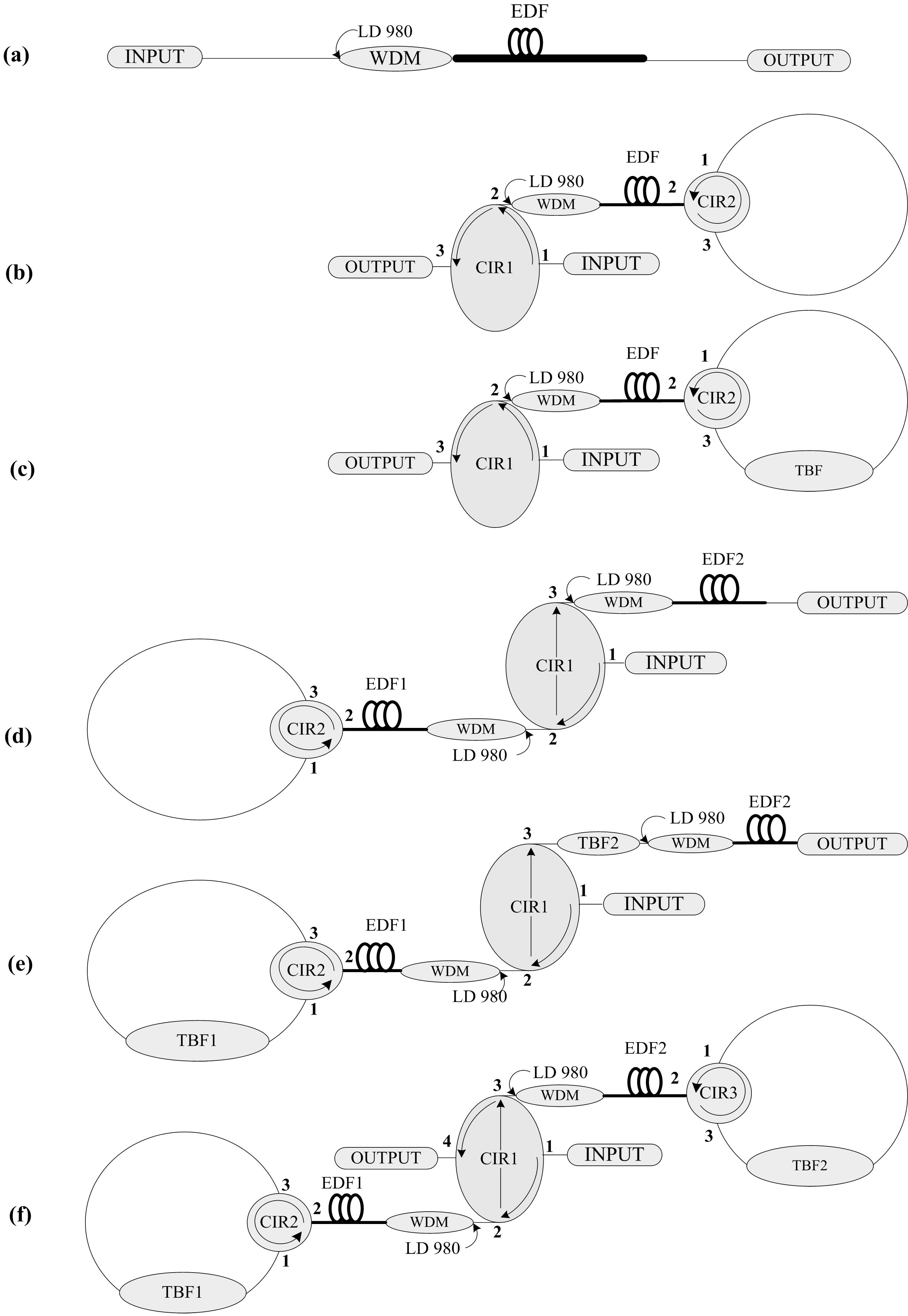
Figure 1. Experimental configurations of EDFA: (a) single pass single stage (SPSS); (b) double pass single stage (DPSS); (c) double pass single stage with filter (DPSSF); (d) triple pass double stage (TPDS); (e) triple pass double stage with filter (TPDSF) and (f) quadruple pass double stage with filter (QPDSF). TBF: tunable bandpass filter, CIR: circulator, EDF: erbium-doped Fiber, LD: laser diode, and WDM: wavelength division multiplexing, INPUT: tunable laser source, and OUTPUT: optical spectrum analyzer.
stage, Figure 1(d) TPDSF: triple pass double stage with filter, and QPDSF: quadruple pass double stage with filter. The difference between these configurations is owing to the additions of TBF and the second stage which can be single pass or double pass. The circulators are used as loop back where port1 and 3 are spliced and the TBF is incorporated between these ports to suppress and eliminate the unwanted ASE. The Key role of TBF in this continuous increase of gain is impressive and crucial where stimulated emission will strongly amplify the signal.
Due the large number of configurations used in these experiments, we will describe only the signal in the QPDSF configuration. The configuration in Figure 1(f) showed that each turn consistently gave a signal attenuation of 12 dB, this loss is due to three circulators, two TBF filters, and two WDMs. Thus, the amplified signal will propagate through the CIR1 from port1 to port2 then travel through EDF1; the signal will be affected by the first amplification from EDF1, through port2 into port3 of CIR2, passing through the first TBF1 filter into port1 and back to port2 to be amplified during the second pass by EDF1 into port2 of CIR1, and therefore will propagate again in the second stage through EDF2, CIR3, and TBF2 for the third and fourth passes. The output signal power was displayed through the OSA from port4 of CIR1. Traveling from port1 to port4 of CIR1, the signal will be affected by four amplifications during the four passes, or, as we mentioned, the quadruple pass double stage with filter configuration [8].
Figure 2 shows gain on dB versus configurations and pumping power. The input signal power is at 1550 nm wavelength and –50 dBm only the SPSS. From the 3D graph, all the six configurations show an increase of gain at the changing of configurations from SPSS, DPSS, DPSSF, TPDSF and QPDSF. Except for the TPDS without filter, which shows a lower gain compared to DPSSF and TPDSF.
It can be seen clearly, by following the variations of gain values versus configurations, at lower pump power of 10 mW, the gain is varied at different configurations where a shift between 9.65 and 45 dB of the gain values is recorded for SPSS and QPDSF respectively. At higher pumping power of 90 mW the gain is shifted owing to configurations change from 20.04 to 59.49 dB. All these results are at 1550 nm input signal power and –50 dBm except the SPSS. This good result shows clearly the varied configurations, the filter, and the double pass impact on the gain values. So, with the change of configuration from SPSS to QPDSF, the gain is increased to 45 dB at low pumping power. The gain gap between the SPSS and QPDSF reach to 39.45 dB at high pump power.
Go in details for the shown results in the figure. The SPSS records the lowest gain where the QPDSF records the highest one. At this level of explanation, the effect of the configurations type is very crucial where the gain gap between the SPSS and QPDSF reach approximately 35.83 dB at 10 mW pump power. It is evident that the effect of the pumping power and configuration with filter are effective for the gain enhancement. It is also observed, that the DPSSF has a higher gain compared with TPDS where single stage has higher gain compared to double stage. I think, the role of filter in the design is certainly crucial and principal in this reversed phenomenon. In this case it is recorded that adding single stage single pass to the double pass configuration will reduce the gain.
Figure 3 shows experimental NF versus configura-
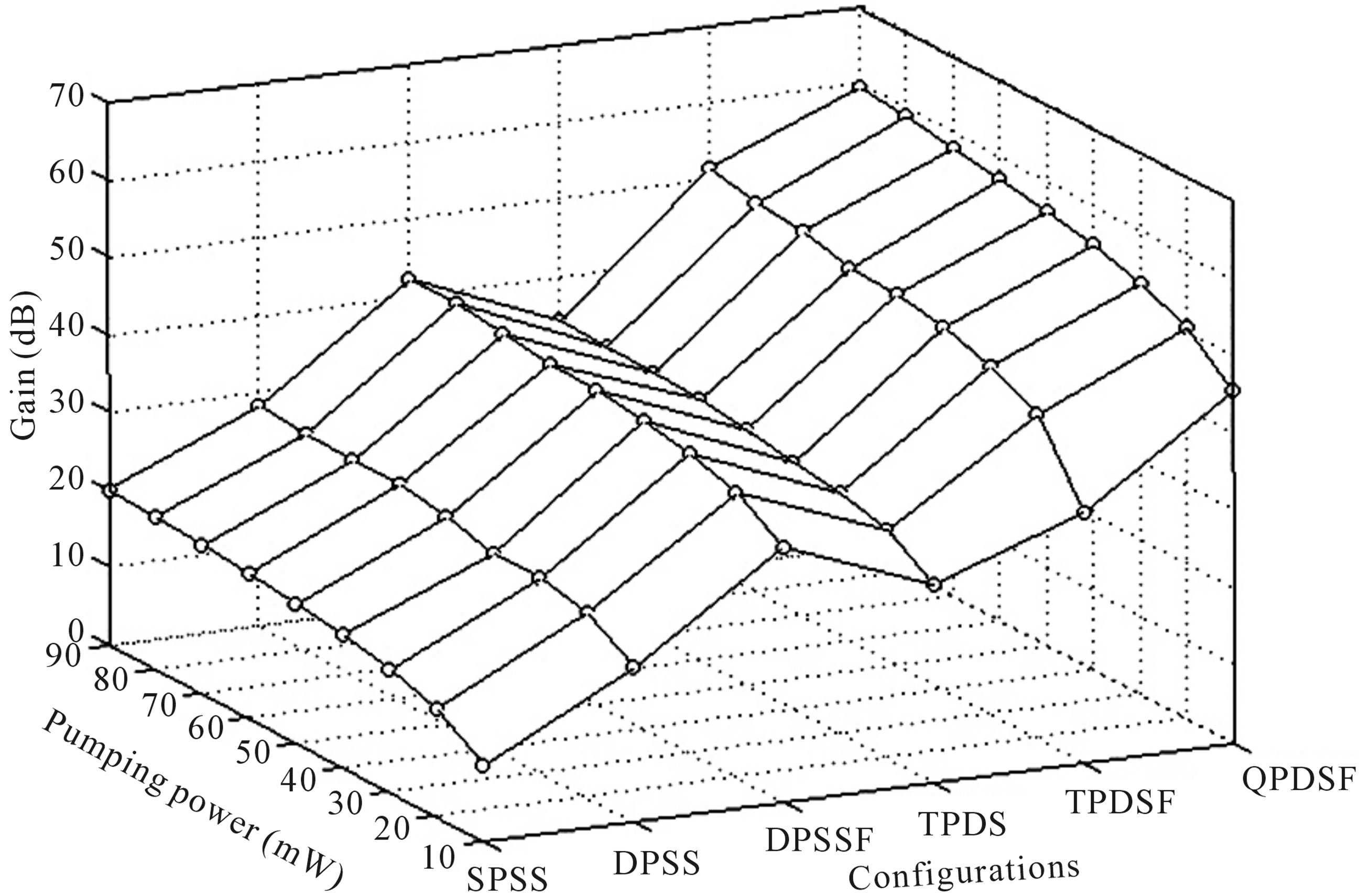
Figure 2. Experimental gain versus configurations and pumping power at 1550 nm wavelength at –50 dBm input signal power. SPSS: single pass single stage, DPSS: double pass single stage, DPSSF: double pass single stage with filter, TPDS: triple pass double stage, TPDSF: triple pass double stage with filter, and QPDSF: quadruple pass double stage with filter.
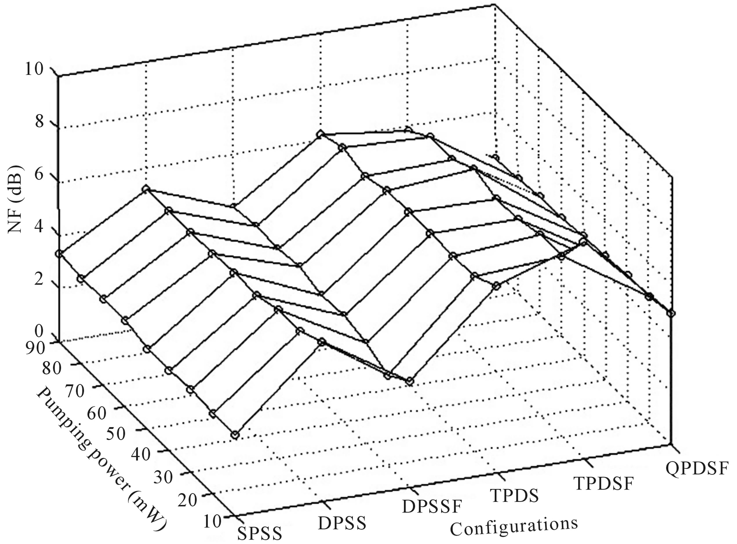
Figure 3. Experimental NF versus configurations and pumping power at 1550 nm wavelength at −50 dBm input signal power. SPSS: single pass single stage, DPSS: double pass single stage, DPSSF: double pass single stage with filter, TPDS: triple pass double stage, TPDSF: triple pass double stage with filter, and QPDSF: quadruple pass double stage with filter.
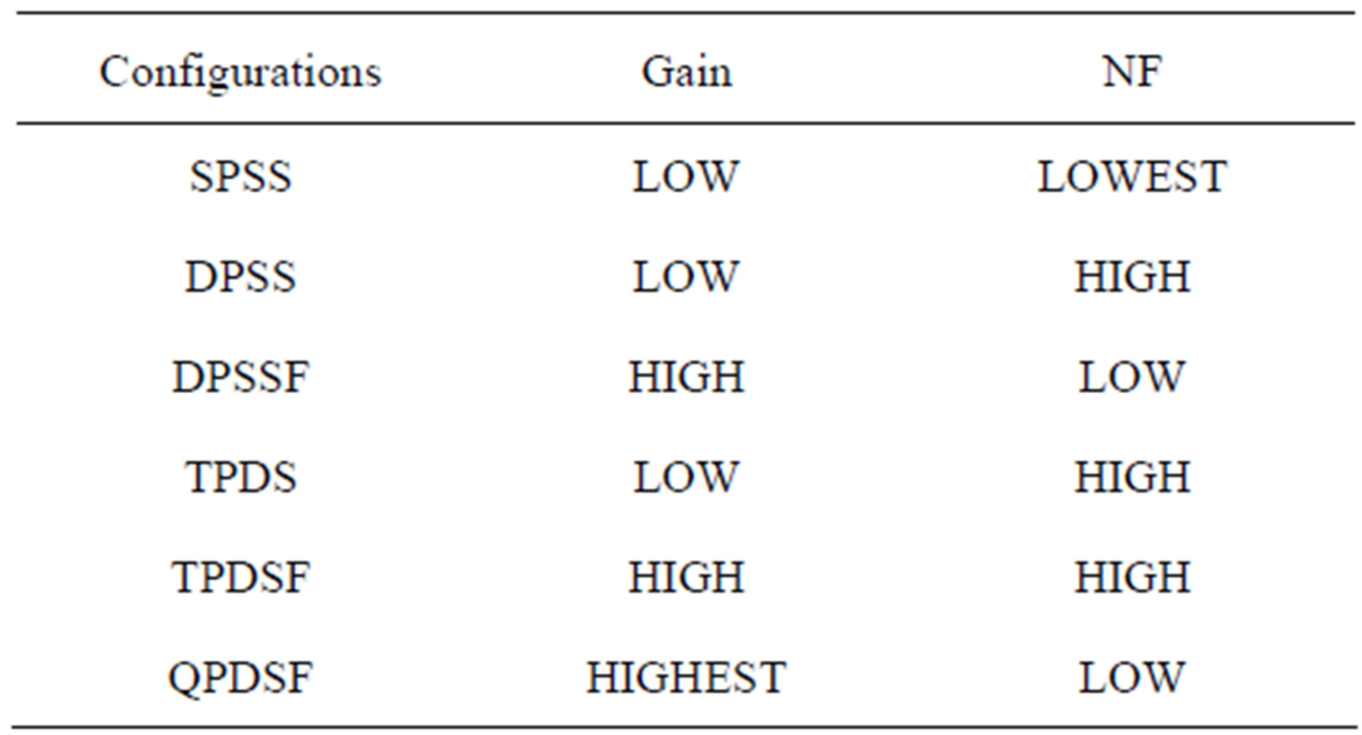
Table 1. Gain and NF variations due to configuration.
tions and pumping power at input signal power of 1550 nm wavelengths and −50 dBm except SPSS. It is evident that the NF is decreased at specific configurations and increased at others. The 3D graph shows clearly that the NF is decreased at three configurations. It is also evident that the NF is bellow 5 dB for the SPSS, DPSSF, and QPDSF configurations, and above 5 dB for the DPSS, TPDS, and TPDSF configurations. The TPDS and TPDSF show the highest NF compared with the other configurations.
It can be noted the effect of adding the single pass stage to the double pass on increasing of noise figure. In the double stage double pass the TBF filter is affecting the QPDSF and the DPSSF and enhance their NF. The configuration SPSS records the lowest NF with the lowest gain, QPDSF records the highest gain. This can be related to the multi factors that have been included such as: double pass, double stage, and the filter positioned between the two ports of the circulator. It is clearly
shown in this paper, that the configuration structure and the filter are crucial in the variation of the gain and NF. In particular, high gain can be generated simply with simple modification related to the design structure. QPDSF records 59.49 dB gain and 4.22 dB NF. This result can be increased higher with fifth or sixth passes and higher pump power. Table 1 shows the description and the comparison of gain and NF at different configurations.
3. Conclusion
The configurations SPSS, DPSS, DPSSF, TPDS, TPDSF, and QPDSF were exposed to the same conditions of input signal power wavelength and different pumping power. The full investigation of gain and NF shows high gain of 59.49 dB and low NF of 4.22 dB values of QPDSF configuration. Gain and NF were profoundly described and clearly investigated using both 3D and 2D graphs display. A continuous increasing of gain values was demonstrated. The gain progress was recorded from SPSS, DPSS, DPSSF, TPDS, TPDSF, to QPDSF configurations. A variation of NF related to different configurations was proved and demonstrated. The TBF positioned in the between the circulator ports, configurations structure, and pumping power are a principal factors for gain and NF control.
4. Acknowledgments
The author wishes to acknowledge UPM, MMU (Malaysia) and HBCC/KFUPM (Saudi Arabia) for their support in providing the various facilities utilized in the presentation of this paper.
REFERENCES
- A. C. Çokrak and A. Altuncu, “Gain and Noise Figure Performance of Erbium-Doped Fiber Amplifiers,” Journal of Electrical & Electronics Engineering, Vol. 4, No. 2, 2004, pp. 1111-1122.
- B. Bouzid, B. M. Ali and M. K. Abdullah. “A High Gain EDFA Design Using Double Pass Amplification with a Band-Pass Filter,” Photonics Technology Letters, Vol. 15, No. 9, 2003, pp. 1195-1197. doi:10.1109/LPT.2003.814901
- Y. B. Lu and P. L. Chu, “Gain Flattening by Using DualCore Fiber in Erbium-Doped Fiber Amplifier,” IEEE Photonics Technology Letters, Vol. 12, No. 12, 2000, pp. 1616-1617 .
- A. Mori, T. Sakamoto, K. Shikano, K. Kobayashi, K. Hoshino and M. Shimizu, “Gain Flattened Er3+-Doped Tellurite Fiber Amplifier for WDM Signals in the 1581 - 1616 nm Wavelength Region,” Electronics Letters, Vol. 36, No. 36, 2000, pp. 621-622.
- C. Yang, “Design and Simulation of Gain-Flattened Ultra Wideband Fiber Amplifiers Covering S-, C-, and Lbands,” Ph. D Thesis, The University of North Carolina at Charlotte, Charlotte, 2003.
- M. A. Mahdi, K. A. Khairi, B. Bouzid and M. K. Abdullah “Optimum Pumping Scheme of Dual-Stage TriplePass Erbium-Doped Fiber Amplifier,” IEEE Photonics Technology Letters, Vol. 16, No. 2, 2004, p. 419. doi:10.1109/LPT.2003.821059
- A. Sellami, K. Al-Khateeb and B. Belloui, “The Influence of EDFA’s Configuration on the Behavioral Trends of Gain,” International Conference on Computer and Management, Kuala Lumpur, 9-11 May 2006, pp. 853-856.
- B. Bouzid, “High-Gain and Low-Noise-Figure ErbiumDoped Fiber Amplifier Employing Dual Stage Quadruple Pass Technique,” Optical Review, Vol. 17, No. 3, 2010, pp. 100-102.