Journal of Encapsulation and Adsorption Sciences
Vol.2 No.3(2012), Article ID:23077,6 pages DOI:10.4236/jeas.2012.23005
On the Rupture of a Liquid Film Formed on a Droplet Crossing a Horizontal Liquid-Liquid Interface
Faculty for Production and Management Trebinje, University in East Sarajevo, Republic of Srpska, Bosnia and Herzegovina
Email: mitrovic@tebam.de
Received June 15, 2012; revised July 21, 2012; accepted August 19, 2012
Keywords: Droplet; Interface; Thin Film; Film Rupture; Encapsulation
ABSTRACT
A gravity droplet crossing a liquid-liquid interface is covered on the forefront with a film of the leaving liquid phase. The film thickness is not homogeneous over the droplet surface, and it reduces as the droplet penetrates the interface, particularly in the stretched area where it then ruptures. An expression for the film thickness in the stretched region is deduced from a force balance. The film rupture is expected to occur at a droplet position when the normal stress in the stretched film reaches the tensile strength of the liquid. By using some experimental data from literature the expression delivers 26 nm for the film thickness at rupture, while Burrill and Woods [1] obtained experimentally values between 30 nm and 50 nm.
1. Introduction
Dynamics of thin fluid films governs kinetics of many processes like coalescence and encapsulation of particles. Prior to coalescence the fluid separating the particles must be squeezed out and the remaining film ruptured. The flow in the film is mostly treated on the basis of the lubrication model, see e.g. Davis et al. [2], Chesters [3], Klaseboer et al. [4], Bazhlekov et al. [5]. From this model, equations for calculating the film thickness as funcion of time were derived, but a determination of the film thickness at the rupture instant is not possible. The situation is similar with encapsulation of a particle. The particle to be encapsulated is forced to cross a thin layer of encapsulating material whereby a thin film of this material envelops the particle, see e.g. Massoth et al. [6] and Abkarian et al. [7]. In contrast to coalescence, the film enveloping the particle should be stable and posses a homogeneous thickness.
In a recent paper Oldenziel et al. [8] present experimental results on the behaviour of liquid droplets at a two-liquid interface, mainly focusing on the time history of the film covering the upper part of the droplet. The movement of the droplet is provided by gravity; the soft interaction of the originally spherical droplet with the interface flattens the sphere to a rotational ellipsoid. The thickness of the film on the droplet is not homogeneous; it is maximal at the droplet vertex and decreases radially outwards. The film rupture was observed to occur in the outer region, and not at the droplet vertex. This information is important in context with the estimation of the probability that the droplet during the interaction time mix with the upper liquid layer, being miscible with the droplet liquid. The time history of the layer observed in the experiments shows a spatial asymmetry, caused by experimental reality. The reported results also provide important insights into encapsulation and collision process e.g. of two droplets of different sizes. They are in agreement with the theoretical models; several such models have been analysed in the review paper by Chan et al. [9], and the reader is referred to this source, also for further references.
In addition to the film shape, of certain importance is also the question of the thickness of the film at the instant of its rupture, both in coalescence and encapsulating processes. The present paper provides a model for estimation of the thickness of this film at the rupture. The model is based on a static force balance of the film formed on a droplet crossing a horizontal liquid-liquid interface. The droplet is assumed to be an oblate spheroid formed by revolution of an ellipse about its minor (vertical) axis.
2. The Physical Model
The physical system consists of two sufficiently thick horizontal liquid layers of different densities, Figure 1(a). In the lower layer there is a liquid droplet of a lighter (upper) phase that moves upwards by gravity. As the droplet approaches the upper phase, it deforms the originally even interface, penetrates that phase, but remains at first separated from it by a thin film of the heavier (lower) phase. Since the droplet is not rigid, it also becomes deformed and changes its shape from nearly spherical to a flattened ellipsoid, Figure 1(b). As the droplet penetrates further the lighter phase, the liquid layer enveloping the droplet on its upper part thins down to a certain thickness when it then ruptures, and the droplet liquid becomes sucked by the lighter phase.
Many experiments dealing with such penetration phenomena have shown that the droplet shape depends on the system properties and the velocity the droplet approaches the interface, see e.g. Chan et al. [9]. The thickness of the liquid layer is not uniform over the droplet surface, and at certain distance from the vertical symmetry axis, near the inflection line of the interface separating the continuous phases, the liquid film is extremely thin. This hinders the outflow of the upper portion of the film (bottle neck effect). The movement of the droplet results in a continuous thinning of the film in its outer region which subsequently ruptures.
2.1. The Buoyancy Force
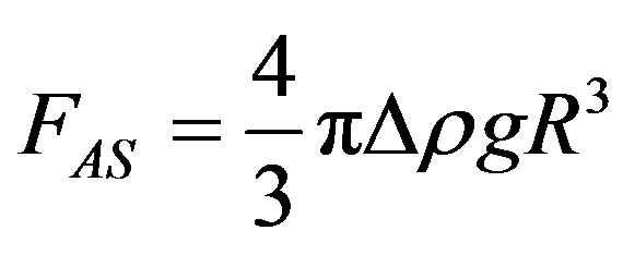
Referring to Figure 1(a), the Archimedes force causing the droplet to ascend is
 (1)
(1)
where R is an equivalent radius of the droplet taken as a sphere.
Prior to interaction start with the upper liquid phase and deformation of the interface, the whole droplet volume is involved and causes this force. When the droplet is in interaction with the upper phase and is deformed as illustrated in Figure 1(b), the situation changes and the buoyancy force depends on the position of the droplet relative to the undisturbed interface. It seems reasonable to consider the droplet volume below the plane placed a distance m above the horizontal symmetry plane of the ellipsoid to cause the Archimedes force. The position of this plane is determined by the position of the horizontal circular line connecting the minima of the film thickness.
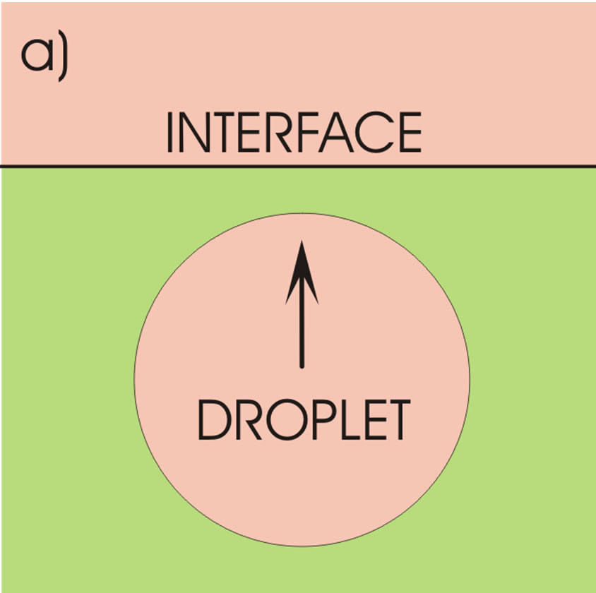
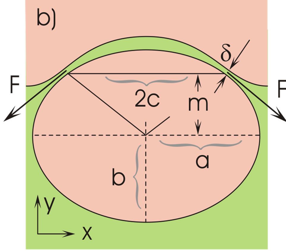
Figure 1. Ascending liquid droplet in a continuous liquid (a) and its deformation at the interface (b).
With this notion and the assumption of an ideal (rotation-symmetric) ellipsoid with respect to its vertical axis, described parametrically,
 , (2)
, (2)
the volume V causing the buoyancy is
 (3)
(3)
The Archimedes force,  , may thus be expressed as
 . (4)
. (4)
For m = b the ellipsoid is surrounded by the heavier (lower) liquid and its total volume is involved in the buoyancy force.
2.2. The Geometry of the Droplet
The geometrical parameters of the ellipsoidal droplet depend on the process parameters. The movement of the droplet is assumed to be very slow and the dynamical effects are neglected. The shape of the droplet is then caused only by the force FAE which generates certain curvature of the droplet surface; the maximum curvature is expected in the horizontal symmetry plane, at y = 0. The local curvature of the ellipse is
 , (5)
, (5)
which for y = 0, that is for t = 0, gives the curvature  of the ellipsoid surface in the vertical plane at y = 0,
 (6)
(6)
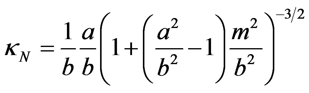
The curvature of the ellipsoid surface in the horizontal plane y = 0 is , and the average curvature is
 (7)
(7)
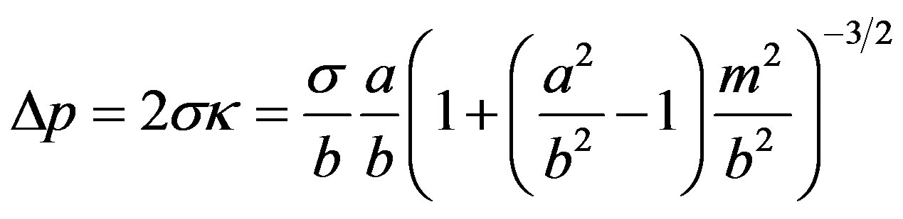
This curvature is used to obtain the ratio of the main ellipsoid axes. Neglecting the capillary pressure at x = 0, y = b, the force balance at x = a, y = 0,
 (8)
(8)
delivers
 ,
,  , (9)
, (9)
where the Bond number B0 is defined with the axis b of the ellipsoid as the characteristic length. Obtaining b from experiments, Equation (9) determines the other axis, a; for ,
, .
.
2.3. The Film Thickness at Rupture
The movement of the droplet penetrating the interface is a complex process whose treatment requires a detailed analysis of fluid dynamics with overlapped interfacial effects. The so called lubrication model is mostly used for treatment of such or similar problems, see e.g. [2-5,9] for details. However, the dynamical effects are getting weaker as the film thins and may be neglected immediately prior to film rupture in comparison to static effects; the film rupture is viewed as follows.
As the droplet moves upwards, the liquid film covering the droplet becomes stretched particularly in its outer (thinnest) region, and the thickness d decreases, Figure 1(b). This impedes the liquid above the droplet from outflow. In addition, the droplet penetration increases the capillary pressure in the region of the inflection line of the interface, Figure 2. At this line, the tangential curvature of the bell-shaped interface is zero, ; its normal curvature
  may be obtained from the equation of the ellipse, for small d. Equation (5) then gives, for
 :
:
 (10)
(10)
Using the average
for the capillary pressure one obtains
 (11)
(11)
This pressure also retards the film drainage. It is larger than the capillary pressure in the film near the vertical axis ( ) which may support formation a concave-convex interface in that region.
To obtain an expression for the thickness d at the instant of the film rupture we adopt the following model assumptions:
a) The liquid film is a fluid sheet able of flowing and stretching.
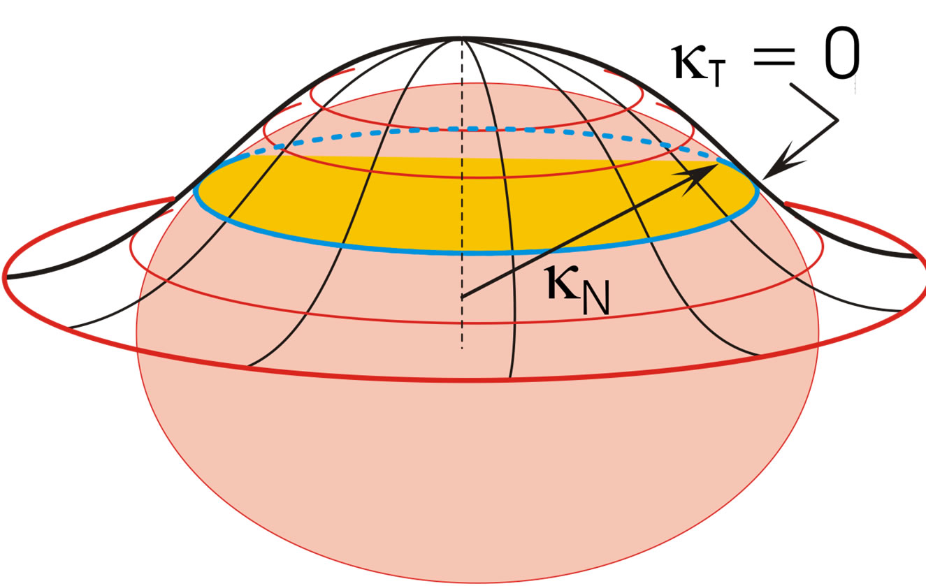
Figure 2. Bell-shaped interface generated by droplet penetration into upper continuous liquid phase. The inflection (blue) line is at distance m from the horizontal droplet symmetry plane, Figure 1(b).
b) The force FAE given in Equation (4) presses the liquid film above the droplet against the lighter upper phase, and a certain amount of the film liquid flows out across the gap (thickness d) at the inflection line, Figures 1(b) and 2. Due to the upwards droplet movement the liquid in this gap is continuously stretched and exposed to the action of a steadily increasing capillary pressure, decreasing m in Equation (11). The film stretching arises both verti cally and azimuthally (increasing c in Figure 1(b)).
c) The liquid film is held together by molecular interaction in the film cross-section. At a large film thickness the number of molecules in the film cross section is large and the resulting force arising from the molecular interactions prevents the film rupture (the origin of the molecular interaction is not the subject of this paper).
d) As the film thins, the number of molecules occupying the cross-section decreases; at certain film thickness the stretching force overcomes the molecular interaction, and the film ruptures.
Taking the sketched process sufficiently slow to neglect dynamical effects and disregarding capillary effects, one obtains the following force balance for the film cross-section along the inflection line. The projection of the buoyancy force FAE on the tangent at the inflection line (Figure 2) in the direction of the film flow,
 (12)
(12)
 (13)
(13)
 (14)
(14)
where , is balanced by the internal, resulting molecular force in the film that may be stated in terms of the tensile strength of the liquid. Denoting the tensile strength by Ã, the force balance may be written as
 (15)
(15)
hence
 (16)
(16)
 (17)
(17)
 (18)
(18)
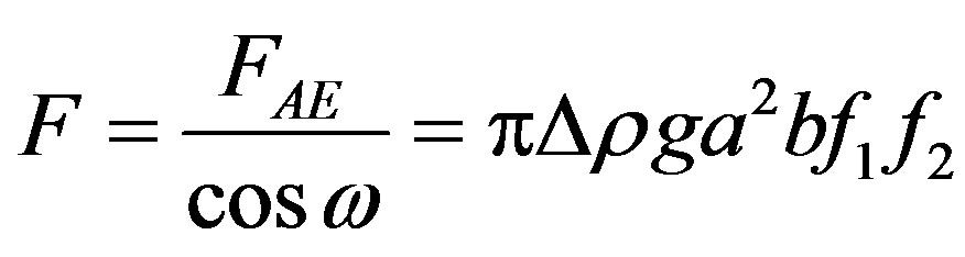
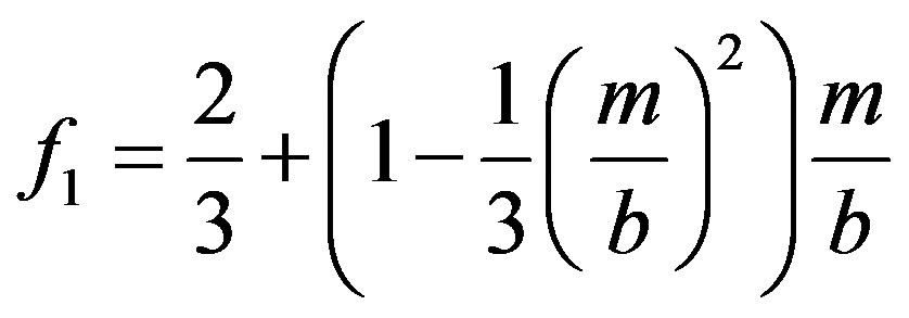
Using Equation (9), Equation (16) can be written as
 (19)
(19)
The shape function F contains only the geometrical parameters of the ellipsoid, but it depends implicitly on the physical properties via the ratio  according to Equation (9). For m = 0 it is
  and
and
 (20)
(20)
which is valid for a particular position of the droplets, Figure 1(b) .
3. Illustration of Results
Figure 3 illustrates Equation (9), the shape of the droplet. The ratio  of the ellipsoid axes increases almost linearly with B0.
Figure 4 quantifies Equation (11) for chosen values of the axes ratio . The pressure
  enhances the thinning of the film in the region of the inflection line of the interface and resists the outflow of the liquid locked above the droplet. This effect is larger at larger B0.
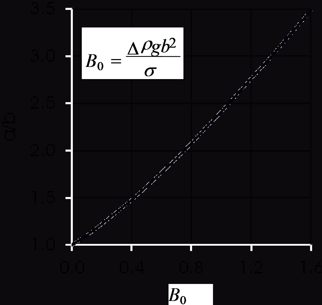
Figure 3. Effect of Bond number on droplet flattening according to Equation (9).
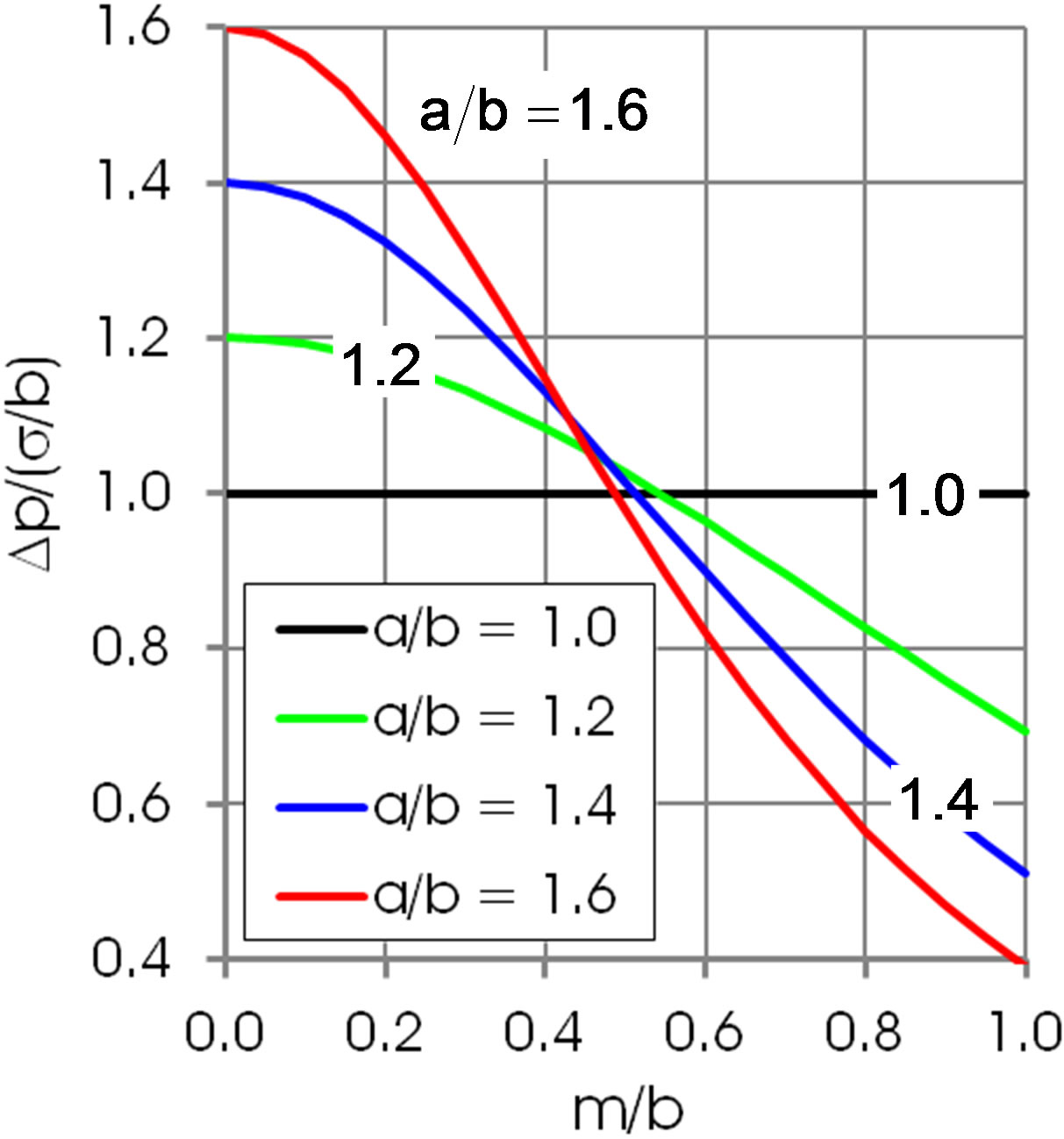
Figure 4. Capillary pressure on the inflection line acts against the outflow of the liquid locked above the droplet, Equation (11).
Figures 5 and 6 show the shape function F for selected values of . This ratio does not that sensitively affect the function F in regions of practical importance, values of
  and
and . In connection with Equation (19) one expects a larger film thick
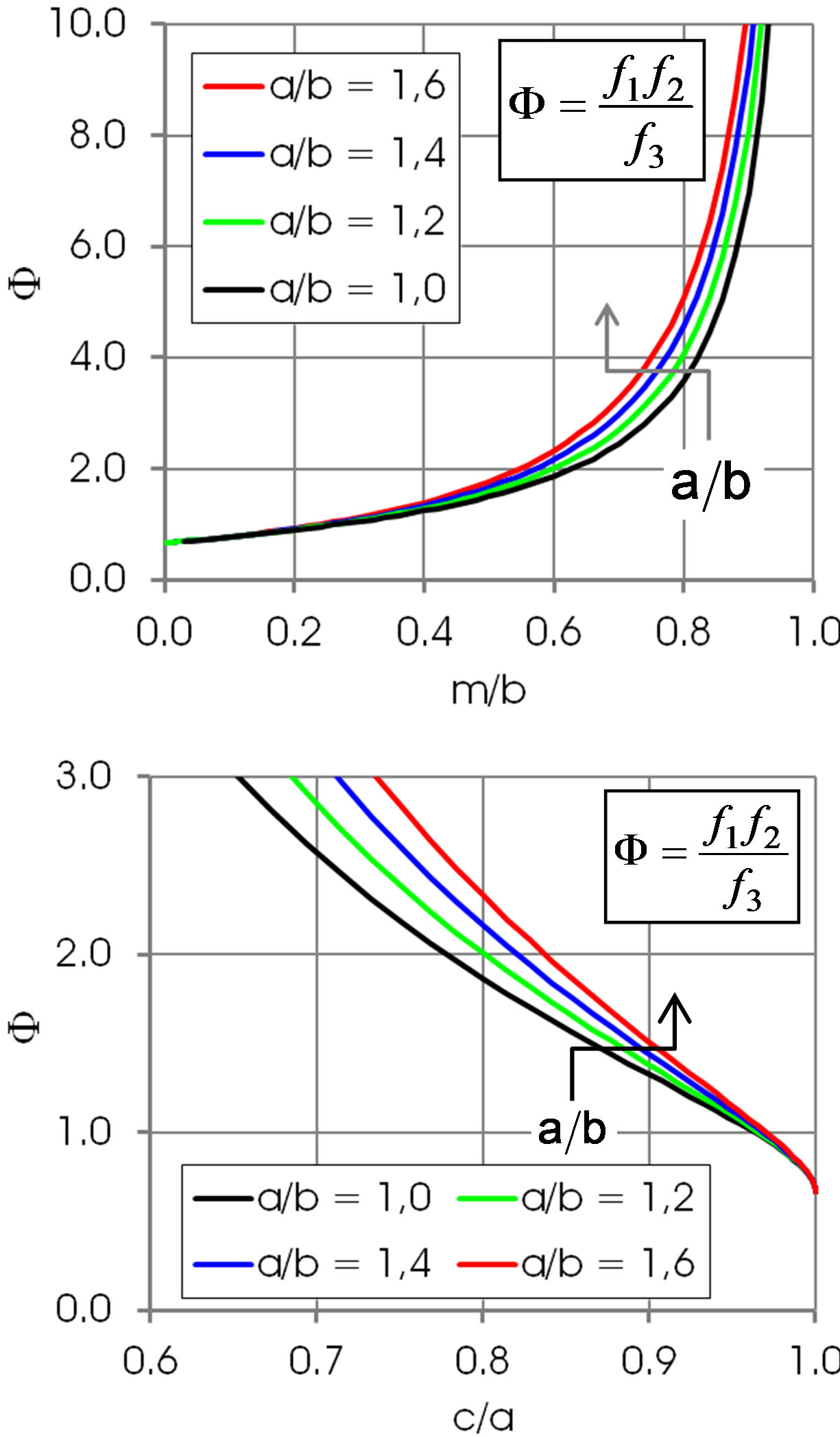
Figure 5. Shape function F in dependence of m/b and c/a. Arrows: increasing a/b. The Bond number B0 corresponding to the values a/b is 0, 0.13, 0.27 and 0.41, respectively.
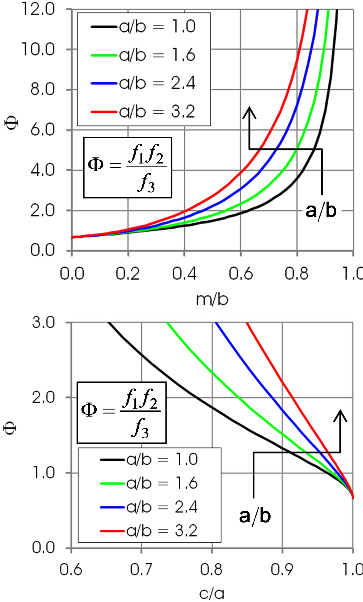
Figure 6. Shape function F in dependence of m/b and c/a. Arrows: increasing a/b. The Bond number B0 corresponding to the values a/b is 0, 0.41, 1.0 and 1.6, respectively.
ness  at larger B0. Figure 7 illustrates the dimensionless film thickens at the instance of the film rupture, Equation (19). The curve is similar to that in Figure 3.
The tensile strength of the liquid à in the expression for the film thickness  reflects implicitly the liquid structure and its molecular dynamics and depends on the system state, particularly on temperature. In addition the quantity à depends also on the purity and constitution of the liquid in case of mixtures. Theoretical values could be obtained from equations of state e.g. van der Waals equation at
 . Its determination by experiments is complex and several parameters may affect the results. For instance, in classical experiments, where solid walls are involved, the interaction of liquid molecules with the walls plays an important role; if the interaction is weak, the liquid is expected to rupture on the wall surface and not in the bulk. With free liquid surfaces, surface active substances could lower the tensile stretch. This may partly explain the scattering of the experimental results. Skripov [9] reports data for à in the rage 200 bar to 300 bar; while Williams and Williams [11] report data as low as 10 bar, see also [3,12]. The value
  and the data from the experiments of Oldenziel et al. [7] are adopted for illustration:
 ,
, ,
,  ,
,
 . With these data one obtains:
 ,
, 
Equation (16) gives the thickness of the film at instant of rupture: .
.
A comparison of the model result with experiments is almost impossible, because relevant experimental results are very rare in literature. As far as the author is aware, only the results reported by Burrill and Woods [1] are directly applicable. They studied the thin liquid film of water trapped between a rising oil drop and the bulk oil/water interface, including the film rupture. Measurements gave the film thickness at rupture in the range 300 Å to 500 Å (30 nm to 50 nm). This is of the same order of magnitude as the above model result (26 nm).
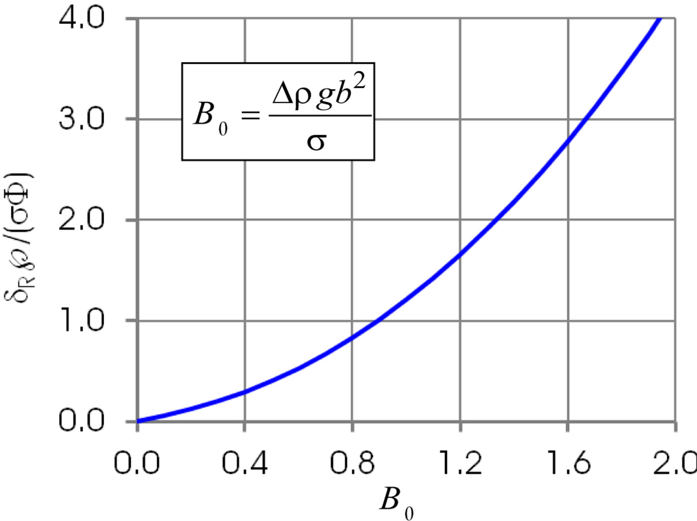
Figure 7. Dimensionless film thickness at rupture.
4. Conclusion
The shape of a droplet exposed to gravity and interacting with a liquid-liquid interface is approximated by ellipsoid generated by revolution of an ellipse around its minor (vertical) axis. The geometrical parameters of the ellipse are obtained from the static equilibrium requirements. These requirements have delivered an equation for the rupture of the interfacial film. The film rupture is expected to occur when the Archimedes force of the droplet exceeds the molecular interaction in the film expressed in terms of the tensile liquid strength. Adopting some data from experiments by Oldenziel et al. [8] the thickness of the film at the rupture amounts to 26 nm. Burrill and Woods [1] report experimental data in the range of 30 nm to 50 nm. Although the theoretical order of magnitude appears to be realistic, the main uncertainty in the film thickness at rupture is rooted in the inaccuracy of the tensile strength of liquid.
5. Acknowledgements
Professor D. R. Woods, Department of Chemical Engineering, McMaster University, Hamilton Ontario, Canada, has kindly provided some details on his experiments performed four decades ago (Ref. [1]).
REFERENCES
- K. A Burrill and D. R. Woods, “Film Shapes for Deformable Drops at Liquid-Liquid Interfaces. II. The Mechanisms of Film Drainage,” Journal of Colloid and Interface Science, Vol. 42, No. 1, 1973, pp. 15-34. doi:10.1016/0021-9797(73)90004-0
- R. Davis, J. Schonberg and J. Rallison, “The Lubrication Force between Two Viscous Drops,” Physics of Fluids A, Vol. 1, No. 4, 1989, pp. 77-81.
- A. K. Chesters, “The Modelling of Coalescence in FluidLiquid Dispersions: A Review of Current Understanding,” Transactions of the Institution of Chemical Engineers Part A, Vol. 69, No. 4, 1991, pp. 259-270.
- E. Klaseboer, J. Chevaillier, C. Gourdon and O. Masbernat, “Film Drainage between Colliding Drops at Constant Approach Velocity: Experiments and Modeling,” Journal of Colloid and Interface Science, Vol. 229, No. 1, 2000, pp. 274-285.
- I. B. Bazhlekov, A. K. Chesters and F. N. van de Vosse, “The Effect of the Dispersed to Continuous-Phase Viscosity Ratio on Film Drainage between Interacting Drops,” International Journal of Multiphase Flow, Vol. 26, No. 1, 2000, pp. 445-466.
- F. E. Massoth, W. E. Hensel Jr. and W. W. Harlowe Jr., “Basic Studies of Encapsulation Process. Correlation of Capsule Size,” Industrial & Engineering Chemistry Process Design and Development, Vol. 4, No. 1, 1965, pp. 6-13. doi:10.1021/i260013a003
- M. Abkarian, E. Loiseau and G. Massiera, “Continuous Droplet Interface Crossing Encapsulation (cDICE) for High Throughput Monodisperse Vesicle Design,” Soft Matter, Vol. 7, 2011, pp. 4610-4614.
- G. Oldenziel, R. Delfos and J. Westerweel, “Measurements of Liquid Film Thickness for a Droplet at a TwoFluid Interface,” Physics of Fluids, Vol. 24, No. 2, 2012, Article ID: 022106. doi:10.1063/1.3684706
- D. Y. C. Chan, E. Klaseboer and R. Manica, “Film Drainage and Coalescence between Deformable Drops and Bubbles,” Soft Matter, Vol. 7, No. 6, 2011, pp. 2235-2264. doi:10.1039/c0sm00812e
- V. P. Skripov, “Metastable Liquids,” J. Wiley, New York and Toronto, 1974.
- P. R. Williams and R. L. Williams, “On Anomalously Low Values of the Tensile Strength of Water,” Proceedings of the Royal Society of London A, Vol. 456, No. 1998, 2000, pp. 1321-1332. doi:10.1098/rspa.2000.0564
- M. S. Barrow, W. R. Bowen, N. Hilal, A. Al-Hussany, P. R. Williams, R. L. Williams and C. J. Wright, “A Study of the Tensile Properties of Liquids in Confined Spaces Using an Atomic Force Microscope,” Proceedings of the Royal Society of London A, Vol. 459, No. 2039, 2003, pp. 2885-2908. doi:10.1098/rspa.2003.1128
- A. R. Imre, H. J. Maris and P. R. Williams, “Liquids under Negative Pressure,” Kluwer, Dordrecht, 2002.
Nomenclature
a,b —main axes of ellipse;
c—parameter, Figure 1;
B0—Bond number;
F—force;
g—acceleration due to gravity;
m—parameter, Figure 1;
p—pressure;
×tensile strength of liquid;
R—radius;
t—parameter;
V—volume;
F—shape function;
r—density, ∆r density difference;
s—surface tension;
k—curvature.
Indices AE—Archimedes force ellipse;
AS—Archimedes force sphere;
N—direction of normal;
R—rupture;
T—direction of tangent.