New Journal of Glass and Ceramics
Vol.2 No.3(2012), Article ID:21445,11 pages DOI:10.4236/njgc.2012.23016
Thermal Analysis and Immobilisation of Spent Ion Exchange Resin in Borosilicate Glass
![]()
School of Mechanical, Aerospace and Civil Engineering, The University of Manchester, Manchester, UK.
Email: *nasirhamodi@yahoo.co.uk
Received April 4th, 2012; revised May 25th, 2012; accepted June 15th, 2012
Keywords: Absorption Processes; Borosilicate Glass; Immobilization; Ion Exchange Resin; Radiation Damage
ABSTRACT
The underground disposal of waste arising from the nuclear industry needs constant evaluation in order to improve upon it through minimizing the volume and cost by reducing the amount of glass used without compromising the safety of any leakage from the radioactive waste form. The immobilization of the spent resin (NRW-40) in borosilicate glass was investigated to meet the acceptance criteria for disposal of nuclear waste. The organic mixed bed resin in granular form was used as a waste target. The analysis of surrogate resin doped with radioactive and non-radioactive cesium (Cs) and cobalt (Co) was carried out to investigate their thermal and chemical properties and their compatibility with an alkaline borosilicate glass. The thermal analysis indicates that the structural damage caused by 1 mSv gamma radiation to the radioactive resin has altered its properties in comparison with the non-radioactive resin, same amount of cesium (8.88 wt%) and cobalt (1.88 wt%) were used in both resins. The immobilization of residue shows that the excess sulfur in the residue caused phase crystallization in the final glass matrix. It was found that the volatilization of Cs-137 and Co-60 from the successful radioactive resin-glass matrix (HG-3-IER-500) were more than that in the non-radioactive resin-glass matrix (HG-3-IEX-500). The study demonstrates comprehensive experimental and analytical works and shows that it is possible to minimise the volume of the waste while keeping the required safety levels, however further research needs to be carried out in this area.
1. Introduction
In the nuclear industry there are a number of water waste streams that require chemically controlled treatments and/or the removal of the radioactive contaminants. These chemical treatments may be used for the reactor’s primary coolants; the cleanup of spent fuel pools; or for the liquid radioactive waste management systems. Spent ion exchanges are considered to be a problematic type of waste, which in many cases require a special approach to reduce their volume (via thermal treatment) and reduce their carbon and sulfur content [1].
A common treatment method for aqueous radioactive waste streams is the use of ion exchange, which is a well-developed technique that has been employed for many years in both the nuclear and chemical industries. The regeneration process of the spent resin using acid leaching to remove the radionuclides, is uneconomical in comparison to purchasing fresh resin. The regeneration requires the use of shielding and hydraulic separation equipment to separate the cationic from anionic beads of the resin [1]. Moreover, the spent resins are accumulating at an increasing rate at nuclear industry silos.
Nowadays, there are 92 boiling water reactors (BWR), 44 pressure heavy water reactors (PHWR) and 264 pressurized water reactors (PWR) operating around the world [2]. According to study conducted by the International Atomic Energy Agency (IAEA), the maximum IEX generations are: 7, 7 and 20 m3/y for typical PHWR, PWR and BWR respectively [3]. Therefore, using the data given in Table 1, the total spent resin generated by world operating reactors is calculated to be 3996 m3/y. Another study in Russia mentioned that a nuclear power reactor of 1000 MW generate annual volume of spent IEX of more
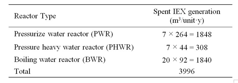
Table 1. Spent organic ion exchange resin generation by all world reactors.
than (40 m3/y) [4]. These quantities are considered to be a potential hazard to human health and the environment when it enters to the earth’s biosphere. According to reference [3] “unit” is specified as a typical nuclear plant reactor.
The focus of the previous studies was mainly to observe the influence of the doped ions in the resin on its degradation process or its residue content, followed by the characterization of the residue and the major gases evolved [5]; however, few studies such as the present one, were considered the elimination of the carbon and sulfur from the resin, or given significant consideration to the volatilization of radionuclides during heat treatment. Many studies did not consider a thermal analysis of the resin as an option to minimise the volume of the final waste except studies focused mainly with the influence of volatilization of cesium and cobalt from residue during vitrification or the advantage of the weight reduction or the impact of sulfur and carbon in the residue [6]. None of these studies dealt with the corrosives of sulfur arising from IEX immobilisation in glass [7].
In this study, ion-exchange resins is polymerized polystyrene in form of divinyl benzene (DVB) were thermally treated to different temperature in order to investigate the ability of glass matrix to integrate the resulting ash.
1.1. Sulfur Content of IEX
DVB ion exchangers are considered to be rich in carbon (49.9 wt%) and in sulfur (15.5 wt%), which restricts the waste loading in the glass matrix [8]. An organic resin stored in an aqueous phase requires thermal treatment to de-moisturize the matrix and reduce the carbon and sulfur content. High carbon content causes high Redox state of the glass, which may cause a blockage in the nozzle of the melter during vitrification, erosion of the refractory material of the melter, or difficulties in controlling its temperature [9]. High sulfur content in the glass reduces the number of bridging oxygen (n) in the structural unit of silica (Qn) and produces sodium sulfate (Na2SO4) as a covering layer on the molten glass [10]. Sodium sulfate is a good heat conductor, which causes difficulties in controlling the temperature of the melter; its good water solubility also makes the final glass less chemically durable. Additionally, it attracts radionuclides (e.g. Cs-137, Co-60 and Sr-90) to dissolve in its matrix [11]. The factors stated above make the glass matrix unacceptable for long term disposal.
The word “clean resin” refers to a resin free from any contaminants; its thermal properties were used a as reference to both the surrogate and radioactive resins. Vitrification is a well established and studied technology used in many commercial applications. It can produce high waste loading by using a suitable glass composition and achieve large reductions in waste volume. The hazard of long-term storage and the cost of disposal will increase with time if the resin cannot be regenerated or safely vitrified and disposed [12].
1.2. Risks of IEX Storage
The storage of spent resins in water and wet media poses a major challenge in nuclear waste management. In the case of wet media storage, the generation of hydrogen gas from spent ion exchange resins is a fairly well understood phenomenon and is based upon the radiolysis decomposition of water by alpha, beta and gamma radiation. Water decomposition results in the formation of hydrogen gas and hydrogen peroxide. The potential hazard, therefore, exists from the buildup of flammable hydrogen concentrations (4 vol% H2) in air, if the facility is not properly ventilated. The experimental G values of the hydrogen gas evolved from other spent resin slurry (Argentine resin samples) were in the range of 0.3 to 0.8 molecules/100 eV radiation exposure. There are other potential hazards relating to the isotopes migrating from the stored resin to the ground water in the case of a tank leakage. All these identified hazards must be isolated, reduced, controlled and eliminated throughout safe disposal of the spent resin [6].
Several attempts have been made by British Nuclear Group (BNG) to encapsulate the spent resin in a cement matrix; however, results showed that the immobilisation of 30 wt% of resin in pure Ordinary Portland Cement (OPC) gave initially a satisfactory waste form, but later on this matrix crumbled into powder over a period of only a few weeks [13]. The aim of this study is to achieve a amorphous final waste form posses low crystalline inclusions and high retention of cesium and cobalt.
2. Experimental Work
The experimental procedure was developed in the laboratory to prepare a surrogate and radioactive resins doped with equal amount of Cs (8.8 wt%) and Co (1.88 wt%) and both resins were thermally treated at various temperatures 150˚C, 300˚C, 450˚C, 650˚C and 1000˚C. The resulting residues were analysed using Thermal Gravimetric Analysis (TGA), Differential Thermal Analysis (DTA) and Carbon-Hydrogen-Nitrogen-Sulfur (CHNS) Analysis. Resulting residues were mixed independently with a fixed amount of alkaline borosilicate glass powders (38.5 wt% waste loading) and were melted at 1200˚C in a muffle furnace and then analysed using X-ray diffraction (XRD), X-ray fluorescence and Scanning Electron Microscopy (SEM).
2.1. Samples Preparation
The average diameters of the resin beads were 0.55 mm and the nominal density was 1.2 and 1.06 g/cm3 for cationic and anionic resins, respectively. The chemically bound water content was 50 wt% - 55 wt% and 48 wt% - 54 wt% for cationic and anionic resins respectively. The major radioactivity in the spent resin used in the nuclear facilities originate from cobalt (Co-58 and Co-60) and cesium (Cs-134 and Cs-137); these contributions accounted for 90% of the radioactivity measured in the cationic ion-exchange resins involved in the PWR operation. The measured concentrations of these elements in the spent resins are given below [7]:
1) 60Co: 36.7% equivalent to 1.5 × 10⁻⁴ mol/m3;
2) 58Co: 31.9% equivalent to 4.6 × 10⁻⁵ mol/m3;
3) 137Cs: 11.75% equivalent to 2.7 × 10⁻⁴ mol/m3;
4) 134Cs: 7.07% equivalent to 1.1 × 10⁻⁵ mol/m3.
These concentrations are too small to be detected during the thermal treatment and vitrification, therefore both resins were doped with higher concentrations (spiking) of the Cs and Co in order to track their mobility later. The surrogate and radioactive resins were doped with 8.88 wt% of Cs (0.65 mmol/g) and 1.88 wt% of Co (0.32 mmol/g). The doping process showed in Figure 1 shows that the resin absorbed the Cs and Co ions (violet color) from the de-ionized water.
After 24 hours, the solution was filtered through a filter paper fitted into a funnel and then the precipitant was placed in an alumina crucible and heated in a muffle furnace at various temperatures (150˚C, 300˚C, 450˚C, 650˚C, 1000˚C, 1100˚C and 1200˚C) in order to assess the thermal degradation at those temperatures and to estimate the C, S, Co and Cs content in the residues. Similar doping concen-
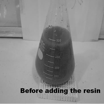
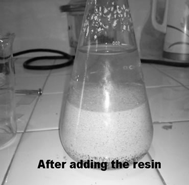
Figure 1. Photo shows ion exchanging before and after adding the clean resin to the solution of cesium and cobalt.
tration of Co and Cs were used in Zeolite resin in a previous study and it was estimated that the final concentrations of both Cs and Co should be in the range of 1.17 - 2.84 mmol/g resin [14] or 0.268 mmole/g resin [15]. In the present work, a total doping concentration of 0.97 mmol/g was used. The residues were analysed using mass spectroscopy to determine the Cs and Co concentrations, listed in Table 2.
2.2. Preparation of Alkaline Borosilicate Glass (HG-3)
Hard glass (HG-3) was developed to obtain a glass with a low melting temperature and its initial and final compositions are listed in Table 3. The final compositions of HG-3 glass were analysed using X-ray fluorescence (XRF-Panalytical XIROS, PW-4400124, Netherlands). The arising concentration of the alumina in the final glass was predicted due to the contamination of the glass from alumina crucible. The increasing silica and alumina concentrations caused a decrease of the rest precursors. Analysis of the percentage linear coefficient (PLC) of HG-3 glass using dilatometer (Netzsch DIL, 402C, Germany) determines the glass transition temperature (Tg) with error deviation of 7˚C (error 3% according to Netzsch Dilatometer) as shown in Figure 2. According to a previous study, the melting temperature TL was estimated using the Kauzmann rule equation and approximated using the average value of both glass transition temperatures [16].
 (1)
(1)
The immobilisation of the residues with the HG-3 powder is initiated by matching the grain size of both particles
Table 2. The variation in masses in g/100g resin with temperature.
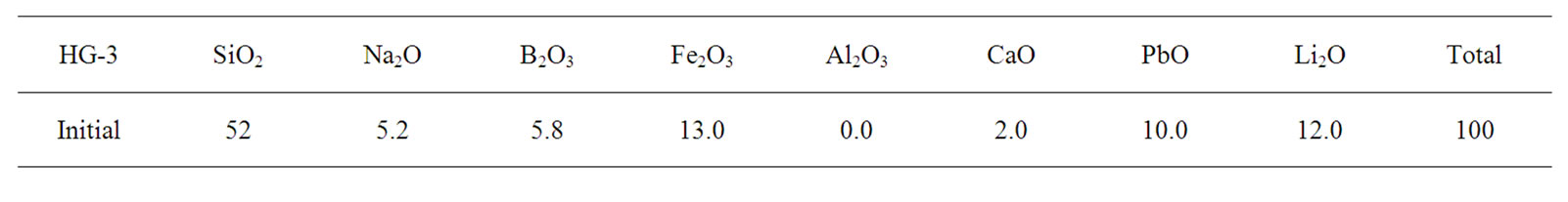
Table 3. Initial and final HG-3 glass composition.
in order to obtain a homogenous mixture. It is difficult to achieve equilibrium during glass melting without the use of a platinum stirrer or purging the air in the melter plenum [17]. Therefore, HG-3 glass was crushed and sieved to a 600 mm particle size, so that it corresponded to the particle size of the thermally treated residues. Using a portable dosimeter, the radioactive resin, when treated at 150˚C (IER-150), was estimated as having a radioactivity of 8.41 µSv/hr (see Figure 3).
It is important to note that the radiation dose rate (8.4 1 mSv/hr) corresponds to a radiation exposure of 1 mSv to one gram of IER-150 kept for 1000 hours (41 days) in its container.
The experimental procedure comprised two Batches:
First Batch: In this part, the residues treated at 150˚C were mixed with a fixed amount of borosilicate powder (fixed waste loading 38.5 wt%) in alumina and platinum crucibles. Three resins were used: clean resin, nonradioactive resin (IEX) and radioactive resin (IER); each was mixed with HG-3 glass powder (10 g of resin with 16 g glass). The initial concentrations (metal basis) of sulfur, carbon, caesium and cobalt in the resins were estimated using XRF analysis and are listed in Table 4. The crucibles were heated in a muffle furnace at 1050˚C (5˚C/min) and then quenched at room temperature.
Initially it was expected that the sulfur and carbon in the resin would decompose into carbon and sulfur (mono) dioxides during the glass melting. However, it was observed that the colour of the glass powder had changed from red (colour of Fe2O3) to dark gray (colour of C and S) during melting. This change occurred at above 500˚C can be seen in Figure 4, comparing that with Figure 3, it is obvious that the glass had absorbed some of the C and the S. Part of the Cs and Co were volatilized as the dose rate decreased from 8.41 to 8.18 mSv/hr.
Second Batch: In this part, the residues treated at 500˚C were mixed independently with a fixed amount of borosilicate powder (fixed waste loading 38.5 wt%) in alumina and platinum crucibles. The three types of resins were clean resin, non-radioactive resin (IEX) and radioactive resin (IER), and these were mixed independently with HG-3 glass powder (10 g of resin with 16 g glass). Figure 5 shows the three residues during the glass melting procedure.
The initial concentrations (metal basis) of Cs and Co in the resins treated at 500˚C were estimated using XRF, these concentrations were increased due to the weight reduction of the resins during the thermal treatment. The weight of S, C, Co and Cs concentrations are listed in Table 5. The final glass matrix appeared to have no foam or immiscible layer formation on the top of the glass as seen in Figure 5.
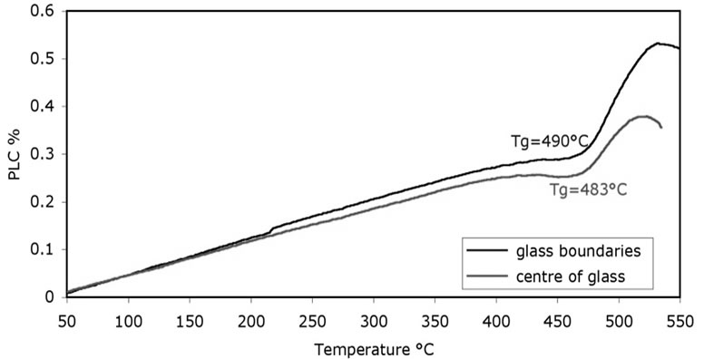
Figure 2. Percentage linear coefficient of HG-3 shows differences in Tg due to the dilatometer error.
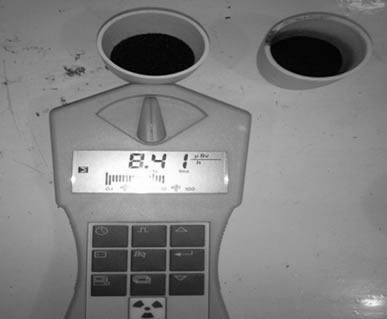

Figure 3. Photos showing IER-500 residue before and after mixing with HG-3 glass.
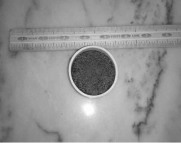
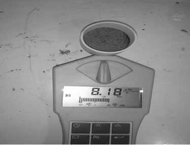
Figure 4. Photos show the mixture of HG-3 glass with IER treated at 150˚C.
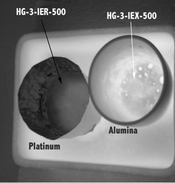
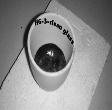
Figure 5. Photos show all glasses resulted from the second batch.

Table 4. Initial concentrations (wt%) of S, C, Cs and Co in the resin treated at 150˚C.

Table 5. Masses in (g/100g resin) of S, C, Cs and Co in resin treated at 500˚C.
3. Results
3.1. TGA and DTA
The weight reduction in the surrogate resin treated at 150˚C (IEX-150) and 300˚C (IEX-300) were analysed for comparison with the radioactive (IER) and the clean resin treated at the same temperatures (Figure 6). DTA graphs, in Figure 7, show the thermal behavior of IEX, IER and clean resins. This allows for the definition of 5 characteristic degradation regions with respect to the treatment temperature:
1) The zone W (25˚C - 150˚C) represents the evaporation of water from the resin. All the resin types (clean, IER, IEX-150 and IEX-300) have shown very little moisture content because they were already preheated to above 100˚C. The TG graph is very similar to the indion-223 and indion-225 thermal treatments, which were reported in [18];
2) The zone S (150˚C - 490˚C) represents the decomposition of S containing compounds into SO and SO2 gases. At this intermediate temperature range, the degradation of the functional group (SO3-H+) attached to the benzene group corresponds to the first peak labeled “a” and the decomposition of sulfonate group between the phenol rings to the second peak labelled as “b” in Figure 7. Similar results were reported in [19];
3) The zone C (490˚C - 650˚C) represents the decomposition of hydro-carbon matrix into CO and CO2 gases labelled as “c” in Figure 7. In the case of IER resins, it appears that the decomposition of C occurred at around 490˚C labelled as “c” and an additional decomposition at around 650˚C labelled as “c1”, which might give us an idea of why the mass loss in IER was more than in the other resins [19];
4) In the zone O (650˚C - 950˚C), the observed weight increase might be due to oxidation of the doped Cs and Co oxides in the resin to higher oxidizing valence such as Cs11O3, Cs4O and Cs7O, and Co2O3 and Co3O4 respectively. The oxidation zone may result in oxygen-rich compounds, which help in the reduction of the Redox state of the glass during vitrification later, adding to the quality of the final glass [5];
5) The zone Vs (1050˚C - 1200˚C) represents the volatilization of the Cs and Co from the IEX-150 and IEX-300 resins. The weight loss of the resins at 1050˚C and the decreasing concentrations of Cs and Co at the same temperature (Table 2) can be considered as evidence of the reduction of the concentration [20];
6) The zone Vr (950˚C - 1200˚C) represents volatilization of the radioactive oxides of Cs and Co from the IER resin [20].
Although the IER resin was loaded with same amount of Co and Cs, the residue of IER was mostly lower than residue of the rest resins over the entire temperature range (25˚C to 1200˚C), which was not expected. The rapid degradation and decomposition of the IER residue into CO2 and SO2 gases may be due to the impact of the radiation, which may have broken the C-H and S-C bonds. This was not observed in the other resins.
There was a minor difference between the TGA wt% loss results and the manually measured weight of the residues after treatments at various temperatures. Small errors (0.5 to 1 wt%) may be due to the difference in the amount of the sample used in the TGA analyzer (8 - 10 mg) and the manual procedure (8 - 10 g).
After various heat treatments, the resulting residues were crushed and sieved into powder to determine S, C and N2 contents using CHNS analysis.
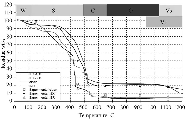
Figure 6. TGA graphs showing the wt% loss of the residue at various temperatures.
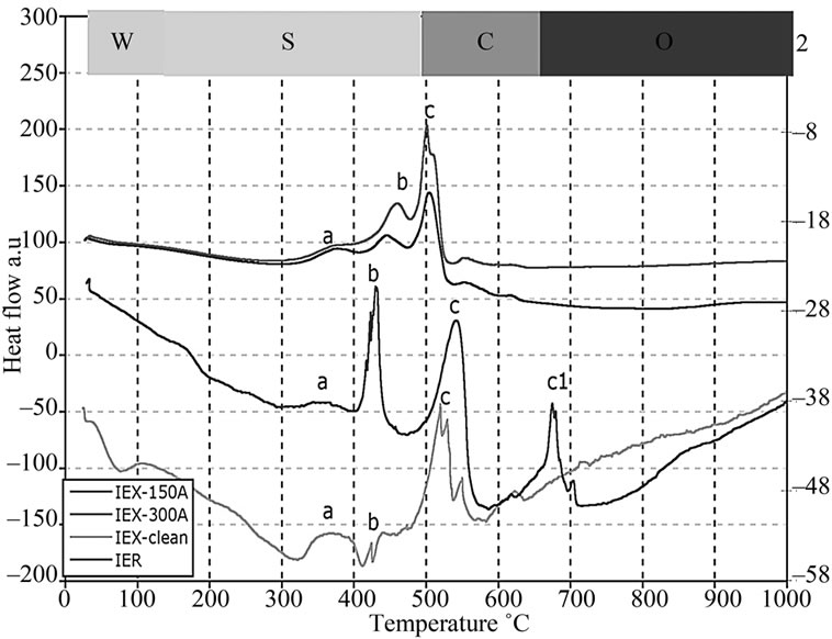
Figure 7. DTA plots showing heat absorption/emission at various temperatures.
3.2. Carbon-Hydrogen-Nitrogen-Sulfur (CHNS)
Cobalt and cesium sulfate are common products in both the residues of the IEX and IER resins. Cs2SO4 is white salt (Figure 8A) resulting from the reaction of sulfur in the functional group with the doped cesium in the resin, whilst cobalt sulfate (CoSO4) is blue coloured salt (Figure 8B). It should be noted that sulfate has a very low solubility in silicate melts (<0.6 mol%) and during a plant scale vitrification of sulfate bearing waste, an immiscible sulfate layer is formed. This comprises a water-soluble phase and a phase enriched with 137Cs and 60Co radionuclides that float above the borosilicate melt [21]. This immiscible layer prevents an easy release of the reaction gases from the melter leading to froth formation. Furthermore, the sulfate layer, being a good electricity and heat conductor, reduces the efficiency of the vitrification process [22].
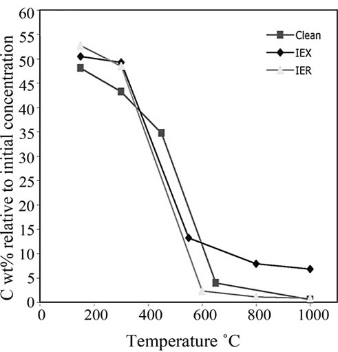
The residues treated at 150˚C, 300˚C, 650˚C, 800˚C and 1000˚C were analysed using CHNS. The data were plotted versus the treatment temperatures shown in Figure 9. The critical decomposition temperatures of C, S and N2 can be observed. These critical temperatures might provide an idea about the optimum treatment temperature of the resin. At these temperatures, S and C should decompose rapidly without major volatilization of both surrogate and radioactive Cs and Co from the resin.
Figure 9(a) shows that C begins to decompose rapidly at around 550˚C to 650˚C. It was observed that the radiation damage in the IER might result in the accumulation of relatively less C in the residue than in the IEX. High C content increases the Redox state of the final glass. Surprisingly, IER had the lowest C content during its degradation and even lower than that in the clean unloaded resin.
Observations of the sulfur degradation in the clean, IEX and IER resins indicated that S began to decompose rapidly at 300˚C to 500˚C (Figure 9(b)). It was observed that, below 600˚C, S reduction rate in IEX resin was more than in the IER resin, while at temperatures >600˚C, this phenomenon was reversed. The clean resin was then analysed as a reference to compare the contents of C, S and N2 in the IER and IEX resins.
The N2 degradation (Figure 9(c)) corresponds to the decomposition of the anion part of the resin. This resin is a 60:40 mixture of cations and anions. The anion resin has an ammonia functional group ( ) that absorbs the
  and
and  anions from the water in the fuel pond [23]. All resin types were observed to decompose linearly and completed their decompositions at around 600˚C; however, the IEX resin kept more residue N2 (~3%) than the other resins at the same temperature.
4. Discussion
The final three glass matrixes (HG-3-clean, HG-3-IEX, HG-3-IER) produced from the first batch were crumbled into glass frits as shown in Figure 10. The residues were not able to enter the glass network, so they were segregated on the boundaries and the top of the glass.
Serious damage to the bottom of the platinum crucible occurred due to the chemical reaction of high corrosives
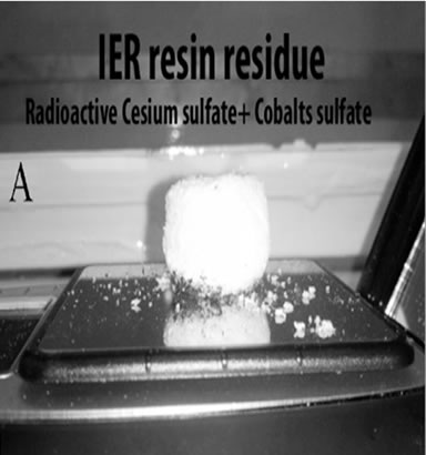

Figure 8. Photos showing cesium and cobalt sulfates after manual thermal treatment at 650˚C.
 (a)
(a)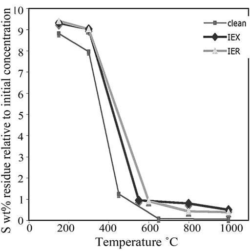 (b)
(b)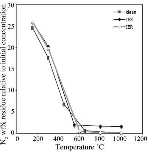 (c)
(c)
Figure 9. The plot of (a) C decomposition, (b) S decomposition and (c) N2 decomposition at various temperatures in all the investigated three types of resins.
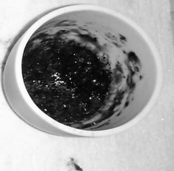
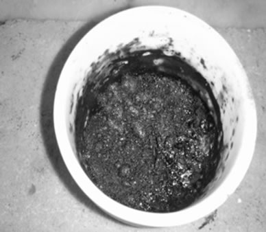
Figure 10. Photo shows the final glass matrix from the first batch bearing high content of sulfur.
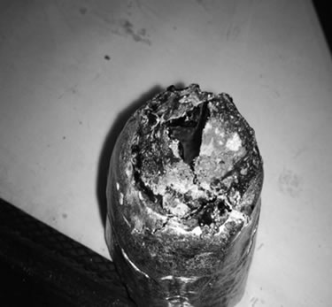
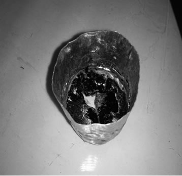
Figure 11. Photos show the damage in the upper and lower parts of a platinum crucible due to sulfur reaction under air atmosphere.
sulfur with the metal, as shown in Figure 11. The presence of sulfur in the air atmosphere created a highly corrosive environment, which then enabled the molten glass to react with a rare earth metal like Platinum at an elevated temperature.
Phase analyses of these glasses were carried out using X-ray Diffractometry (JEOL JDX 3532, Japan) with a CuKα source. XRD patterns of the glasses identified peaks over the amorphous hump labeled as “A” in Figure 12; this corresponds to cobalt cesium sulfate Cs2Co3S4, card #260368 according to library of the ICCD Data base.
A JEOL JSM5910 Scanning Electron Microscope (SEM) operating at 10 kV was used to investigate the Cs2Co3S4, within the final glass matrix. A small fine polished sample of HG3-IEX-150 was investigated; the arrows labeled the crystalline inclusion in Figure 13(A) and X-ray mapping image in Figure 13(B) shows the indentify location of Cs2Co3S4 as an inclusion in the glass matrix.
The final glass matrixes, resulting from the second batch, were inspected visually as shown in Figure 14, they were visually assessed as a homogenous and brittle glass.
Phase analyses of these glasses were carried out using X-ray Diffraction (XRD). The patterns of the glasses shown in Figure 15 were fully amorphous except Cs2O crystalline inclusions in the amorphous phase of HG-3- IEX-500 glass, which are visible at 2q of 23.1, 25.6, 29.95 and 42.7.
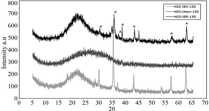
Figure 12. XRD patterns of glasses resulted from the first batch.
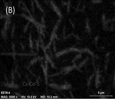
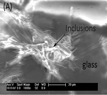
Figure 13. (A) SEM micrograph from HG3-IEX-150 glass showing the formation of a crystal inclusion; (B) X-ray mapping of HG3-IEX-150 glass shows Cs, Co and S.
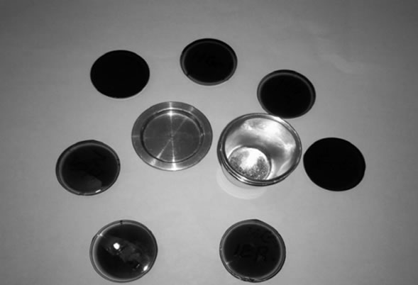
Figure 14. Photos show the glasses resulted from the second batch.
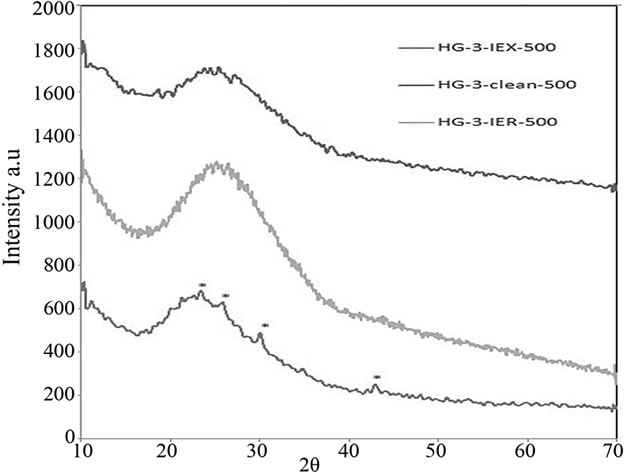
Figure 15. XRD patterns of the glasses melted in the second batch, HG-IEX-500 shows Cs2O crystalline inclusions. Cs2O peaks are labelled with an “*” in the HG-3-IEX-500 XRD pattern.
A Scanning Electron Microscope (SEM) was used to investigate the crystalline inclusions within the final glass matrix melted in the second batch. HG3-IEX-150 glass showed the formation of a minor crystal inclusion (labeled with black arrows in Figure 16(B)), while HG-3-IER-500 and HG-3-clean-500 glasses were able to integrate into their networks (labeled as black arrows in Figure 16(A) and 16(C) respectively).
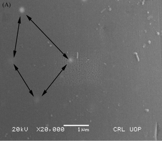
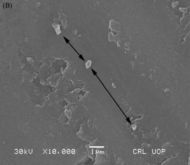
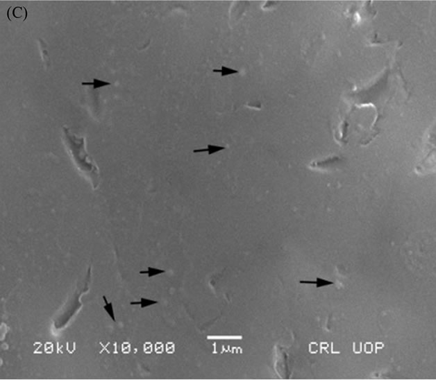
Figure 16. SEM micrograph of: (A) HG-3-clean-500; (B) HG-3-IEX-500; (C) HG-3-IER-500.
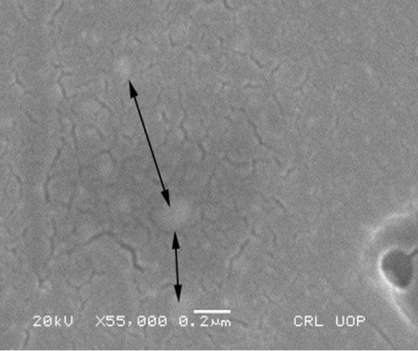
Figure 17. SEM magnified image of HG3-IER-500 glass.
The majority of the radionuclides trapped in the resin were immobilized in the glass network. Figure 17 shows a high magnification SEM image (0.2 mm) of HG-3-IER-500 glass. Light colored areas are shown by the arrows within the glass matrix that could indicate the presence of embedded crystals within the glass.
The data obtained from the XRF analysis indicate that the level of Cs-137 volatilization is less than predicted. Losses of Cs-137 and Co-60 were determined by comparing their measured final concentrations in the glass to their initial concentrations. Previous attempts by Savannah River Technology Centre (SRTC) to immobilise similar spent ion exchange resin (IRN-77, IRN-78), used in an Argentinean nuclear power plant, had shown considerable volatilisation of doped Co (11 wt%) and Cs (29 wt%) without the need for a cold cap during vitrification. The operating temperature was 1150˚C at around 30 wt% waste loading [24].
XRF analysis of the current study revealed that the losses of Cs and Co in the final glass were less than the studies achieved at SRTC; these data are listed in Table 6. Less volatilisation from the melter means less contamination to the environment despite the presence of the off-gas system and high retention of the radionuclides in the waste stream, this affect the overall efficiency of fixation of a radioactive waste in any matrix.
5. Conclusions
In the past, non-radioactive Cs and Co have been used to simulate the actual spent ion exchange resins arising from nuclear power plants. This leads to the measurement of the thermal properties of the actual resin based on surrogate resin to considerable errors due to damage caused from the radiation by breaking down the carbon-hydrogen-sulphur bonds within the radioactive resin matrix. Previous studies at SRTC, on the same type of resins using higher radioactive concentrations in a radiochemical hood, showed higher volatilisation of the Cs
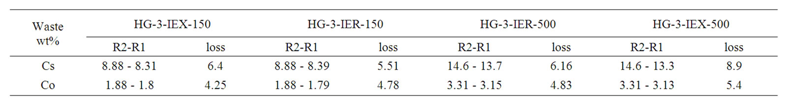
Table 6. Concentrations of initial (R1) and the final (R2) of Cs, Co in the glasses.
and Co. The major conclusions of the present study are as follows:
1) XRF analysis of the low radioactive resin (IER) revealed that part of the Cs and Co volatilisation occurred during pyrolysis before vitrification. SRTC researchers used highly radioactive doping in the resin, which consequently restricted many analyses due to the risk of radiation exposure and hazardous contamination from the resin. XRF of the initial IEX and IER solutions revealed that the loss of Cs and Co could occur during the drying process at 150˚C, and the losses in the IEX were more than in the IER solution;
2) Weight reduction and minimization of radioactive waste volume is a vital factor in water waste disposal criteria and cost. The TGA results revealed that radiation damage in the IER residue at 1000˚C (7.7 wt%) was less (~12 wt%) than IEX residue at the same temperature, despite the minor difference (3.8 wt%) in Cs doped in both the resins. TGA combined with XRF results revealed that the volatilisation of Cs and Co in IEX resin started at 1050˚C, while their volatilisation in IER resin started at 950˚C;
3) Sulphur and carbon are vital elements in thermal treatment. Different C and S decomposition profiles were observed during pyrolysis of IER and IEX at 150˚C - 1000˚C. The CHNS results demonstrated that major decomposition of sulphur occurred at 300˚C - 500˚C. Initial concentration of S was around 9.8 wt% and its final concentration was around 0.4 wt% in IER resin and 0.5 wt% in IEX resin. Carbon decomposed rapidly at 500˚C - 650˚C and its initial concentration in both the resins was around 50 wt% and its final concentration (6.9 wt%) in the IEX was around 9 times more than its final concentration (0.8 wt%) in the IER resin;
4) The N2 decomposition corresponds to the anion parts of the resin. Its decomposition occurred at 300˚C - 650˚C. Its initial concentration in both the resins was around 25 wt% and its final concentration in the IEX resin was around 1.7 wt% i.e. also around 9 times more than its final concentration (0.18 wt%) in the IER resin;
5) The final glasses resulting from the first batch were deemed unacceptable upon visual and technical inspection. Their XRD patterns showed crystalline inclusions identified as cobalt cesium sulfate (Cs2Co3S4), and their SEM images showed crystalline inclusions as well. The decomposed sulfur from the functional group of the cations in the resin was absorbed by the glass and caused damages to the final glass matrix and to the platinum crucible;
6) The final glasses resulting from the second batch were deemed partially acceptable. The XRD patterns and the SEM images showed that HG3-IEX-500 glass had minor Cs2O crystalline inclusions while both HG-3-IER- 500 and HG-3-clean-500 showed fully amorphous phases.
It can be concluded that radiation damage, or the presence of the radioactive cesium and cobalt, might be the reason behind the differences in the behavior of the resins. In this study a low volatilization of cesium (~8 wt%) and cobalt (~4 wt%) was observed. A low melting temperature of HG-3 glass allowed the resin to be burned out and the elements to be captured in the glass network before they started to volatilize from the resin. The project is underway to examine the chemical durability of the final glass matrix.
6. Acknowledgements
Thanks to the financial support of the common wealth fund and to Dr. M. I. Ojovan from the Department of Material Science, University of Sheffield/United Kingdom and Dr. Paul Chan from Management of Project at The University of Manchester/United Kingdom.
REFERENCES
- S. D. Alexandratos, “Ion Exchange Resin: A Retrospective from Industrial and Engineering Chemistry Research,” Journal of Industrial and Engineering Chemistry Research, Vol. 48, No. 1, 2009, pp. 388-394. doi:10.1021/ie801242v
- International Atomic Energy Agency, “Power Reactor Information System,” Vienna, 2010, pp. 12-22.
- International Atomic Energy Agency, “Application of Ion Exchange Processes for the Treatment of Radioactive Waste and Management of Spent Ion Exchangers,” Technical Reports Series, No. 408, 2002, pp. 2-10.
- M. Ojovan, G. Petrov and S. Dmitriev, “Incineration of Wet Ion Exchange Resin Mixed with Metal Fuel,” Proceedings of International Conference on Waste Management WM’99, Tucson, 28 February-4 March 1999, CDROM.
- R. S. Juang and T. S. Lee, “Oxidative Pyrolysis of Organic Ion Exchange Resins in the Presence of Metal Oxide Catalysts,” Journal of Hazardous Materials, Vol. 92, No. 3, 2002, pp. 301-314. doi:10.1016/S0304-3894(02)00025-0
- N. Hamodi, “Immobilisation of Spent IEX in Borosilicate Glass,” Master of Science Thesis, the University of Manchester, Manchester, 2008.
- N. D. Hutson and C. L. Crawford, “Treatment of Spent Argentine Ion Exchange Resin Using Vitrification,” Results of FY01 Testing at Savannah River Technology Centre, Aiken, 2002.
- P. Antonetti, Y. Claire, H. Massit, P. Lessart, C. Pham Van Cang and A. Perichaud, “Pyrolysis of Cobalt and Cesium Doped Cationic Ion-Exchange Resin,” Journal of Analytical and Applied Pyrolysis, Vol. 55, No. 1, 2000, pp. 89-91. doi:10.1016/S0165-2370(99)00075-3
- C. A. Cicero-Herman, D. Erich, J. Harden, K. Poole and P. Workman, “Commercial Ion Exchange Resin Vitrification in Borosilicate Glass,” Westinghouse Savannah River Company, Aiken, 1998.
- A. C. Silva and S. R. Mello-Castanho, “Vitrified Galvanic Waste Chemical Stability,” Journal of the European Ceramic Society, Vol. 27, No. 2-3, 2007, pp. 565-570. doi:10.1016/j.jeurceramsoc.2006.04.110
- D. S. Kim and P. Hrma, “Foaming in Glass Melts Produced by Sodium Sulfate Decomposition under Isothermal Conditions,” Journal of the American Ceramic Society, Vol. 74, No. 3, 2005, pp. 551-555. doi:10.1111/j.1151-2916.1991.tb04058.x
- N. Hamodi and Y. Iqbal, “Immobilisation of Ion Exchange Resin Arising from Nuclear Power Plants: An Introduction,” Journal of Pakistani Material Society, Vol. 3, No. 1, 2009.
- R. Streatfield, “Examples of Cement Formulation Development Work on Organic Ion Exchange Resins,”, Presentation 15th Meeting of the Radioactive Waste Information Network (RWIN), 31 January 2006, British Nuclear Group, University of Sheffield, Sheffield.
- R. Rodriguez-Trejo, P. Bosch and S. Bulbulian, “Combustion Treatment of Co+2 and Cs+ Exchanged Zeolites,” Journal of Nuclear Materials, Vol. 354, No. 1-3, 2006, pp. 110-122. doi:10.1016/j.jnucmat.2006.02.100
- A. Nezu, T. Morrishima and T. Watanabe, “Thermal Plasma Treatment of Waste Ion-Exchange Resins Doped with Metals,” Journal of Thin Solid Film, Vol. 435, No. 1-2, 2003, pp. 335-339.
- N. Hamodi and Y. Iqbal, “Glass Melting Techniques Used in Radioactive Waste Immobilisation,” Journal of Pakistani Material Society, Vol. 3, No. 2, 2009.
- C. M. Jantzen, D. F. Bickford, K. G. Brown, A. D. Cozzi, C. C. Herman, J. C. Marra, D. K. Peeler, J. B. Pickett, R. F. Schumacher, M. E. Smith, J. C. Whitehouse and J. R. Zamecnik, “Savannah River Site Waste Vitrification Projects Initiated throughout the United States: Disposal and Recycle Options,” Westinghouse Savannah River Company, Aiken, 2000.
- P. U. Singare, R. S. Lokhande and R. S. Madyal, “Thermal Degradation Studies of Some Strongly Acidic Cation Exchange Resins,” Open Journal of Physical Chemistry, Vol. 1, No. 2, 2011, pp. 45-54. doi:10.4236/ojpc.2011.12007
- N. Bothe, F. Doscher, J. Klein and H. Widdecke, “Thermal Stability of Sulphonated Styrene-Divinylbenzene Resins,” Journal of Polymer, Vol. 20, No. 7, 1979, pp. 850-854. doi:10.1016/0032-3861(79)90122-8
- M. A. Dubois, J. F. Dozol, C. Nicotra, J. Serose and C. Massiani, “Pyrolysis and Incineration of Cationic Ion Exchange Resins—Identification of Volatile Degradation Compounds,” Journal of Analytical Applications and Pyrolysis, Vol. 31, 1995, pp. 129-1340. doi:10.1016/0165-2370(94)00817-K
- R. K. Mishra, K. V. Sudarsan, P. Sengupta and R. K. Vatsa, “Role of Sulfate in Structural Modifications of Sodium Barium Borosilicate Glass Developed for Nuclear Waste Immobilisation,” Journal of American Ceramic Society, Vol. 91, No. 12, 2008, pp. 3903-3907.
- L. D. Pye, A. Montenero and I. Joseeph, “Properties of Glass-Form Melts,” Taylor & Francis Group Publication, London, 2005, pp. 399-401. doi:10.1201/9781420027310
- C. N. Cascaval, G. Mocanu and A. Carpov, “Characterisation of Some Acrylic Anion-Exchangers by Pyrolysis-Gas Chromatography,” Journal of Thermal Analysis, Vol. 28, No. 2, 1983, pp. 325-332. doi:10.1007/BF01983267
- N. E. Bibler, W. T. Boyce, T. L. Fellinger, S. L. Marra, R. J. O’Drisscoll and J. W. Ray, “Tc-99 and Cs-137 Volatility from the DWPF Production Melter during Vitrification of the First Macrobatch at the Savannah River Site,” Westinghouse Savannah River Company, Aiken, 2001, pp. 7-9.
NOTES
*Corresponding author.