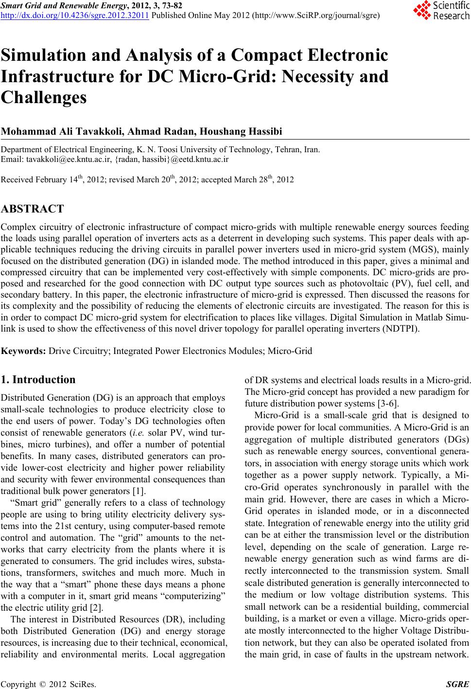
 Smart Grid and Renewable Energy, 2012, 3, 73-82 http://dx.doi.org/10.4236/sgre.2012.32011 Published Online May 2012 (http://www.SciRP.org/journal/sgre) 1 Simulation and Analysis of a Compact Electronic Infrastructur e fo r D C Mi cro -G ri d: Necessity and Challenges Mohammad Ali Tavakkoli, Ahmad Radan, Houshang Hassibi Department of Electrical Engineering, K. N. Toosi University of Technology, Tehran, Iran. Email: tavakkoli@ee.kntu.ac.ir, {radan, hassibi}@eetd.kntu.ac.ir Received February 14th, 2012; revised March 20th, 2012; accepted March 28th, 2012 ABSTRACT Complex circuitry of electronic infrastructure of compact micro-grids with multiple renewable energy sources feeding the loads using parallel operatio n of inverters acts as a deterrent in developing such systems. This paper deals with ap- plicable techniques reducing the driving circuits in parallel power inverters used in micro-grid system (MGS), mainly focused on the distributed generation (DG) in islanded mode. The method introduced in this paper, gives a minimal and compressed circuitry that can be implemented very cost-effectively with simple components. DC micro-grids are pro- posed and researched for the good connection with DC output type sources such as photovoltaic (PV), fuel cell, and secondary battery. In this paper, the electronic infrastructure of micro-grid is expressed. Then discussed the reasons for its complexity and the possibility of reducing the elements of electronic circuits are investigated. The reason for this is in order to compact DC micro-grid system for electrification to places like villages. Digital Simulation in Matlab Simu- link is used to show the effectiveness of this novel driver topology for parallel operating inverters (NDTPI). Keywords: Drive Circuitry; Integrated Power Electronics Modules; Micro-Grid 1. Introduction Distributed Generation (DG) is an approach that employs small-scale technologies to produce electricity close to the end users of power. Today’s DG technologies often consist of renewable generators (i.e. solar PV, wind tur- bines, micro turbines), and offer a number of potential benefits. In many cases, distributed generators can pro- vide lower-cost electricity and higher power reliability and security with fewer environmental consequences than traditional bulk power generators [1]. “Smart grid” generally refers to a class of technology people are using to bring utility electricity delivery sys- tems into the 21st century, using computer-based remote control and automation. The “grid” amounts to the net- works that carry electricity from the plants where it is generated to consumers. The grid includes wires, substa- tions, transformers, switches and much more. Much in the way that a “smart” phone these days means a phone with a computer in it, smart grid means “computerizing” the electric utility grid [2]. The interest in Distributed Resources (DR), including both Distributed Generation (DG) and energy storage resources, is increasing due to their technical, economical, reliability and environmental merits. Local aggregation of DR systems and electrical loads results in a Micro-grid. The Micro-grid concept has provided a new paradigm for future distribution p ow er systems [3-6]. Micro-Grid is a small-scale grid that is designed to provide power for local communities. A Micro -Grid is an aggregation of multiple distributed generators (DGs) such as renewable energy sources, conventional genera- tors, in association with energy storage units wh ich work together as a power supply network. Typically, a Mi- cro-Grid operates synchronously in parallel with the main grid. However, there are cases in which a Micro- Grid operates in islanded mode, or in a disconnected state. Integration of renewable energy into the utility g rid can be at either the transmission level or the distribution level, depending on the scale of generation. Large re- newable energy generation such as wind farms are di- rectly interconnected to the transmission system. Small scale distributed generation is generally interconnected to the medium or low voltage distribution systems. This small network can be a residential building, commercial building, is a market or even a v illage. Micro-grids oper- ate mostly interconnected to the higher Voltage Distribu- tion network, but they can also be operated isolated from the main grid, in case of faults in the upstream network. Copyright © 2012 SciRes. SGRE  Simulation and Analysis of a Compact Electronic Infrastructure for DC Micro-Grid: Necessity and Challenges 74 The flexibility of micro-grids comprises important bene- fits, but their efficient implementation poses very chal- lenging problems, as listed next [7]: The benefits Micro-grids provide to power system operation and planning need to be quantified and in- corporated into an appropriate commercial and regu- latory framework, so that a level playing field for all energy technologies can be established. In order to achieve the full benefits from the operation of Mi- cro-grids, it is important that the integration of the distributed resources into th e LV grids, and their rela- tion with the Medium Voltage (MV) network up- stream, will contribute to optimize the general opera- tion of the system. The coordinated control of a large number of distrib- uted sources with probably conflicting requirements and limited communication imposes the adoption of mostly distributed intelligence techn iqu es. The design of Micro-source Controllers enhanced with advanced frequency and voltage control capabilities and possessing ride-through capabilities is essential for the stable operation of Micro-grids, especially in islanded mode of operation. The design of smart Storage and Load Controllers able to face the stringent requirements posed by the islanded operation and especially during transition from inter- connected to islanded mode is also crucial. 2. DC Micro-Grid or AC Micro-Grid? A micro-grid can be built using AC or DC current net- work [8]. Figure 1 shows the overview of network con- nectivity to distributed generation sources [9]. Despite the fact that the AC micro-grid syste m has a benefit to utilize existing AC grid technologies, protections and standards ts application involves some problem of low efficiency i (a) (b) Figure 1. Types of micro-grid (a) DC micro-grid; (b) AC micro-grid. Copyright © 2012 SciRes. SGRE  Simulation and Analysis of a Compact Electronic Infrastructure for DC Micro-Grid: Necessity and Challenges 75 due to the number of power conversions required within the crucial current path from the main grid to the loads. One solution of this problem is the application of a DC micro-grid as an efficient method to combine high reli- ability and the possibility to reduce the losses. It can eli- minate DC/AC or AC/DC power conversion stage and thus has advantages in the stand of efficiency, cost and system size. DC micro-grid is inspired by the absence of reactive power, the possibility of the efficient integration of small-distributed generation units and the fact that, internally, all the loads operate using a DC voltage [10]. AC micro-grid imposed the inverters on both sides, gen- eration and load. Therefore, in recent years has raised the idea of using DC distribution network. DC micro-grid is suitable for home loads which are mainly of DC loads. This method eliminates the ac/dc interface. DC micro- grid, also by one or more inverters is connected to the utility grid and industrial loads (ac loads). However, some references [11] have introduced a hybrid network that, the DC link and AC link is used. The DC micro-grid has the following adva nt ages over the AC micro-grid: There is no need to consider about synchronization with the utility grid and reactive power [12]. When a blackout or voltage sag occurs in the utility grid, it does not affect dc bus voltage of dc micro-grid directly due to the stored energy of the dc capacitor and the voltage control of AC/DC converter. There- fore, DGs in DC system are not easy to trip against these disturbances. In other words, DC micro-grid al- ready has fault-ride through capability in its own [12]. No need for frequency and phase control: Because DC micro-grid, through a DC/AC converter connects to utility grid. Therefore, any change in frequency net- work does not affect the operating frequency and other ac loads of micro- grid. Number of converters used in the DC bu s is lower than the AC bus [9]. In [13] has shown that the connecting energy system combining fuel cell and solar cell us ing DC bus, inject THD less into the network. In DC micro-grid because, AC loads connected to the DC bus this opportunity exists in a condition that is generation power more than load, especially in islanded mode, some non-critical loads out of orbit and was feeding sensitive loads [14]. In [15] losses comparison between AC micro-grid and DC micro-grid. Shown that losses in DC micro-grid, 15% lower than the AC Micro-grid. In the same conditions, power transmission in DC sys- tem is higher than the AC system [16]. In DC micro-grid, DC cables can be used to reduce the investment cost [16]. In DC micro-grid voltage only affected by the active power therefore, it is simple to control [17]. Lack of electrical hazards, other advantages of using a DC bus [18]. Of course, there are some drawbacks to put dc micro- grid to practical use as follows [19]: It is needed to construct private dc distribution lines for dc mi cro -grid. The protection in dc system is more difficult than the AC system’s because there is no zero cross point of voltage in DC system. The loads adapted for dc power supply are required for high system efficiency. 3. Prerequisite Micro-Grid The smart-grid will incorporate a variety of technologies and tools, allowing the grid to work far more efficiently. The US Department of Energy has listed five fundamen- tal technologies that will drive the smart grid; these tech- nologies include [1]: Integrated communications, connecting components to open architecture for real-time information and con- trol, allowing every p art of the grid to both “talk” and “listen”. Sensing and measurement technologies, to support faster and more accurate response, such as remote monitoring. Advanced components, to apply the latest research in superconductivity, storage, power electronics and di- agnostics. Advanced control methods, to monitor essential com- ponents, enabling rapid diagnosis and precise solu- tions appropriate to any event. Improved interfaces and decision support, to amplify human decision-making, transforming grid operators and managers into visionaries when it comes to see- ing into their systems. Because this paper focuses on power electronics devices and electronic infrastructure, therefore, the more details about the third technology that is related to this subject are presented. Different distributed energy systems require various power electronics topologies for converting the generated power to the utility compatible power. The photovoltaic (PV) and fuel cell systems generate DC power which needs to be converted to single-or three-phase AC for utility connection. Additionally, an isolated DC-DC con- verter is often used before the DC-AC inverter in order to avoid bulky line frequency transformers for isolation and voltage boosts. Wind micro turbine systems generate vari- able frequency AC output which must be converted into 50 Hz AC for utility connection. The use of a back-to- back converter is the most efficient way to utilize the g en- erated power. Typically, most internal combustion (IC) engines are interconnected to the utility through a fixed- speed synchronous generator that has protective relays. A Copyright © 2012 SciRes. SGRE 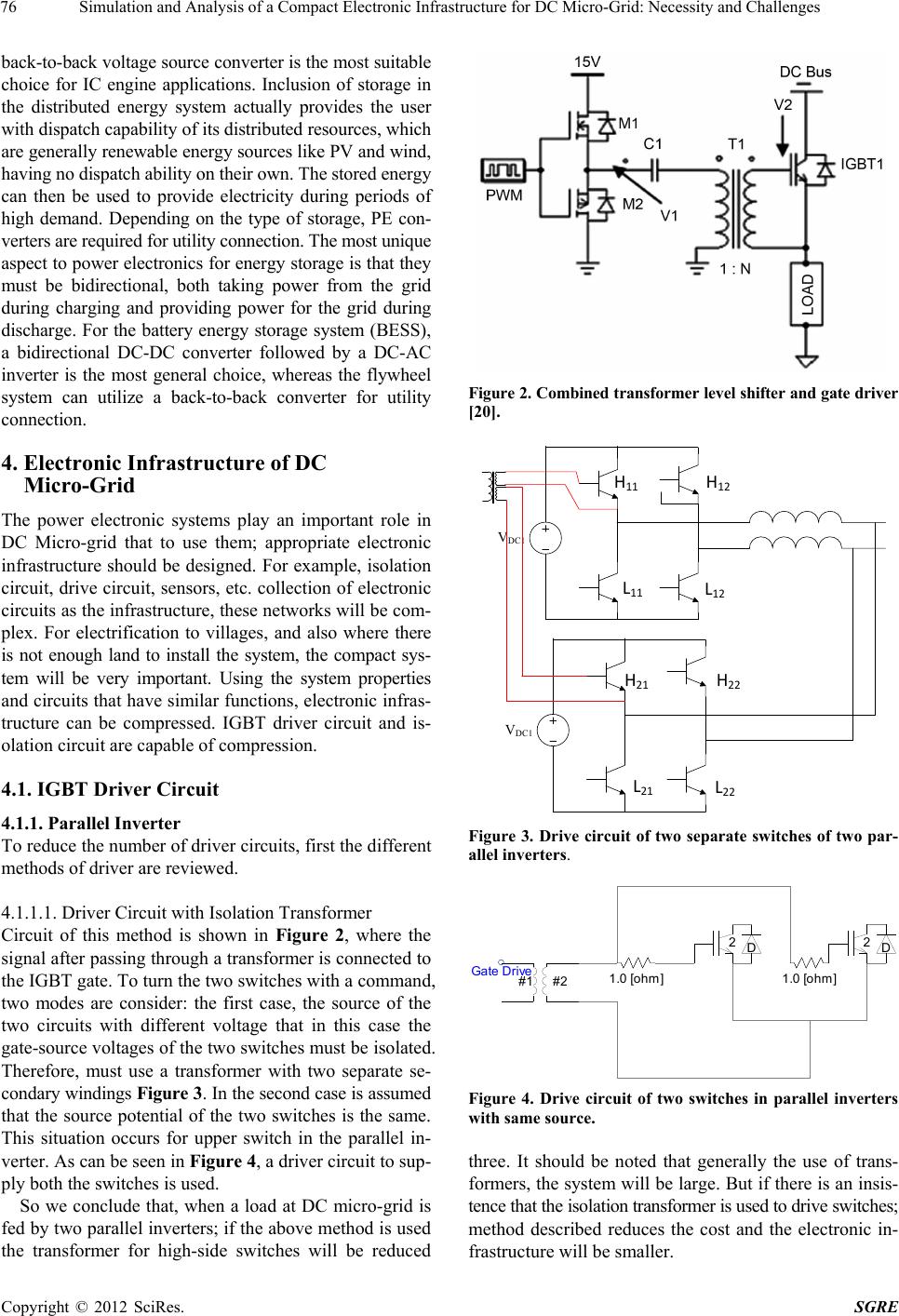 Simulation and Analysis of a Compact Electronic Infrastructure for DC Micro-Grid: Necessity and Challenges 76 back-to-back voltage source converter is the most suitable choice for IC engine applications. Inclusion of storage in the distributed energy system actually provides the user with dispatch capabilit y of its distribu ted resour ces, which are generally renewable energy sources like PV and wind , having no dispatch abi l ity on t heir own . The stored energy can then be used to provide electricity during periods of high demand. Depending on the type of storage, PE con- verters are required for utility connection. The m ost unique aspect to power electronics for energy storage is that they must be bidirectional, both taking power from the grid during charging and providing power for the grid during discharge. For the battery energy storage system (BESS), a bidirectional DC-DC converter followed by a DC-AC inverter is the most general choice, whereas the flywheel system can utilize a back-to-back converter for utility connection. 4. Electronic Infrastructure of DC Micro-Grid The power electronic systems play an important role in DC Micro-grid that to use them; appropriate electronic infrastructure should be designed. For example, isolation circuit, drive circuit, sensors, etc. collection of electronic circuits as the infrastructure, these networks will be com- plex. For electrification to villages, and also where there is not enough land to install the system, the compact sys- tem will be very important. Using the system properties and circuits that have similar functions , electronic infras- tructure can be compressed. IGBT driver circuit and is- olation circuit are capable of compression. 4.1. IGBT Driver Circuit 4.1.1. Parallel Inverter To reduce the number of driver circuits, first the different methods of driver are reviewed. 4.1.1.1 . Driver Ci rcuit with Is ol ation Transform e r Circuit of this method is shown in Figure 2, where the signal after passing through a transformer is connected to the IGBT gate. To turn the two switches with a command, two modes are consider: the first case, the source of the two circuits with different voltage that in this case the gate-source voltages of the two switches must be isolated. Therefore, must use a transformer with two separate se- condary windings Figure 3. In the second case is assumed that the source potential of the two switches is the same. This situation occurs for upper switch in the parallel in- verter. As can be seen in Figure 4, a driver circuit to sup- ply both the switches is used. So we conclude that, when a load at DC micro-grid is fed by two parallel inverters; if the above method is used the transformer for high-side switches will be reduced Figure 2. Combined transformer level shifter and gate driver [20]. VDC1 VDC1 L11 L12 H11 H12 L21 L22 H21 H22 Figure 3. Drive circuit of two separate switches of two par- allel inverters. 2D2D #1 #2 Gate Drive1.0 [ohm]1.0 [oh m] Figure 4. Drive circuit of two switches in parallel inverters with same source. three. It should be noted that generally the use of trans- formers, the system will be large. But if there is an insis- tence that the isolation transformer is used to drive switches; method described reduces the cost and the electronic in- frastructure will be smaller. Copyright © 2012 SciRes. SGRE 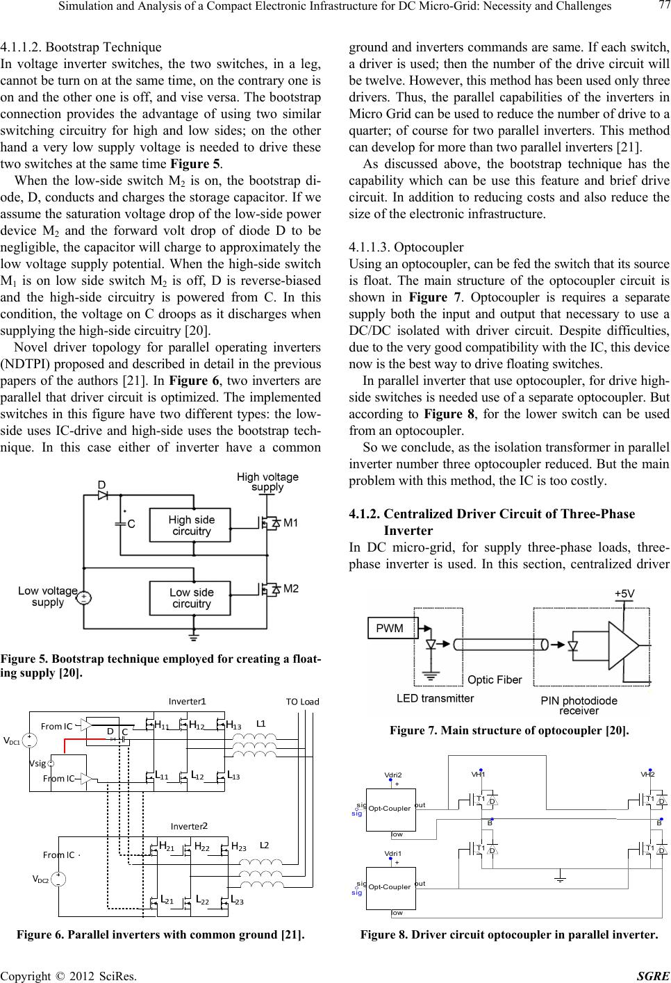 Simulation and Analysis of a Compact Electronic Infrastructure for DC Micro-Grid: Necessity and Challenges 77 4.1.1.2. Bootstrap Technique In voltage inverter switches, the two switches, in a leg, cannot be turn on at the same time, on the contrary one is on and the other one is off, and vise versa. The bootstrap connection provides the advantage of using two similar switching circuitry for high and low sides; on the other hand a very low supply voltage is needed to drive these two switches at the same time Figure 5. When the low-side switch M2 is on, the bootstrap di- ode, D, conducts and charges the storage capacitor. If we assume the saturation voltage drop of the low-side power device M2 and the forward volt drop of diode D to be negligible, the capacitor will charg e to approximately the low voltage supply potential. When the high-side switch M1 is on low side switch M2 is off, D is reverse-biased and the high-side circuitry is powered from C. In this condition, the voltage on C droops as it discharges when supplying the high-side circuitry [20 ]. Novel driver topology for parallel operating inverters (NDTPI) proposed and described in detail in the previous papers of the authors [21]. In Figure 6, two inverters are parallel that driver circuit is optimized. The implemented switches in this figure have two different types: the low- side uses IC-drive and high-side uses the bootstrap tech- nique. In this case either of inverter have a common Figure 5. Bootstrap technique employed for creating a float- ing supply [20]. Figure 6. Parallel inverters with common ground [21]. ground and inverters commands are same. If each switch, a driver is used; then the number of the drive circuit will be twelve. However, this method has been used only three drivers. Thus, the parallel capabilities of the inverters in Micro Grid can be used to reduce the number of drive to a quarter; of course for two parallel inverters. This method can develop for more than two parallel inverters [21]. As discussed above, the bootstrap technique has the capability which can be use this feature and brief drive circuit. In addition to reducing costs and also reduce the size of the electronic infrastructure. 4.1.1.3. Optocoupler Using an optocoup ler, can be fed the switch that its source is float. The main structure of the optocoupler circuit is shown in Figure 7. Optocoupler is requires a separate supply both the input and output that necessary to use a DC/DC isolated with driver circuit. Despite difficulties, due to the very good compatibility with the IC, this device now is the best way to dri ve fl oati ng swi t c hes. In parallel inverter that use optocoupler, for drive high- side switches is needed use of a separate optocoupler. But according to Figure 8, for the lower switch can be used from an optocoupl er. So we conclude, as the isolation transformer in parallel inverter number three optocoupler reduced . But the main problem with this method, the IC is too costly. 4.1.2. Centralized Driver Circuit of Three-Phase Inverter In DC micro-grid, for supply three-phase loads, three- phase inverter is used. In this section, centralized driver Figure 7. Main structure of optocoupler [20]. T1 B T1 D D T1 B T1 D D VH2VH1 + sig out low Opt-Co upler + sig out low Opt-Co upler sig sig sig + sig out low Opt-Coupler Vdri3Vdri2 Vdri1 Figure 8. Driver circuit optocoupler in parallel inverter. Copyright © 2012 SciRes. SGRE 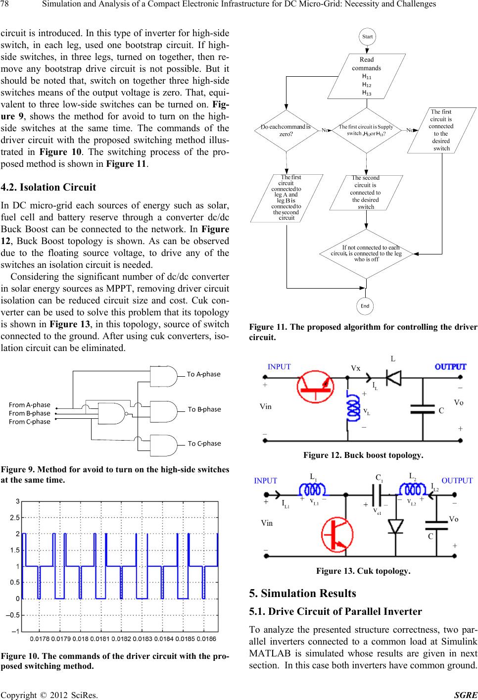 Simulation and Analysis of a Compact Electronic Infrastructure for DC Micro-Grid: Necessity and Challenges 78 circuit is introduced. In this type of inverter for high-side switch, in each leg, used one bootstrap circuit. If high- side switches, in three legs, turned on together, then re- move any bootstrap drive circuit is not possible. But it should be noted that, switch on together three high-side switches means of the output voltage is zero. That, equi- valent to three low-side switches can be turned on. Fig- ure 9, shows the method for avoid to turn on the high- side switches at the same time. The commands of the driver circuit with the proposed switching method illus- trated in Figure 10. The switching process of the pro- posed method is shown in Figure 11. 4.2. Isolation Circuit In DC micro-grid each sources of energy such as solar, fuel cell and battery reserve through a converter dc/dc Buck Boost can be connected to the network. In Figure 12, Buck Boost topology is shown. As can be observed due to the floating source voltage, to drive any of the switches an isolation circu it is needed. Considering the significant number of dc/dc converter in solar energy sources as MPPT, removing driver circuit isolation can be reduced circuit size and cost. Cuk con- verter can be used to solve this problem that its topology is shown in Figure 13, in this topology, source of switch connected to the ground. Af ter using cuk converters, iso- lation circuit can be eliminated. Figure 9. Method for avoid to turn on the high-side switches at the same time. Figure 10. The commands of the driver circuit with the pro- posed switching method. Figure 11. The proposed algorithm for controlling the driver circuit. Figure 12. Buck boost topology. Figure 13. Cuk topology. 5. Simulation Results 5.1. Drive Circuit of Parallel Inverter To analyze the presented structure correctness, two par- allel inverters connected to a common load at Simulink MATLAB is simulated whose results are given in next section. In this case both inverters have common ground. Copyright © 2012 SciRes. SGRE  Simulation and Analysis of a Compact Electronic Infrastructure for DC Micro-Grid: Necessity and Challenges 79 In part of the drive circuit, because the emphasis is on bootstrap technique then simu lation results this techniqu e will be shown that described in detail in the previous papers of the authors [21]. The power circuit for the complete inverters system is shown in Figure 6. The DC input stage of the inverters consists of a 500V DC source along with two inductors have been serried with each switch, before they are con- nected to the load, for damp out the transient current. Figure 14, presents gate source voltage of switch H11 while drive by an IC-driver separated without bootstrap method, Figures 15-19, presents conditions at which in- verters are common in ground, Figure 15, shows low- side switches gate source voltage (L21) and Figure 16, shows high-side switch gate source voltage (H11) that maximum voltage is 14 volt, the voltage drop is due to bootstrap capacitor discharge at the time of (HX) switches run up. Figure 17 shows gate source voltage (H21) and Figure 18 shows bootstrap capacitor voltage to the ground whose voltage is about 500 volt. Figure 19 is presented to con- firm inverters performance wi th suggested structure. For simplicity, in Figure 6 the d r iv er c ir cu it fo r a ph a se is shown; but similarly to the other phases of the sample used. 0.108 0.10850.109 0.10950.11 0 5 10 15 t/s Gate-s ource vol ta ges switch (H 11 ) /V Figure 14. H11 switch gate source voltage. t/s Gate-source voltages switch (L 21 ) /V 0.1080.1085 0.1090.10950.11 0 5 10 15 Figure 15. L21 switch gate source voltage. 0.108 0.10850.109 0.10950.11 -2 0 2 4 6 8 10 12 14 16 t/s Gate-s our ce v oltages switch (H 11 ) /V Figure 16. H11 switch gate source voltage. t/s G ate-sour ce volta ges sw itch (H 21 ) /V 00.02 0.040.06 0.080.10.12 0.14 0.16 0.180.2 -5 0 5 10 15 20 25 30 Figure 17. H21 gate source voltage in common ground con- dition. 0.108 0.1085 0.109 0.10950.11 0 100 200 300 400 500 600 t/s Bootstrap ca pac itor voltage /V Figure 18. Bootstrap capaci tor voltage to the ground. 00.05 0.10.15 0.2 -25 -20 -15 -10 -5 0 5 10 15 20 25 t/s Output current/A Figure 19. Parallel inverter output current. Copyright © 2012 SciRes. SGRE  Simulation and Analysis of a Compact Electronic Infrastructure for DC Micro-Grid: Necessity and Challenges 80 5.2. Isolation Circuit In Figure 20 each source such as solar, fuel cell and bat- tery reserve through a converter dc/dc Buck Boost or cuk connected to DC bus that its voltag e value con stant 48 V. Simulation results are shown in Figures 21 and 22. 5.3. Drive Circuit of Three-Phase Inverter In Figures 23 and 24, inverter output voltage and fre- quency spectrum it shows. Vol tage three- phase i nverter with the conventional bootstrap circuit is quite similar. Figures 25 and 26 show the gate-source voltage switch H11. Fig- ure 25 shows the envelope curve in any one of points; the applied voltage to the switch H11 limit is not exceeded. The peak voltage in Figure 26, a bootstrap capacitor dis- charge is visible. For the circuit is functioning correctly the bootstrap capacitors are able to supply enough energy to turn the switch. Figures 27 and 28 in the voltage across this cap- acitor are shown. Be seen, voltage across bootstrap cap- acitor at about 15 volts and the capacitor voltage ripple is 13% that is acceptable. Therefore, two circuits are well able to supply enough energy to turn switches. 6. Conclusion Electrification to home load, market, commercial building or even villages and also where there is not enough land to install the system, the compact system will be very important. One of the ideas in this regard is the u se of the Figure 20. DC micro-grid. Figure 21. DC bus voltage with Buck boost converter. Figure 22. DC bus voltage with cuk converter. Figure 23. Output voltage of three-phase inverter with the proposed switching method. Figure 24. Frequency spe ctrum w ith the pr oposed sw itching method. Copyright © 2012 SciRes. SGRE 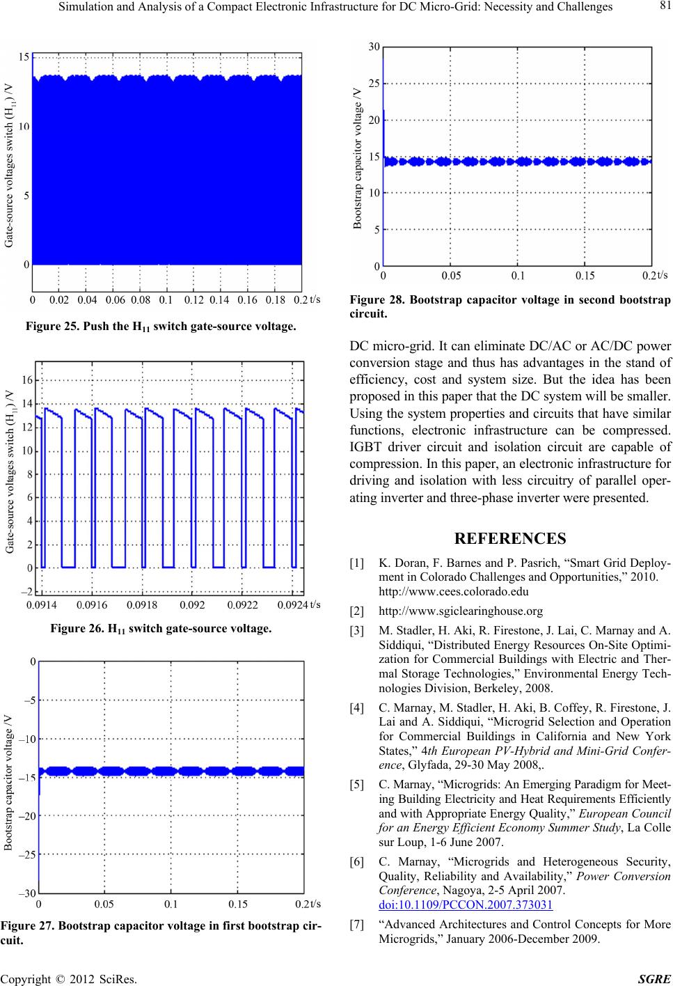 Simulation and Analysis of a Compact Electronic Infrastructure for DC Micro-Grid: Necessity and Challenges 81 Figure 25. Push the H11 switch gate-source voltage. Figure 26. H11 switch gate-source voltage. Figure 27. Bootstrap capacitor voltage in first bootstrap cir- cuit. Figure 28. Bootstrap capacitor voltage in second bootstrap circuit. DC micro-grid. It can eliminate DC/AC or AC/DC power conversion stage and thus has advantages in the stand of efficiency, cost and system size. But the idea has been proposed in this pape r that the DC syste m will be s maller. Using the system properties and circuits that have similar functions, electronic infrastructure can be compressed. IGBT driver circuit and isolation circuit are capable of compression. In this paper, an electronic infrastructure for driving and isolation with less circuitry of parallel oper- ating inverter and t h ree-p has e inverter were presented. REFERENCES [1] K. Doran, F. Barnes and P. Pasrich, “Smart Gri d Deploy- ment in Colorado Challenges and Opportunities,” 2010. http://www.cees.colorado.edu [2] http://www.sgiclearinghouse.org [3] M. Stadler, H. Aki, R. Firestone, J. Lai, C. Marnay and A. Siddiqui, “Distributed Energy Resources On-Site Optimi- zation for Commercial Buildings with Electric and Ther- mal Storage Technologies,” Environmental Energy Tech- nologies Division, Berkeley, 2008. [4] C. Marnay, M. Stadler, H. Aki, B. Coffey, R. Firestone, J. Lai and A. Siddiqui, “Microgrid Selection and Operation for Commercial Buildings in California and New York States,” 4th European PV-Hybrid and Mini-Grid Confer- ence, Glyfada, 29-30 May 2008,. [5] C. Marnay, “Microgri ds: An Eme rging Paradi gm for Meet- ing Building Electricity and Heat Requirements Efficiently and with Appropriate Energy Quality,” European Council for an Energy Efficient Economy Summer Study, La Colle sur Loup, 1-6 June 2007. [6] C. Marnay, “Microgrids and Heterogeneous Security, Quality, Reliability and Availability,” Power Conversion Conference, Nagoya, 2-5 April 2007. doi:10.1109/PCCON.2007.373031 [7] “Advanced Architectures and Control Concepts for More Microgrids,” January 2006-December 2009. Copyright © 2012 SciRes. SGRE 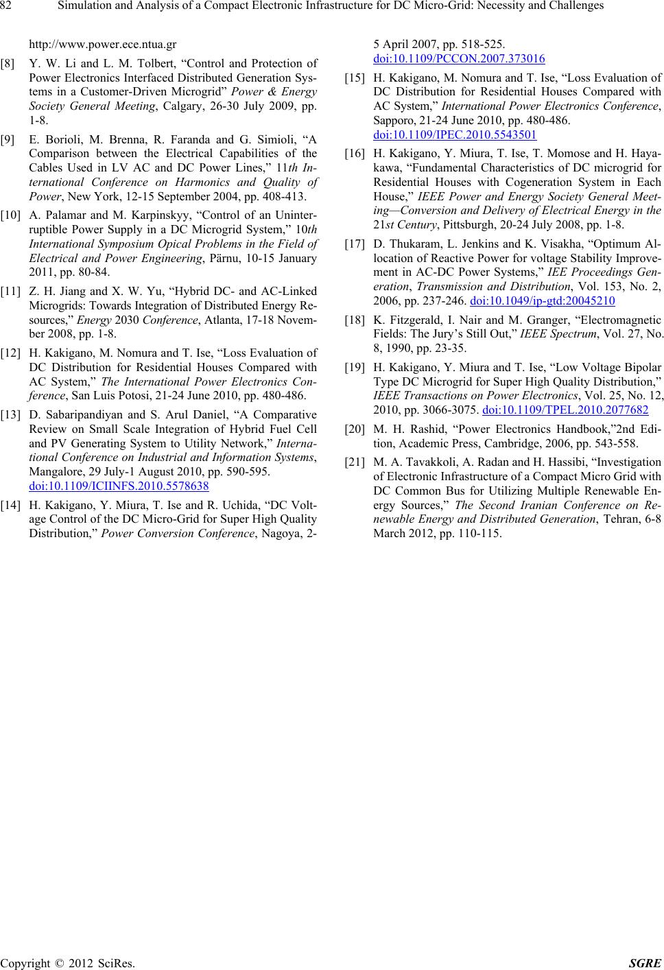 Simulation and Analysis of a Compact Electronic Infrastructure for DC Micro-Grid: Necessity and Challenges Copyright © 2012 SciRes. SGRE 82 http://www.power.ece.ntua.gr [8] Y. W. Li and L. M. Tolbert, “Control and Protection of Power Electronics Interfaced Distributed Generation Sys- tems in a Customer-Driven Microgrid” Power & Energy Society General Meeting, Calgary, 26-30 July 2009, pp. 1-8. [9] E. Borioli, M. Brenna, R. Faranda and G. Simioli, “A Comparison between the Electrical Capabilities of the Cables Used in LV AC and DC Power Lines,” 11th In- ternational Conference on Harmonics and Quality of Power, New York, 12-15 September 2004, pp. 408-413. [10] A. Palamar and M. Karpinskyy, “Control of an Uninter- ruptible Power Supply in a DC Microgrid System,” 10th International Symposium Opical Problems in the Field of Electrical and Power Engineering, Pärnu, 10-15 January 2011, pp. 80-84. [11] Z. H. Jiang and X. W. Yu, “Hybrid DC- and AC-Linked Microgrids: Towards Integration of Di stributed Energy Re- sources,” Ene rgy 2030 Conference, Atlanta, 17-18 Novem- ber 2008, pp. 1-8. [12] H. Kakiga no, M. Nomura and T. Ise , “Loss Evaluat ion of DC Distribution for Residential Houses Compared with AC System,” The International Power Electronics Con- ference, San Luis Potosi, 21-24 June 2010, pp. 480-486. [13] D. Sabaripandiyan and S. Arul Daniel, “A Comparative Review on Small Scale Integration of Hybrid Fuel Cell and PV Generating System to Utility Network,” Interna- tional Conference on Industrial and Information Systems, Mangalore, 29 July-1 August 2010, pp. 590-595. doi:10.1109/ICIINFS.2010.5578638 [14] H. Kakigano, Y. Miura, T. Ise and R. Uchida, “DC Volt- age Control of the DC Micro-Grid for Super High Quality Distribution,” Power Conversion Conference, Nagoya, 2- 5 April 2007, pp. 518-525. doi:10.1109/PCCON.2007.373016 [15] H. Kakiga no, M. Nomura and T. Ise , “Loss Evaluat ion of DC Distribution for Residential Houses Compared with AC System,” International Power Electronics Conference, Sapporo, 21-24 June 2010, pp. 480-486. doi:10.1109/IPEC.2010.5543501 [16] H. Kakigano, Y. Miura, T. Ise, T. Momose and H. Haya- kawa, “Fundamental Characteristics of DC microgrid for Residential Houses with Cogeneration System in Each House,” IEEE Power and Energy Society General Meet- ing—Conversion and Delivery of Electrical Energy in the 21st Century, Pittsburgh, 20-24 July 2008, pp. 1-8. [17] D. Thukaram, L. Jenkins and K. Visakha, “Optimum Al- location of Reactive Power for voltage Stability Improve- ment in AC-DC Power Systems,” IEE Proceedings Gen- eration, Transmission and Distribution, Vol. 153, No. 2, 2006, pp. 237-246. doi:10.1049/ip-gtd:20045210 [18] K. Fitzgerald, I. Nair and M. Granger, “Electromagnetic Fields: The Jury’s Still Out,” IEEE Spectrum, Vol. 27, No. 8, 1990, pp. 23-35. [19] H. Kakigano, Y. Miura and T. Ise, “Low Voltage Bipolar Type DC Microgrid for Super High Quality Distribution,” IEEE Transactions on Power Electronics, Vol. 25, No. 12, 2010, pp. 3066-3075. doi:10.1109/TPEL.2010.2077682 [20] M. H. Rashid, “Power Electronics Handbook,”2nd Edi- tion, Academic Press, Cambridge, 2006, pp. 543-558. [21] M. A. Tavakkoli, A. Radan and H. Hassibi, “Investigation of Electronic Infrastructure of a Compact Micro Grid with DC Common Bus for Utilizing Multiple Renewable En- ergy Sources,” The Second Iranian Conference on Re- newable Energy and Distributed Generation, Tehran, 6-8 March 2012, pp. 110-115.
|