Paper Menu >>
Journal Menu >>
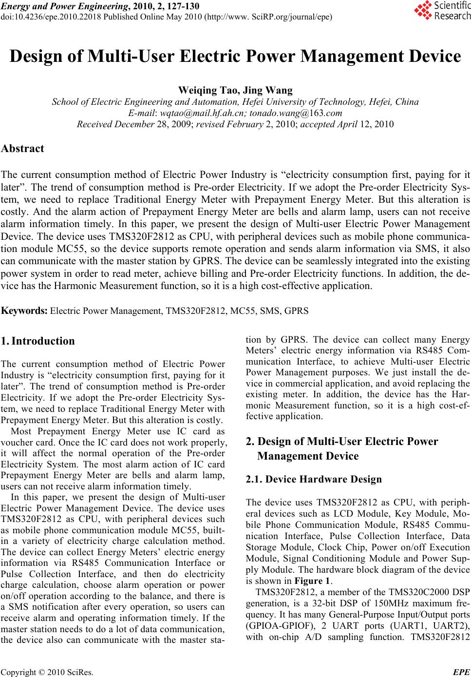 Energy and Power Engineering, 2010, 2, 127-130 doi:10.4236/epe.2010.22018 Published Online May 2010 (http://www. SciRP.org/journal/epe) Copyright © 2010 SciRes. EPE 127 Design of Multi-User Electric Power Management Device Weiqing Tao, Jing Wang School of Electric Engineering and Automation, Hefei University of Technology, Hefei, China E-mail: wqtao@mail.hf.ah.cn; tonado.wang@163.com Received December 28, 2009; revised February 2, 2010; accepted April 12, 2010 Abstract The current consumption method of Electric Power Industry is “electricity consumption first, paying for it later”. The trend of consumption method is Pre-order Electricity. If we adopt the Pre-order Electricity Sys- tem, we need to replace Traditional Energy Meter with Prepayment Energy Meter. But this alteration is costly. And the alarm action of Prepayment Energy Meter are bells and alarm lamp, users can not receive alarm information timely. In this paper, we present the design of Multi-user Electric Power Management Device. The device uses TMS320F2812 as CPU, with peripheral devices such as mobile phone communica- tion module MC55, so the device supports remote operation and sends alarm information via SMS, it also can communicate with the master station by GPRS. The device can be seamlessly integrated into the existing power system in order to read meter, achieve billing and Pre-order Electricity functions. In addition, the de- vice has the Harmonic Measurement function, so it is a high cost-effective application. Keywords: Electric Power Management, TMS320F2812, MC55, SMS, GPRS 1. Introduction The current consumption method of Electric Power Industry is “electricity consumption first, paying for it later”. The trend of consumption method is Pre-order Electricity. If we adopt the Pre-order Electricity Sys- tem, we need to replace Traditional Energy Meter with Prepayment Energy Meter. But this alteration is costly. Most Prepayment Energy Meter use IC card as voucher card. Once the IC card does not work properly, it will affect the normal operation of the Pre-order Electricity System. The most alarm action of IC card Prepayment Energy Meter are bells and alarm lamp, users can not receive alarm information timely. In this paper, we present the design of Multi-user Electric Power Management Device. The device uses TMS320F2812 as CPU, with peripheral devices such as mobile phone communication module MC55, built- in a variety of electricity charge calculation method. The device can collect Energy Meters’ electric energy information via RS485 Communication Interface or Pulse Collection Interface, and then do electricity charge calculation, choose alarm operation or power on/off operation according to the balance, and there is a SMS notification after every operation, so users can receive alarm and operating information timely. If the master station needs to do a lot of data communication, the device also can communicate with the master sta- tion by GPRS. The device can collect many Energy Meters’ electric energy information via RS485 Com- munication Interface, to achieve Multi-user Electric Power Management purposes. We just install the de- vice in commercial application, and avoid replacing the existing meter. In addition, the device has the Har- monic Measurement function, so it is a high cost-ef- fective application. 2. Design of Multi-User Electric Power Management Device 2.1. Device Hardware Design The device uses TMS320F2812 as CPU, with periph- eral devices such as LCD Module, Key Module, Mo- bile Phone Communication Module, RS485 Commu- nication Interface, Pulse Collection Interface, Data Storage Module, Clock Chip, Power on/off Execution Module, Signal Conditioning Module and Power Sup- ply Module. The hardware block diagram of the device is shown in Figure 1. TMS320F2812, a member of the TMS320C2000 DSP generation, is a 32-bit DSP of 150MHz maximum fre- quency. It has many General-Purpose Input/Output ports (GPIOA-GPIOF), 2 UART ports (UART1, UART2), with on-chip A/D sampling function. TMS320F2812  W. Q. TAO ET AL. 128 Figure 1. Hardware block diagram. is highly integrated, high-performance solutions for de- manding control applications [1]. LCD Module adopted 128*64 dot matrix LCD dis- play, controlled by TMS320F2812’s GPIOA. Because the processing speed of LCD is much slower than TMS320F2812, control signal is through the latch to control LCD. LCD refreshes every minute, displays the current power consumption and the current balance of user. It also can query information with the operation of the keys. Key Module is connected to TMS320F2812’s data bus, software control TMS320F2812 to scan data bus every 10 milliseconds. When a button is depressed, TMS320F2812 do corresponding processing according to data bus level changes. Mobile Phone Communication Module adopted MC55 of SIEMENS, which is connected to TMS320 F2812’s UART2. Administrator and user make SMS or GPRS remote operation to the device via the Mobile Phone Communication Module [3]. When the balance is insufficient, TMS320F2812 controls the module to use SMS to notify the user timely payment. The device has two meter reading ports, RS485 Communication Interface and Pulse Collection Interface. RS485 Communication Interface connects to TMS320 F2812’s UART1 via signal converter and optocoupler. UART1 sends a signal through the optocoupler and then through the signal converter to reach RS485 Commu- nication Interface, RS485 Communication Interface receives a signal through the signal converter and then through the optocoupler to reach UART1. Pulse Col- lection Interface connects to TMS320F2812’s GPIOE via optocoupler. When the pulse signal reaches GPIOE via optocoupler, TMS320F2812 gain electric energy information. We use an EEPROM chip as Data Storage Module, Data Storage Module and Clock Chip is connected to TMS320F2812 via I2C Bus. Since TMS320F2812 has no hardware I2C Bus, using GPIOB simulate the I2C Bus Timing controlled by software. Data Storage Module stored device parameters information, user information and electricity consumption records. Clock Chip provides the device with time reference for time- billing. TMS320 F2812 Power on/off Execution Module is connected to TMS320F2812’s GPIOF. The module is composed of optocoupler, relay and breaker. The controlling signals go through an optocoupler safety quarantined, and then go through the relay reach breaker, at last breaker re- sponses the control signal. Signal Conditioning Module is composed of CT and PT. The regulated signal followed by the filter circuit, voltage divider circuit. At last input TMS320F2812’s on-chip A/D as differential mode to achieve Harmonic Measurement function. Power Supply Module is composed of working power and backup power. Working power is obtained directly from the feeder and do battery charging at same time. Backup power is composed of battery. 2.2. Device SMS Function The device can do Buy Operation, Inquire Operation, Power On/Off Operation, and Change Parameters Op- eration by SMS communication. It also can Send Alarm SMS on its own initiative. Buy Operation means that administrator add user’s balance by sending encrypted SMS. Inquire Operation means that administrator or user inquire balance by sending SMS. Power On/Off Operation means that administrator can make power on/off operation by send- ing encrypted SMS. Change Parameters Operation means that administrator can change electricity charge parameters by sending encrypted SMS [5]. Send Alarm SMS means that the device can send alarm SMS on its own initiative when the balance is less than some value. The device stored some cell phone numbers. These numbers are divided into administrator number and user number. The device handles the messages as this flow: first Phone Number Analysis, then Operation Type Analysis, at last Response Operation. Received SMS processing flow is shown in Figure 2. Phone Number Analysis means that, to judge the sender's number is administrator number or user num- ber by comparing the sender's number with the num- bers stored in the device. If the sender's number is not in the stored number list, delete this SMS, the device take no action. Operation Type Analysis means that, the device gets Copyright © 2010 SciRes. EPE  W. Q. TAO ET AL.129 Figure 2. Received SMS processing flow. operation information by analyzing SMS, and deter- mines whether the operation is allowable. Administra- tor can do Buy Operation, Inquire Operation, Power On/Off Operation, and Change Parameters Operation. User can do Inquire Operation. If the SMS senders want to do limited operation, the device will return an authority error message to them. Response Operation means that, the device makes different operations according to the type of operation. All operations have SMS receipt to inform the operator if the operation is successful or not. In addition, the device send alarm SMS to adminis- trator number and user number, when the balance is less than some value. 2.3. Device GPRS Function The device also has GPRS communication function. Since the bytes of a SMS is limited, if we need to do a lot of data communication, using multiple SMS to communication is costly. For example, query operation history, query harmonic measurement records, in this case, the device communicates with the master station by GPRS. 3. Possible Commercial Applications In this Pre-order Electricity System, PC master station controls a mobile phone communication module as an administrator with the Host Computer Software. Users carry mobile phones as a user number. The device collects multiple Energy Meter’s infor- mation via RS485 Bus. It can manage and control mul- tiple meter users. In commercial applications, we do not need to replace the existing meter by Prepayment Energy Meter, just installing the Pre-order Electricity device on the basis of the existing system. The Figure 3. Application of multi-user electric power manage- ment device. device used to collect Energy Meter’s information, calculate electricity and achieve Pre-order Electricity functions. The possible application of Pre-order Elec- tricity device is shown in Figure 3. If the Energy Meter does not have RS485 Commu- nication function, the device can collect electric energy information by Pulse Collection Interface. This situa- tion the device can only manage one Energy Meter. 4. Conclusions In this paper, we present a design of a Multi-user Electric Power Management Device. We use high-inte- grated and high-performance DSP TMS320F2812 as CPU, with peripheral devices such as mobile phone communication module MC55. The device can deal with complicated control information. It has three fea- tures: 1) Two kinds of electric energy information collect mode, it can manage and control multiple meter users. 2) Automatic calculation electricity charge based on different user information and electric energy informa- tion. 3) With the ability of remote operation via SMS and GPRS, and sending alarm information via SMS. The device can be seamlessly integrated into the ex- isting power system in order to read meter, achieve billing and Pre-order Electricity functions, can manage and control multiple meter users. In addition, the de- vice has the Harmonic Measurement function. The application of the device can reduce the cost of the system reform, and it has been successfully used in Wuhu city of Anhui Province in China. 5 . References [1] Texas Instruments Incorporated, TMS320F281x Data Sheet, 2005. [2] Texas Instruments Incorporated, TMS320F28x Optimiz- ing C/C ++ Compiler User’s Guide, 2005. SMS GPRS RS485 BUS Copyright © 2010 SciRes. EPE  W. Q. TAO ET AL. Copyright © 2010 SciRes. EPE 130 [3] SIEMENS Mobile, SIEMENS. MC55/56 Hardware In- terface Description, 2006. [4] SIEMENS Mobile, SIEMENS. MC55/56 AT Command Set, 2003. [5] J. F. Wang, W. Q. Tao and L. L. Wang, “Design of Mod- ify the Parameters of LTU by Using SMS,” Microcon- trollers & Embedded Systems, Vol. 6, 2009, pp. 40-42. [6] Jiangsu Electric Power Company, Power Marketing Knowledge Q & A (Part of the electricity tariff), China Electric Power Press, Beijing, 2004. [7] Z. B. Jiang, “Power Management/Technical Expertise for the Use of Electricity,” China Electric Power Press, Bei- jing, 2002. |