Smart Grid and Renewable Energy, 2012, 3, 1-9
http://dx.doi.org/10.4236/sgre.2012.31001 Published Online February 2012 (http://www.SciRP.org/journal/sgre)
1
Study of Micro Grid Safety & Protection Strategies with
Control System Infrastructures
Md Razibul Islam, Hossam A. Gabbar
Faculty of Energy System and Nuclear Science, University of Ontario Institute of Technology, Oshawa, Canada.
Email: razu_49@hotmail.com, hossam.gabbar@uoit.ca
Received October 2nd, 2011; revised November 2nd, 2011; accepted November 10th, 2011
ABSTRACT
Microgrids have been proposed in order to improve reliability and stability of electrical system and to ensure power
quality of grid. Microgrid consists of low voltage distribution systems with distributed energy resources, such as wind
turbine and photovoltaic power systems, together with storage devices. It is essential to protect a micro grid in both the
grid-connected and the islanded mode of operation against all different types of faults. This paper describes micro grid
protection and safety concept with central control and monitoring unit where multifunctional intelligent digital relay
could be used. This central control & monitoring infrastructure is used for adaptive relay settings strategy for micro grid
protection. Also operational safety design concept and fault mitigation technique is proposed to ensure confidence in
protection system.
Keywords: Micro Grid (MG); Distributed Generator (DG); Micro Grid Central Control (MCC)
1. Introduction
With the development of renewable energy, energy stor-
age and distributed generation (DG) the microgrid has
attracted more and more concern due to its special fea-
tures. A micro grid consists of a low to medium voltage
network of small load clusters with DG sources and stor-
age. Micro grids can operate in an islanded mode or can
be connected to the main grid system. If a micro grid is
connected to the system, it is seen as a single aggregate
load or source. One of the potential advantages of a mi-
cro grid is that it could provide a more reliable supply to
customers by islanding from the system in the event of a
major disturbance. As distributed generator placed/situ-
ated close to the load, it has the advantage of reducing
transmission losses as well as preventing network con-
gestions [1,2]. Thus distributed generator can enhance
system reliability and stability.
Micro grids currently offer various advantages to end-
consumers, utilities and society, such as: Improved ener-
gy efficiency, improve power quality and reliability, mi-
nimized overall energy consumption, reduced green-
house gases and pollutant emissions, cost efficient elec-
tricity infrastructure replacement [1-5].
2. Intelligent Protection Strategy of Micro
Grid
One of the major challenges of micro grid protection system
is that it must respond to both island and grid connected
faults [1-13]. In the first case the protection system
should isolate the smallest part of the micro grid when
clears the fault. In the second case the protection system
should isolate the micro grid from the main grid as
rapidly as necessary to protect the micro grid loads [1-
3].
Modern micro grid consist of many different distri-
buted energy resources like solar PV, wind turbines, fuel
cells, small-scale hydro, tidal and wave generators, micro-
turbines, combined heat power (CHP) systems, energy
storage, etc.. When different type of distributed resource
connected to micro grid and Utility grid, the DR contri-
bute fault current to the system and the contribution level
depends on distribution resource type. To ensure safe
operation of micro grid the protection equipment should
be updated accordingly.
So the dynamic structure of micro grid and their
various operating conditions required the development of
adaptive protection strategies. One such strategy is
proposed in Figure 1. Here central control unit commu-
nicate with all relays and distributed generators in the
micro grid to record their status as ON/OFF, their rated
current and their fault current contribution. Communicate
with relay is required to update the operating current and
to detect the direction of the fault currents and thus
mitigate the fault properly. The control unit also records
the status of utility grid as connected or micro grid is
Copyright © 2012 SciRes. SGRE
Study of Micro Grid Safety & Protection Strategies with Control System Infrastructures
2
Figure 1. Topology of micro grid protection system.
islanded for adaptive protection.
3. Operational Safety Design Concept of
Micro Grid
Safety analysis or safety design concept is important in
micro grid protection and their fault analysis. Proper
safety model provides appropriate level of confidence in
protection system.
The intelligent control and monitoring unit need to
meet the safety requirements which provide on basis of
safety design criteria. Proposed operational safety of mi-
cro grid is shown in Figure 2. Central control and pro-
tection system should design to ensure required safety.
Micro grid hazard analysis is important to design safety
system and based on hazard level different safety thresh-
old is settled. For micro grid safety design there are six
parameters need to consider which are shown in Figure
2.
Figure 2. Operational safety design of micro grid.
Copyright © 2012 SciRes. SGRE
Study of Micro Grid Safety & Protection Strategies with Control System Infrastructures 3
The first one is sensitivity, there should have nominal
threshold value and control/protection system able to
identify any abnormal condition. This nominal value
should be set considering safety level of all power system
equipment’s. Second is selectivity, when fault detected in
a system based on voltage, current and power direction
fault zone is determined. In order to minimize fault con-
sequence, the protection/control system should discon-
nect only the faulted part (Disconnect smallest possible
part containing the fault). Third one is speed, in order to
avoid damage to equipment and maintain stability pro-
tective relay should respond in the least possible time in
any abnormal condition. This is very important from
safety point of views.
The security level should be high, all the abnormal
conditions/events of power system are not fault. So pro-
tection/control system should operate only when required
to operate, reject all abnormal events and transients those
are not fault. And the protection system should be de-
signed to avoid misoperation while itself experiencing a
credible failure. There should have redundancy options,
redundant system are planned and referred as backup
protection to ensure level of safety. The protection sys-
tem should have redundant functionalities of relays to
improve system reliability and safety. Different protec-
tion principle could be combining to reach protection
redundancy. The reliability should be high, modern power
system with distributed generator becoming more dyn-
amic structure, so now reliability becomes important
topic in control and protection system analysis. Based on
different system condition there should have option for
different relay setting. To improve modern protection
and control system reliability and faster restoration of
outage, we can use microprocessor based distribution
relay or digital relay.
The above safety model could guarantee micro grid
protection. We need to consider this safety model for
both island and grid connected operation. It is essential to
protect a micro grid in both the grid-connected and the
islanded modes of operation against all types of faults.
The major issue arises in island operation with in-
verter-based sources. Inverter fault currents are limited
by the ratings of the silicon devices to around 2 p.u. rated
current. Fault currents in islanded inverter based micro
grids may not have adequate magnitudes to use tradi-
tional over-current protection techniques. This possibility
requires an expanded protection strategy [2,3].
Based on safety analysis a modern micro grid opera-
tional model for different relay settings is shown in Fig-
ure 3. In this proposed system, the central unit commu-
nicates with every single relay and distributed generator
in the micro grid on interruption basis. The central con-
trol and monitoring unit record the instantaneous status
of the distributed generator and utility grid as connected/
disconnected, their rated currents and their fault current
contributions.
To overcome protection challenge of islanded and grid
connected system different relay settings are required.
Once a distributed generator connected/disconnected in
system, based on island or grid connected, new relay
Figure 3. Micro grid operation model for different relay settings strategy.
Copyright © 2012 SciRes. SGRE
Study of Micro Grid Safety & Protection Strategies with Control System Infrastructures
4
settings are updated, new fault currents are updated in
relays. Relays operate independently to open the connec-
tions. Once the current flowing over the relay exceeds
the operating current, relays send signals to set the fault
detection bit.
4. Micro Grid Fault Analysis with System
Modeling
In micro grid fault analysis we can categorize mainly two
type, external fault (main grid) and internal fault (micro
grid). External fault could be in MV bus or distribution
transformer and internal fault could be in LV feeder or
LV consumer. As micro grid need to operate in both is-
land and grid connected mode there have challenge in
micro grid protection system with conventional protec-
tion strategy [1-5]. The major micro grid protection prob-
lem is related to large difference between fault current in
main grid connected and islanded mode.
Also there have sensitivity and selection problem due
to different fault current in different scenario [1,4]. But it
is essential to have high sensitive to faults and selectively
isolate/sectionalize in the case of DGs with low fault
current level. As conventional protection system don’t
offer solution for all micro grid protection challenge,
advanced protection strategy required.
Intelligent Protection Techniques for Micro Grid
Here a model of adaptive/intelligent protection system
for micro grid is shown in Figure 4. This advanced pro-
tection system can potentially solve the problems identi-
fied earlier. The protection scheme must ensure safe op-
eration of the micro grid in both mode of operation, that
is the grid connected mode and island mode. Due to con-
tribution of host grid in grid connected mode fault cur-
rents are large. This allows to employment of conven-
tional overcurrent relay, but the fact is that due to exis-
tence of distributed resources (DRs) the protection coor-
dination may be compromised or even entirely loss in
some cases [10].
However, in islanded mode due to limited current con-
Figure 4. Centralized protection system for micro grid.
Copyright © 2012 SciRes. SGRE
Study of Micro Grid Safety & Protection Strategies with Control System Infrastructures 5
tribution of distributed resource fault current may be sig-
nificantly small compared to grid connected mode. For
this reason the conventional over current protection is
ineffective in islanded mode of operation [10].
Proposed adaptive protection system can solve the
challenge of conventional micro grid protection system.
The new protection system modifies the preferred pro-
tection response to a change in system conditions in a
timely manner by means of externally generated signal or
advanced control actions [1]. For a practical implementa-
tion of adaptive micro grid protection the requirements
and suggestion can be mentioned as below:
Firstly, there would have a micro grid central control-
ler (MCC) and monitoring system in modern micro grid
protection system. Communication electronics make each
CB with an integrated directional OC electronic trip unit
(relay) capable of exchanging information with MCC.
Secondly, use of numerical directional OC relays/mi-
croprocessor based relay/digital relay because fuses or
electromechanical and standard solid state relays are
(especially for selectivity holding) inapplicable—they do
not provide the flexibility for changing the settings of
tripping characteristics and they have no current direction
sensitivity feature.
Thirdly, numerical directional OC relays/microproc-
essor based relays must dispose of possibility for using
different tripping characteristics (several settings groups)
that can be parameterized locally or remotely automati-
cally or manually [1,14].
Finally, introduce modern control infrastructure and
data acquisition protocols so that individual relays can
communicate and exchange information with micro grid
central controller (MCC). With this instantaneous set-
tings for different fault scenario which will reliably to
guarantee a required application performance.
The modern Micro grid protection system with micro
grid central control and monitoring system is an impor-
tant topic to discuss to overcome challenge of conven-
tional protection system. Instantaneous relay settings,
current, voltage and power directions are sent to central
control unit through micro grid monitoring and data ac-
quisition unit.
So with MCC and monitoring unit any abnormal con-
dition or disturbance can be monitor and measure. Based
on disturbance data analysis the fault could be detected,
when any fault is detected it is important to find fault
type based on current state of micro grid and the fault
affected area/zone.
The main goal of intelligent protection system is to
maintain relay setting of each relay with current micro
grid scenario. There would be a special module in micro
grid central control (MCC) unit which is responsible for
periodic check and update of relay settings [1,2]. The
Micro grid central control (MCC) can read data (direc-
tion, electrical value, status) of individual relays from
each CB and if required it can modify subset of relay
settings (tripping characteristics).
So tripping decision can perform by MCC to each in-
dividual relay, in case of any abnormal situation is de-
tected tripping condition is checked and the direction of
current is measured compared with actual relay settings
[1,2,14].
5. Fault Mitigation Technique of Micro Grid
A simple model of micro grid protection structure and
fault mitigation process is described in Figure 5. Micro
grid protection system and fault analysis done based on
data acquisition from control and monitoring unit. Based
on data acquisition disturbance is measured and fault
detection alarm found based on disturbance value.
At first fault should be determined by detecting change
in bus bar voltage. Power direction is measured and
based on this fault location detected. The fault point is in
the utility grid if the power direction of the common
connection point of utility grid and point of micro grid is
positive. The direction of bus bar pointing to the line sets
as power positive direction. According to the power di-
rections of the lines connected to bus bar, the system can
determine whether there is a bus short-circuit fault.
The fault is a bus short circuit fault and breakers of
Figure 5. Fault mitigation technique of micro grid.
Copyright © 2012 SciRes. SGRE
Study of Micro Grid Safety & Protection Strategies with Control System Infrastructures
6
each side of bus trip, if the power directions of all micro
source lines are negative directions. Based on power di-
rection inner fault, bus fault, line fault is determined.
Once line fault is detected fault area/zone is determined
and then fault is removed by tripping signal from relay.
6. Case Study on Micro Grid Protection
An example of intelligent protection system is shown in
Figure 6 [2,6]. Here micro grid central controller (MCC)
and monitoring system is included in conventional pro-
tection system. MCC is carried out by a programmable
logic controller (PLC), a station computer sitting in MV/
LV substation. The function of communication electron-
ics is to make each circuit breaker with an integrated
over current relay capable of exchanging information
with MCC [6].
MCC can read data (electrical value, status) from CBs
if necessary it can modify relay settings. When any ab-
normal condition is detected a tripping condition is
checked, if tripping condition is reached a CB is open.
For fault analysis we assume micro grid with distrib-
uted energy resource switched on the grid. Let assume
there is a considerable change in micro grid and status of
distributed energy resource.
SWB4 and SWB5 is disconnected for a maintenance
work and SWB5 and SWB6 are supplied via SWB3
(CB3.2 and CB6.2 are closed) which is shown in Figure
7 from reference [2]. Two identical distributed generators
are connected with SWB1 and SWB6 [2].
Now we analyze the fault between SWB1 and SWB2
(Figure 7), it is required to isolate the fault from the
main grid side by CB1.2 and there is no selectivity and
detection problem, also because the fault current seen by
CB1.2 becomes higher Ikmax = 15 kA (Figure 8) in the
base case due to a contribution from the distributed re-
source in SWB1. CB2.1 is seen 2 kA fault current sup-
plied by second distributed generator in SWB6. It can
only activate the L part of the relay’s trip curve with the
expected tripping time delay of 40 s. So, by the (follow-
me) function of CB1.2, CB2.1 is opened and isolates the
fault from the LV feeder side in ts = 150 ms [2].
Here noticeable thing is ts 150 ms set for the OC re-
lay in CB1.2 which may affect a stability of the distrib-
uted generator with a small inertia in SWB1. For all relay
in the micro grid the time delay ts is set at 50 ms. Then
blocking signals are sent in correct directions which pre-
vents an unnecessarily disconnection of distributed re-
sources and healthy parts of the micro grid [2].
Now we assume that after an isolation of the first fault
occurred in between SWB1 and SWB2, the island which
includes SWB2, 3, 5, 6. The Distributed generator in
SWB6 is switched to a frequency control mode and addi-
tionally each load in the island is dropped from 100 A to
50 A.
Assume in between SWB2 and SWB3 there is a sec-
ond fault inside the islanded micro grid and all non-di-
rectional OC relays use ts settings from the base case [2].
Ideally, the fault should be cleared by CB2.2 and CB3.1.
Since there is no fault current source in SWB2, CB2.2
can’t trip but it can be opened by the “follow-me” func-
tion of CB3.1. In case of using directional OC protection
ts = 150 ms for CB3.1 [2]. However, the maximum fault
current supplied by the synchronous DER in SWB6 and
seen by CB3.1 Ikmax = 2.4 kA shown in Figure 9.
Figure 6. Micro grid protection system infrastructure.
Copyright © 2012 SciRes. SGRE
Study of Micro Grid Safety & Protection Strategies with Control System Infrastructures 7
Figure 7. Micro grid protection system with central controller unit.
Figure 8. Base case trip curve and tripping sequence with directional overcurrent protection.
This will activate the L part of the relay’s trip curve
with the expected tripping time delay of 25 s. During this
time distributed generator in SWB6 will be disconnected
by its out-of-step protection.
In island mode where the main grid does not contrib-
ute to the fault, to guarantee fast fault isolation the trip
curve must be pushed to the left dynamically depending
on the micro grid topology and a number of connected
DG. The modified trip curves are illustrated in Figure 9
[2,15].
7. Conclusions
Modern numerical relay normally offer several settings
group which can be activated at any time. It can achieve
instantaneous tripping in different fault and operation
scenario. One of the challenges of micro grid protection
is to operate during normal and island operation which
could be solved by modern numerical relay with micro
grid central control and monitoring unit.
In this paper, an intelligent micro grid protection sys-
em using digital relaying with central control and moni- t
Copyright © 2012 SciRes. SGRE
Study of Micro Grid Safety & Protection Strategies with Control System Infrastructures
8
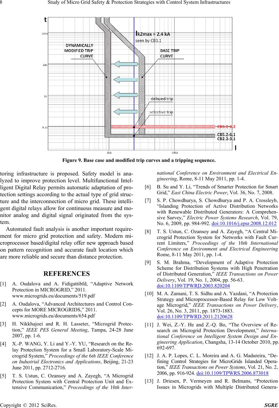
Figure 9. Base case and modified trip curves and a tripping sequence.
toring infrastructure is proposed. Safety model is ana-
lyzed to improve protection level. Multifunctional Intel-
ligent Digital Relay permits automatic adaptation of pro-
tection settings according to the actual type of grid struc-
ture and the interconnection of micro grid. These intelli-
gent digital relays allow for continuous measure and mo-
nitor analog and digital signal originated from the sys-
tem.
Automated fault analysis is another important require-
ment for micro grid protection and safety. Modern mi-
croprocessor based/digital relay offer new approach based
on pattern recognition and accurate fault location which
are more reliable and secure than distance protection.
REFERENCES
[1] A. Oudalova and A. Fidigattibfd, “Adaptive Network
Protection in MICROGRID,” 2011.
www.microgrids.eu/documents/519.pdf
[2] A. Oudalova, “Advanced Architectures and Control Con-
cepts for MORE MICROGRIDS,” 2011.
www.microgrids.eu/documents/654.pdf
[3] H. Nikkhajoei and R. H. Lasseter, “Microgrid Protec-
tion,” IEEE PES General Meeting, Tampa, 24-28 June
2007, pp. 1-6.
[4] X.-P. WANG, Y. Li and Y.-Y. YU, “Research on the Re-
lay Protection System for a Small Laboratory-Scale Mi-
crogrid System,” Proceedings of the 6th IE EE C onference
on Industrial Electronics and Applications, Beijing, 21-23
June 2011, pp. 2712-2716.
[5] T. S. Ustun, C. Ozansoy and A. Zayegh, “A Microgrid
Protection System with Central Protection Unit and Ex-
tensive Communication,” Proceedings of the 10th Inter-
national Conference on Environment and Electrical En-
gineering, Rome, 8-11 May 2011, pp. 1-4.
[6] B. Su and Y. Li, “Trends of Smarter Protection for Smart
Grid,” East China Electric Power, Vol. 36, No. 7, 2008.
[7] S. P. Chowdhurya, S. Chowdhurya and P. A. Crossleyb,
“Islanding Protection of Active Distribution Networks
with Renewable Distributed Generators: A Comprehen-
sive Survey,” Electric Power Systems Research, Vol. 79,
No. 6, 2009, pp. 984-992. doi:10.1016/j.epsr.2008.12.012
[8] T. S. Ustun, C. Ozansoy and A. Zayegh, “A Central Mi-
crogrid Protection System for Networks with Fault Cur-
rent Limiters,” Proceedings of the 10th International
Conference on Environment and Electrical Engineering
Rome, 8-11 May 2011, pp. 1-4.
[9] S. M. Brahma, “Development of Adaptive Protection
Scheme for Distribution Systems with High Penetration
of Distributed Generation,” IEEE Transactions on Power
Delivery, Vol. 19, No. 1, 2004, pp. 56-63.
doi:10.1109/TPWRD.2003.820204
[10] M. A. Zamani, T. S. Sidhu and A. Yazdani, “A Protection
Strategy and Microprocessor-Based Relay for Low Volt-
age Microgrid,” IEEE Transactions on Power Delivery,
Vol. 26, No. 3, 2011, pp. 1873-1883.
doi:10.1109/TPWRD.2011.2120628
[11] J. Wei, Z.-Y. He and Z.-Q. Bo, “The Overview of Re-
search on Microgrid Protection Development,” Interna-
tional Conference on Intelligent System Design and En-
gineering Application, Changsha, 13-14 October 2010, pp.
692-697.
[12] J. A. P. Lopes, C. L. Moreira and A. G. Madureira, “De-
fining Control Strategies for MicroGrids Islanded Opera-
tion,” IEEE Transactions on Power Systems, Vol. 21, No. 2,
2006, pp. 916-924. doi:10.1109/TPWRS.2006.873018
[13] J. Driesen, P. Vermeyen and R. Belmans, “Protection
Issues in Microgrids with Multiple Distributed Genera-
Copyright © 2012 SciRes. SGRE
Study of Micro Grid Safety & Protection Strategies with Control System Infrastructures 9
tion Units,” IEEE Power Conversion Conference, Nagoya,
2-5 April 2007, pp. 646-653.
doi:10.1109/PCCON.2007.373034
[14] E. Sortomme, S. S. Venkata and J. Mitra, “Microgrid Pro-
tection Using Communication-Assisted Digital Relays,”
IEEE Transactions on Power Delivery, Vol. 25, No. 4,
2010, pp. 2789-2796.
[15] ABB SACE, “Working with the Trip Characteristic Curves
of ABB SACE Low Voltage Circuit Breakers,” White
Paper, Vol. 1, 2007. http://www.abb.com/
Copyright © 2012 SciRes. SGRE