Paper Menu >>
Journal Menu >>
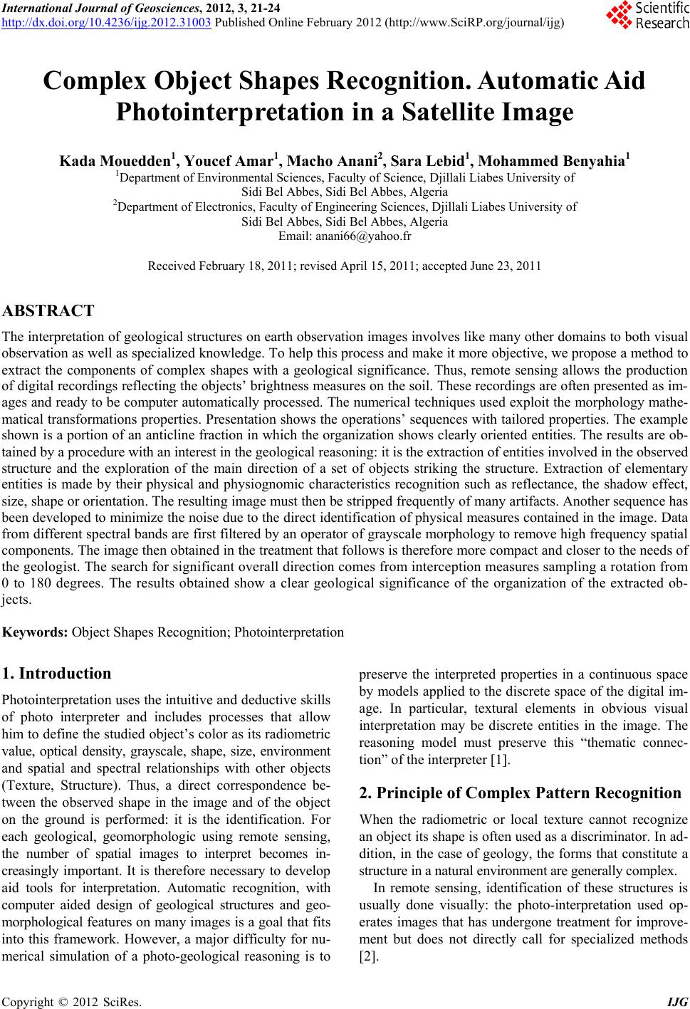 International Journal of Geosciences, 2012, 3, 21-24 http://dx.doi.org/10.4236/ijg.2012.31003 Published Online February 2012 (http://www.SciRP.org/journal/ijg) Complex Object Shapes Recognition. Automatic Aid Photointerpretation in a Satellite Image Kada Mouedden1, Youcef Amar1, Macho Anani2, Sara Lebid1, Mohammed Benyahia1 1Department of Envir o n me n t a l Sciences, Faculty of Science, Djillali Liabes University of Sidi Bel Abbes, Sidi Bel Abbes, Algeria 2Department of Electronics, Faculty of Engineering Sciences, Djillali Liabes University of Sidi Bel Abbes, Sidi Bel Abbes, Algeria Email: anani66@yahoo.fr Received February 18, 2011; revised April 15, 2011; accepted June 23, 2011 ABSTRACT The interpretation of geological structures on earth observatio n images involves like man y other domains to both visual observation as well as specialized knowledge. To help this process and make it more objective, we propose a method to extract the components of complex shapes with a geological significance. Thus, remote sensing allows the production of digital recordings reflecting the objects’ brightness measures on the soil. These recordings are often presented as im- ages and ready to be computer automatically processed. The numerical techniques used exploit the morphology mathe- matical transformation s properties. Presentation shows the operations’ sequen ces with tailored properties. The example shown is a portion of an anticline fraction in which the organization shows clearly oriented entities. The results are ob- tained by a procedure with an interest in the geological reasoning: it is the extraction of entities involved in the observed structure and the exploration of the main direction of a set of objects striking the structure. Extraction of elementary entities is made by their physical and physiognomic characteristics recognition such as reflectance, the shadow effect, size, shape or orientation. The resulting image must then be stripped frequently of many artifacts. Another sequence has been developed to minimize the noise due to the direct identification of physical measures contained in the image. Data from different spectral bands are first filtered by an operator of grayscale morphology to remove high frequency spatial components. The image then obtained in the treatment that follows is therefore more compact and closer to the needs of the geologis t. The sear ch for sign ifican t overall di rection comes from interception measures sampling a rotation from 0 to 180 degrees. The results obtained show a clear geological significance of the organization of the extracted ob- jects. Keywords: Object Shapes Recognition; P h o tointerpr et a t i on 1. Introduction Photointerpretation uses the intuitiv e and deductive skills of photo interpreter and includes processes that allow him to define the studied object’s color as its radiometric value, optical density, grayscale, shape, size, environment and spatial and spectral relationships with other objects (Texture, Structure). Thus, a direct correspondence be- tween the observed shape in the image and of the object on the ground is performed: it is the identification. For each geological, geomorphologic using remote sensing, the number of spatial images to interpret becomes in- creasingly important. It is therefore necessary to develop aid tools for interpretation. Automatic recognition, with computer aided design of geological structures and geo- morphological featu res o n many image s is a goal t hat fi ts into this framework. However, a major difficulty for nu- merical simulation of a photo-geological reasoning is to preserve the interpreted properties in a continuous space by models applied to the discrete space of the digital im- age. In particular, textural elements in obvious visual interpretation may be discrete entities in the image. The reasoning model must preserve this “thematic connec- tion” of the interpreter [1]. 2. Principle of Complex Pattern Recognition When the radiometric or local texture cannot recognize an object its shape is often used as a discriminator. In ad- dition, in the case of geology, the forms that constitute a structure in a natural environment are generally complex. In remote sensing, identification of these structures is usually done visually: the photo-interpretation used op- erates images that has undergone treatment for improve- ment but does not directly call for specialized methods [2]. C opyright © 2012 SciRes. IJG 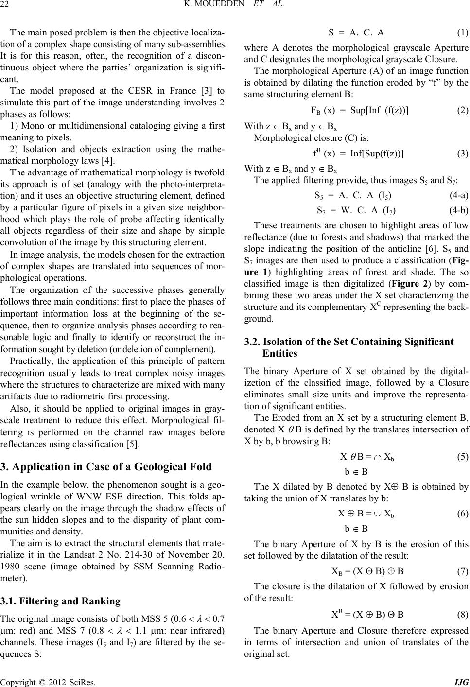 K. MOUEDDEN ET AL. 22 The main posed problem is then the objective localiza- tion of a complex shape consisting of many sub-assemblies. It is for this reason, often, the recognition of a discon- tinuous object where the parties’ organization is signifi- cant. The model proposed at the CESR in France [3] to simulate this part of the image understanding involves 2 phases as follows: 1) Mono or multidimensional cataloging giving a first meaning to pixels. 2) Isolation and objects extraction using the mathe- matical morphology laws [4]. The advantage of mathe matical morphology is twofo ld: its approach is of set (analogy with the photo-interpreta- tion) and it uses an objective structuring element, defined by a particular figure of pixels in a given size neighbor- hood which plays the role of probe affecting identically all objects regardless of their size and shape by simple convolution of the image by this stru cturing element. In image analysis, the models chosen for the extraction of complex shapes are translated into sequences of mor- phological operation s. The organization of the successive phases generally follows three main conditions: first to place th e phases of important information loss at the beginning of the se- quence, then to organize analysis phases according to rea- sonable logic and finally to identify or reconstruct the in- formation sought by deletion (or deletion of complement). Practically, the application of this principle of pattern recognition usually leads to treat complex noisy images where th e structur es to char acterize are mixed w ith many artifacts due to radiometric first processing. Also, it should be applied to original images in gray- scale treatment to reduce this effect. Morphological fil- tering is performed on the channel raw images before reflectances using classification [5]. 3. Application in Case of a Geological Fold In the example below, the phenomenon sought is a geo- logical wrinkle of WNW ESE direction. This folds ap- pears clearly on the image through the shadow effects of the sun hidden slopes and to the disparity of plant com- munities and density. The aim is to extract the structural elements that mate- rialize it in the Landsat 2 No. 214-30 of November 20, 1980 scene (image obtained by SSM Scanning Radio- meter). 3.1. Filtering and Ranking The original image consists of both MSS 5 (0.6 0.7 m: red) and MSS 7 (0.8 1.1 m: near infrared) channels. These images (I5 and I7) are filtered by the se- quences S: S = A. C. A (1) where A denotes the morphological grayscale Aperture and C designates the morphological grayscale Closure. The morphological Aperture (A) of an image function is obtained by dilating the function eroded by “f” by the same structuring element B: FB (x) = Sup[Inf (f(z))] (2) With z Bx and y Bx Morphological closure (C) is: fB (x) = Inf[Sup(f(z))] (3) With z Bx and y Bx The applied filtering provide, thus images S5 and S7: S5 = A. C. A (I5) (4-a) S7 = W. C. A (I7) (4-b) These treatments are chosen to highlight areas of low reflectance (due to forests and shadows) that marked the slope indicating the position of the anticline [6]. S5 and S7 images are then used to produce a classification (Fig- ure 1) highlighting areas of forest and shade. The so classified image is then digitalized (Figure 2) by com- bining these two areas under the X set characterizing the structure and its complemen tary XC representing the back- ground. 3.2. Isolation of the Set Containing Significant Entities The binary Aperture of X set obtained by the digital- izetion of the classified image, followed by a Closure eliminates small size units and improve the representa- tion of significant entities. The Eroded from an X set by a structuring element B, denoted X B is defined by the translates intersection of X by b, b browsing B: X B = Xb (5) b B The X dilated by B denoted by X B is obtained by taking the union of X translates by b: X B = Xb (6) b B The binary Aperture of X by B is the erosion of this set followed by the dilatation of the result: XB = (X B) B (7) The closure is the dilatation of X followed by erosion of the result: XB = (X B) B (8) The binary Aperture and Closure therefore expressed in terms of intersection and union of translates of the original set. Copyright © 2012 SciRes. IJG 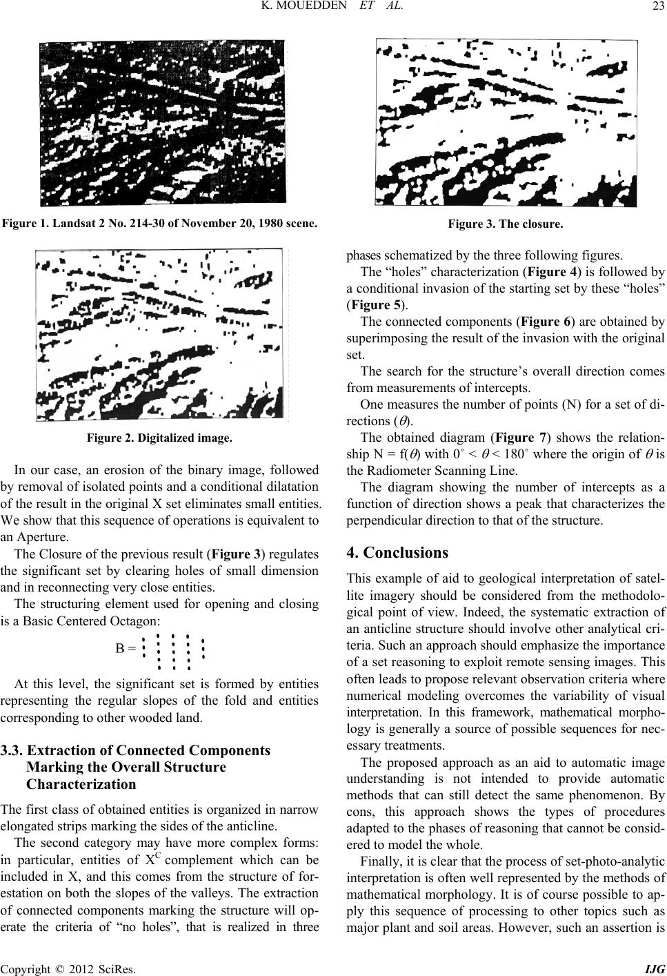 K. MOUEDDEN ET AL. 23 Figure 1. Landsat 2 No. 214-30 of November 20, 1980 scene. Figure 2. Digitalized image. In our case, an erosion of the binary image, followed by removal of isolated po ints and a cond itional dilatation of the result in the original X set eliminates small entities. We show that this sequence of operations is equivalent to an Aperture. The Closure of th e pr eviou s resu lt (Figure 3) regulates the significant set by clearing holes of small dimension and in reconnecting very close entities. The structuring element used for opening and closing is a Basic Centered Octagon: At this level, the significant set is formed by entities representing the regular slopes of the fold and entities corresponding to other wooded land. 3.3. Extraction of Connected Components Marking the Overall Structure Characterization The first class of obtained entities is organ ized in narrow elongated strips marking the sides of the anticline. The second category may have more complex forms: in particular, entities of XC complement which can be included in X, and this comes from the structure of for- estation on both the slopes of the valleys. The extraction of connected components marking the structure will op- erate the criteria of “no holes”, that is realized in three Figure 3. The closure. phases schematized by the three following figures. The “holes” characterization (Figure 4) is followed by a conditional invasion of th e starting set by these “holes” (Figure 5). The connected components (Figure 6) are obtained by superimposing the result of the invasion with the original set. The search for the structure’s overall direction comes from measurements of intercepts. One measures the number of points (N) for a set of di- rections ( ). The obtained diagram (Figure 7) shows the relation- ship N = f( ) with 0˚ < < 180˚ wher e the origin of is the Radiometer Scanning Line. The diagram showing the number of intercepts as a function of direction shows a peak that characterizes the perpendicular direction to that of the structure. 4. Conclusions This example of aid to geological interpretation of satel- lite imagery should be considered from the methodolo- gical point of view. Indeed, the systematic extraction of an anticline structure should involve other analytical cri- teria. Such an approach should emphasize the importance of a set reasoning to exploit remote sensing images. This often leads to propose relevant observation criteria where numerical modeling overcomes the variability of visual interpretation. In this framework, mathematical morpho- logy is generally a source of possible sequences for nec- essary treatments. The proposed approach as an aid to automatic image understanding is not intended to provide automatic methods that can still detect the same phenomenon. By cons, this approach shows the types of procedures adapted to the phases of reasoning that cannot be consid- ered to model the whole. Finally, it is clear that the process of set-photo-analytic interpretation is often well represented by the methods of mathematical morphology. It is of course possible to ap- ply this sequence of processing to other topics such as major plant and soil areas. However, such an assertion is Copyright © 2012 SciRes. IJG  K. MOUEDDEN ET AL. Copyright © 2012 SciRes. IJG 24 Figure 7. Number of intercepts related to direction. Figure 4. Holes characterization. often made difficult by the complexity and diversity of the natural environment. REFERENCES [1] C. Laurence, “Traitement Numérique des Données Mul- tibandes HRV de SPOT Appliqué à la Cartographie des Zones de Végétation Humide Dans les Régions à Fort Re- lief,” In: Aupelf-Uref, Ed., Télédétection et Cartographie, Université du Québec, Québec City, 1993. [2] B. Ferdinand, “Précis de Télédétection (Principes et Mé- thodes,” Université du Québec, Québec City, 1996. Figure 5. Lateral sides of the anticline. [3] G. Flouzat, “Modélisation de la Compréhension Visuelle des Images de Télédétection: Essai de Simulation Numé- rique de la Photo-Interprétation Analytique,” Community Symposium, Toulouse, 8-10 September 1982. [4] J. Serra, “Image Analysis and Mathematical Morpholo- gy,”Academy Press, New York, 1982. [5] J. SERRA, “Cours de Morphologie Mathématique sur les Filtrages,” Ecole d’Eté, Ecole des Mines, Fontainebleau, 1984. [6] G. Flouzat, “Aide Automatique à la Compréhension des Images en Télédétection: Modélisation des Caractères Mor- phologiques de la Texture,” Premier Colloque Image (Trai- tement, Synthèse, Technologie et Applications), Biarritz, 1984. Figure 6. Connected components. |