Journal of Transportation Technologies, 2012, 2, 63-66
http://dx.doi.org/10.4236/jtts.2012.21007 Published Online January 2012 (http://www.SciRP.org/journal/jtts)
Low Cost Driving Trainer Assistance System
Roy Adarsha, Anandha Krishna Arun Kumar, Kaliyaperumal Ganesan*
TIFAC Centre of Relevance and Excellence in Automotive Infotronics, VIT University, Vellore, India
Email: *kganesan@vit.ac.in
Received October 4, 2011; revised November 7, 2011; accepted November 24, 2011
ABSTRACT
The multiple tasks involved in real-time driv ing are challengin g task s for any new learner of driv ing. The pro pos ed Low
Cost Driving Trainer Assistance System (DTAS) helps the amateur drivers to learn the basic skills involved while driv-
ing a vehicle, in particular a 4 wheeler like a car. The proposed system not only helps the novice drivers to gain confi-
dence but also saves money spent on fuels while learning. The proposed DTAS system uses a steering wheel, an accel-
erator pedal, a brake pedal, gear mechanism and virtual (simulated) road environment. We also monitor and record the
vital system parameters during the training period and analyze the same. The proposed DTAS involves operations like
taking a turn, braking, accelerating, using dashboard functions and changing gears.
Keywords: Driving Trainer Assistance System; Gear Position Sensing; Steering Angle; Data Acquisition System
1. Introduction
In modern days, more number of vehicles is plying on
the road than the number of people on the road. Hence
training an amateur driver to get used to the road envi-
ronment becomes essential before driving the vehicle on
the road. Some of the basic skills required to drive a ve-
hicle are simulated on a PC. We use some of the second
hand (off the shelf) hardware components such as steer-
ing wheel, gear box, brake, accelerator, etc and acquire
the necessary data and interface them with the software
simulator running on a PC.
Various essential test cases involving multiple actions
are pre sented to the u ser, and the user was ask ed to oper-
ate relevant hardware depending on the contexts shown
in the form of text messages or videos on the PC screen.
The actions performed by the user are recorded and in-
stantaneously measured against relevant set of threshold
values. Subsequent lessons are presented based on the
user’s reaction time. Thus a novice user can learn various
multiple tasks quickly by sitting in front of a PC. The
hardware interfaced is made up of second hand compo-
nents of a vehicle and hence the user gets the feeling of
driving a real vehicle.
Figure 1 shown below is a survey carried out by In-
dian Journal of Neuro Trauma [1]. In Figure 1, the first
bar is the number of people dying due to unnatural deaths
and the second bar is due to road accidents. From this it
is evident that road accidents cause considerable number
of deaths every year. Even though these numbers are
stable, there is a possibility to bring them down using
technology based solutions. From our informal interac-
tion with many novice drivers, we understand that they
are always nervous and tense while driving on the road.
The proposed system complements the conventional
driving and is expected to offer confidence to the novice
drivers.
A system (consisting of both the hardware and soft-
ware) has been developed to simulate the real time driv-
ing conditions, called driving simulator. The proposed
Driving simulator can also be used for the following
purposes:
For training;
For Research works;
For Testing purpose;
For the analysis of driver behaviour.
*Corresponding author. Figure 1. Survey of unnatural deaths by IJNT.
C
opyright © 2012 SciRes. JTTs
R. ADARSHA ET AL.
64
A problem in many of the conventional driving simu-
lators is that the training schemes provided by the sys-
tems are fixed and the systems cannot offer intelligent
plan of training for different people according to their
driving skills and abilities [2]. But these devices are
known to be effective for tests that would be dangerous
for actual vehicles on test courses and for tests where a
vehicle must be driven under certain harsh environmental
conditions [3].
Most of the currently available driving training simu-
lation systems use the 3D dynamic simulated graphics
generator and high clarity display with large screen to
generate the scene of road which makes it costly to be
implemented [4]. It is also difficult to develop this simu-
lator using other specialized software such as virtual re-
ality in the market. For this reason, we design a low cost
simulator that not only uses second hand hardware com-
ponents but also uses virtual instrumentation software
such as LabVIEW which is normally used at educational
institutions. The advantages of using this software are:
1) Easy signal acquisition and conditioning.
2) Test results can be recorded and analyzed simulta-
neously.
3) Attractive Graphical User Interface (GUI) can be
created and thus can be made more user friendly.
4) More functionalities (associated with multi func-
tional switching and lighting) can be added easily. Thus
it is a scalable approach.
The present work has been organized in the paper as
follows. Section 2 talks about the various software, hard-
ware and models used. In Section 3, we discuss about
how the simulator was developed. Section 4 discusses the
evaluation technique used and finally Section 5 gives the
conclusions drawn.
2. Designs and Development
2.1. Hardware
User Interface—This is used mainly to take the driving
inputs from the driver. This includes operation s like turn-
ing, accelerating and braking. Some of the second hand
hardware we have used in our implementation are shown
in Figure 2 below. The not a b le com p on ents used are:
Steering wheel;
Brake and accelerate pedal;
Gear Box;
Headlamp & Indicators.
2.2. Acquisition Devices
One has to acquire the signals from the hardware devices
whenever they are used and feed the same to the simula-
tor for further analysis. We have used the following data
acquisition units for our implementation.
Figure 2. The hardware platform used for data ac quistion.
CompactRIO Chassis: This is a hardware by National
Instruments for the acquisition module to work.
Analog input output module—cRIO9215—This is the
hardware to convert the real time signa ls into a format
that the simulator can use.
Simulation Computer: The normal computers based
on X86 processor with necessary processing power
and storage capacity.
2.3. Software
LabVIEW (short for Laboratory Virtual Instrumentation
Engineering Workbench) is a platform and development
environment for a visual programming language. The
advantage of LabVIEW is the extensive support for ac-
cessing instrumentation hardware. Drivers and abstrac-
tion layers for many different types of instruments and
buses are included or are available as graphical nodes.
The abstraction layers offer standard software interfaces
to communicate with hardware devices. The driver inter-
faces available in LabVIEW save program development
time.
In our implementation we have used a new hardware
driver topology (DAQmxBase) , which consists mainly of
G-coded components with only a few register calls
through NI Measurement Hardware DDK (Driver De-
velopment Kit) function. This provides platform inde-
pendent hardware access to many data acquisition and
instrumentation devices. These features are useful in ac-
quiring the signals from the hardware that are interfaced
with the simulator.
2.4. Proposed Model
The proposed model consists of a driving operation sys-
tem, simulation control system and vision simulation
system, knowledge base and an evaluation system as
shown in Figure 3 below.
Copyright © 2012 SciRes. JTTs
R. ADARSHA ET AL. 65
Figure 3. Working model.
1) Database: The database part of the block diagram
includes the database, knowledge base, visual base and
an evaluation system where all the values required for the
evaluation of the task and the vehicle environment videos
are stored.
2) Operational and control part: This part includes the
driving operation system, simulation control system, vi-
sion simulation system and kinematics simulation system.
All these are useful in actuating the necessary control
actions.
3) User: Depending on the user, the values from the
component enters the operation part which is then evalu-
ated by the database part.
3. Simulator Development
The simulator is designed in such a way that a vid eo will
be continuously running on the GUI displayed on a PC
monitor and depending on the situation (shown on the
video), the driver has to react. For example, if a particu-
lar situation occurs at the 12th second, the user has to
react within few seconds (depending on the critically of
the event occurred). Thus the driver is monitored to see
whether necessary actions are performed by him or not.
Some of the operations that are simulated in our study
are as follows:
1) Accelerate: Here the user has to apply some pres-
sure on the accelerator pedal. If the user is not doing so
within a certain time limit, then the u ser is forced to do it
again.
2) Brake: In this task the user has to apply certain pres-
sure on the brake peda l within certain time limit depend-
ing on the context or speed limits shown on the video.
3) Turn: Here the user has to turn the steering wheel to
the left or right hand side as shown by DTAS.
4) Gear box: Here the user has to change the gear de-
pending up on the speed of the vehicle.
5) Headlamp: Here the user has to switch the head-
lamp between dim and dip mode based on the speed of
the vehicle.
6) Indicator: Here the user has to operate the indicator
before turning.
7) Multiple operations: This involves multiple things
like combination of acceleratio n, braking, turning to left/
right and changing relevant gears.
The simulator is designed in such a way that it not
only checks the ability of the user to perform the basic
tasks of driving, but also checks the concentration of the
driver. This is done by giving random tasks that need
multiple operations (which are time critical) to the user.
Each task that the user has to perform is verified to be
correct if the corresponding parameters of the operation
obtained from the DAQ device or indicator controls is
within the range set in the knowledge base. This is ex-
plained in Figure 4.
If the task fails, the user has to perform the task again
and if he fails more than three times then he has to restart
the simulator. The task is also rendered failed if the user
is not able to respond within a stipulated time. The tim-
ing and other knowledge base values can be set by the
trainer by manipulating the knowledge base which is
kept separately for this purpose.
3.1. Front Panel Design
The front panels consists of a speedometer to give the
feeling of real time dashboard, indicators for turning,
task status indicator, gear shift position indicator, picture
indicator which tells the user to do a certain task, LED to
indicate up to what limit a certain operation has to be
done for a given task. The speed is calculated using the
equation: vuat
(1)
Here “v” is the final velocity, “u” is th e initial velocity
and “a” is the acceleration from the accelerator pedal and
t” is the time taken from the start of the task.
Figure 5 shown below is one of the front panel GUI
used by the user while learning driving. The GUI not
only gives text and image based instructions to the user
and also displays the real time data (as is normally show n
in the vehicle). The LED indicator informs the user about
the timing information. Thus by looking at this single
interface a user can understand how quickly he is learn-
ing the driving lessons. The interface can also be cus-
tomized according to the user level.
3.2. LabVIEW Design
The block diagram design shown in Figure 5 above con-
sists of five parts as explained below:
1) To start with, the first part fetches the information
from the knowledge base about what task one has to do
and the corresponding ideal parameters to the evaluation
part.
2) DAQ assistant part is used to acquire the signals
generated by the sensors which are attached with the con-
trols.
3) Evaluation part: The driver’s proficiency is evaluated
Copyright © 2012 SciRes. JTTs
R. ADARSHA ET AL.
Copyright © 2012 SciRes. JTTs
66
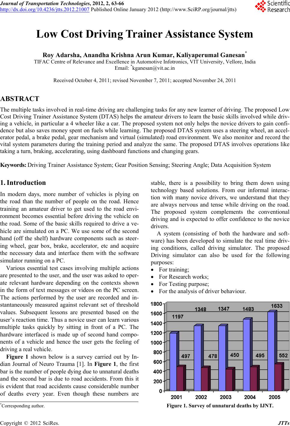
Figure 4. The task evaluation model.
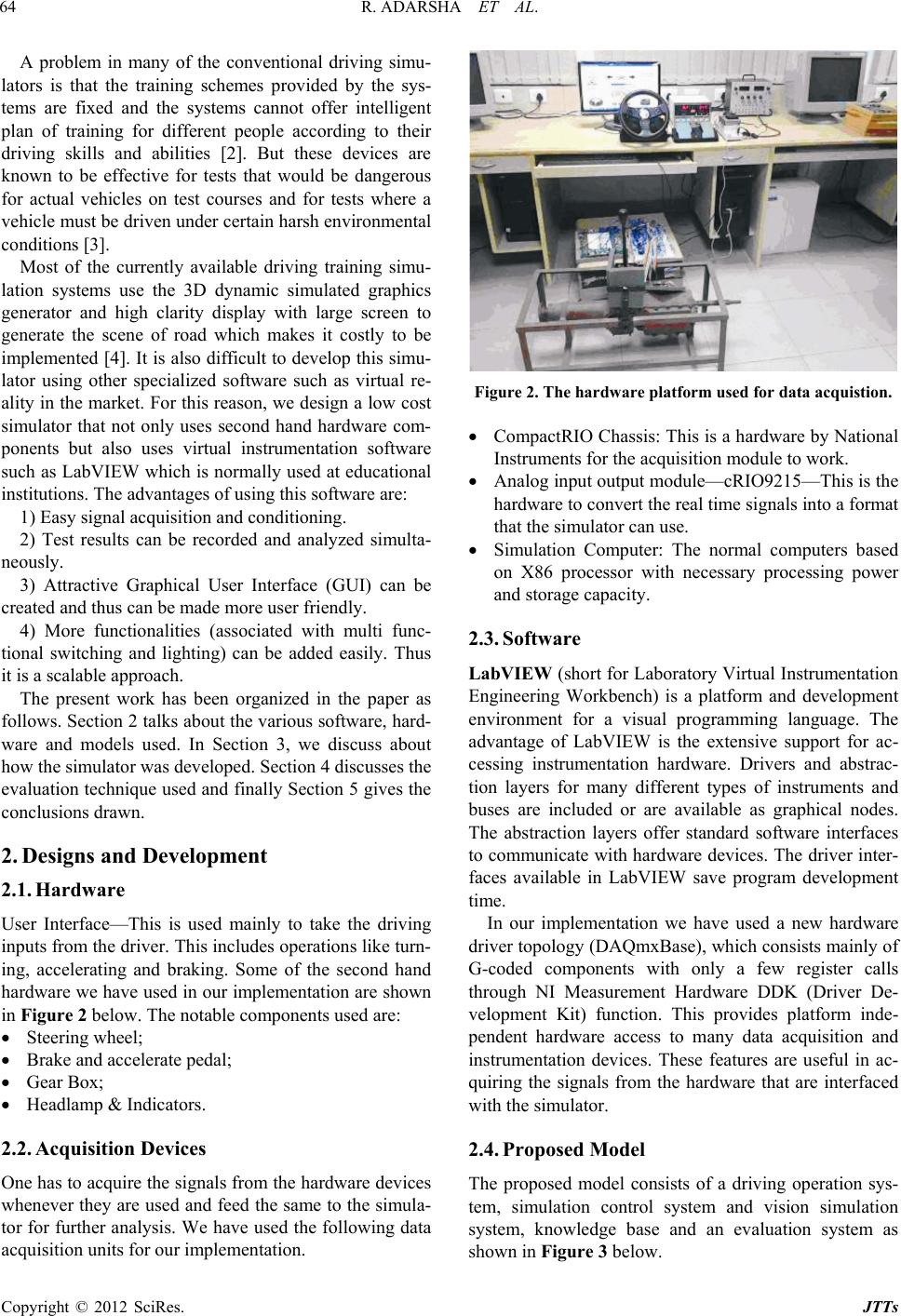
Figure 5. GUI design used in one of the training modules.
based on the various inputs like steering position, gear
position, brake pedal pressure, accelerator pedal pressure,
etc. The brake and accelerator pressure are evaluated
together by calculating the speed using the Equation (1).
Along with th ese, the sequen ce of operations is also eva-
luated here. For example, to take a turn one has to reduce
the speed by braking, shifting gears and then steering to
turn.
4) Visual Interface: This part enables the driver to see
the road condition s as if there is a cockpit in a car. Video
data base has been used. Depending on various circum-
stances the driver has to act within certain time limit as
decided by the timi ng pa rt .
5) Timing part: For each task, the learner has to do the
tasks depending on the road conditions shown to him. A
standard reaction time is set for evaluating the reaction
time of the driver.
4. Evaluation Techniques and Trainer
Also, multiple tasks with parallel data acquisition is de-
signed to test the driver concentration on each of the ve-
hicle controls. This is done by evaluating the tasks and in
parallel running another while loop for data acquisition.
n Ambassador car gear box is taken and an array of
infrared sensor system is deployed to check the gear po-
sition for the evalua tion of the correct gear position for a
given speed [5]. In the proposed trainer system, speed is
taken as the reference signal while th e steering angle and
the gear position data are used for evaluation purpose.
5. Conclusion
There are many commercially available DTAS in the
market. But most of them are very expensive. An attempt
is made to design a low-cost driver trainer assistance
system. The hardware peripherals used are second hand
(used) ones. The software made is to run on a general
purpose common PC to reduce the cost further. One can
add more modules (both hardware and software) and
scale the same if new driving rules emerge. It can be
customized according to people and region. A user gets a
real time feeling and also can learn as much as he wants
without spending on fuel costs. The logged information
is useful for evaluating the drivers. The proposed system
complements the conventional driving.
6. Acknowledgements
This work forms part of the Research and Development
activities of TIFAC-CORE in Automotive Infotronics,
VIT University, and Vellore, India. The authors would
like to thank the Centre for providing necessary hardware
and software support. Adarsh Roy and Arun Kumar
would like to acknowledge Miss. Shalini, Development
Engineer and Mr. Saravanan, Development Engineer for
the help rendered.
REFERENCES
[1] A. Kumar, S. Lalwani, D. Agrawal and R. Rautji, “Fatal
Road Traffic Accidents and Their Relationship with Head
Injuries: An Epidemiological Survey of Five Years,” In-
dian Journal of Neurotrauma, Vol. 5, No. 2, 2008, pp.
63-67.
[2] A. Auckland, J. Manning, et al., “Advanced Driver As-
sistance Systems: Objective and Subjective Performance
Evaluation,” Vehicle System Dynamics, Vol. 46, Supple-
ment 1, 2008, pp. 883-897.
doi:10.1080/00423110802037131
[3] J. Q. Wang, S. B. Li, X. Y. Huang and K. Q. Li, “A Driv-
ing Simulation Platform Applied to Develop Driver As-
sistance Systems,” IEEE Vehicle Power and Propulsion
Conference, Dearborn, 7-10 September 2009, pp. 878-883.
doi:10.1109/VPPC.2009.528975 5
[4] J. Fan and L. R. Xiong, et al., “Intelligent Driving Train-
ing Simulation System Based on Virtual Reality,” Pro-
ceedings of IEEE Intelligent Transportation Systems, Vol.
1, 2003, pp. 27-30.
[5] K. Ganesan and P. S. Babu, “Sensor Based Gear Position
Identification System,” The Journal of the Instrument So-
ciety of India, Vol. 41, No. 3, 2011, pp. 158-160.
A