Circuits and Systems
Vol.07 No.10(2016), Article ID:69782,20 pages
10.4236/cs.2016.710256
A SRF-PLL Control Scheme for DVR to Achieve Grid Synchronization and PQ Issues Mitigation in PV Fed Grid Connected System
Saritha Natesan, Jamuna Venkatesan
Electrical and Electronics Engineering, Jerusalem College of Engineering, Chennai, India
![]()
Copyright © 2016 by authors and Scientific Research Publishing Inc.
This work is licensed under the Creative Commons Attribution International License (CC BY).
http://creativecommons.org/licenses/by/4.0/


Received 18 April 2016; accepted 5 May 2016; published 16 August 2016
ABSTRACT
This paper presents the Synchronous Reference Frame Theory (SRF) based Phase Locked Loop (PLL) to enhance the performance of Dynamic Voltage Controller (DVR). In a grid connected power conversion system, a critical component is the Phase-Locked Loop (PLL) that generates the grid voltage’s frequency and phase angle for the grid synchronization. For grid voltage control, accurate and fast responding PLLs are required to provide phase angle and frequency measurements of the grid voltage. Therefore, SRF based PLL is presented in this work and it calculates the phase angle accurately and effectively. This paper also presents a novel feedback mechanism for SRF-PLL which uses the estimated frequency and phase to achieve grid control. The fundamental signal of the grid voltage is extracted by low pass filter and a unit value controller to generate a unity sine reference signal for the feedback network. In particular, the performance of the SRF-PLL in the three-phase PV fed grid connected system is analyzed under the different power quality issues such as voltage sag and swell. In addition, a detailed study on synchronous reference frame theory is presented. An appropriate control algorithm for DVR is developed and the validity of the proposed configuration is verified through MATLAB simulation results as well as experimental results under different operating conditions.
Keywords:
Photovoltaic (PV), Multi-Level Inverter, Total Harmonic Distortion (THD), Power Quality, dq Frame

1. Introduction
The increasing energy demands of today’s world have increased the usage of renewable energy resources, such as photovoltaic (PV) and wind for electricity power generation [1] . Since power generated by a PV source is primarily DC voltage, it requires a conversion of DC to AC for grid-connected operation. For DC to AC power conversion, multi-level inverter is the prominent choice due to its various advantages over conventional inverters [2] . Its primary function is to enhance the injected active power and to maintain the Total Harmonics Distortion (THD) within IEEE standard. With the increased penetration of sensitive loads and non-linear power electronic loads, the power quality in the modern distribution system has affected in various ways [3] . Major power quality issues in the grid connected system are voltage sags, swells, and faults. Various custom power devices are used to maintain uninterrupted voltage at load terminals. Among different custom power devices, Dynamic Voltage Restorer (DVR) is considered as the most effective solution for above mentioned power quality issues [4] .
Power factor control is an important task in grid-connected systems [5] . By achieving the unity power factor control, accurate phase information of the grid voltage can be detected [6] . For this reason, many Phase Locked-Loop (PLL) control methods had been analyzed in the past decades. The basic PLL concept was initially published by Appleton in 1923 and Bellescize in 1932 to synchronize the two different radio signals with different frequency [6] . In olden days, PLL techniques were widely used in various industrial fields such as communication systems [6] , motor control systems [7] , induction heating power supplies [8] and contactless power supplies [9] . In recent years, PLL techniques are widely used for synchronization between grid connected inverters and the utility network.
For grid synchronization, tracking of phase angle is necessary. The process of phase tracking can be divided into two groups [9] such as open-loop methods and closed loop methods. Some examples of open loop methods are low pass filters, space vector filters or extended Kalman filters. These methods can directly estimate the phase angle of the PCC voltage from its stationery reference variables (alpha and beta coordinates) which is Clarke transformation [9] . In closed-loop methods, PLL is considered as the main example. In PLL methods, its objective is to track the real value of the phase angle. In PLL, the phase angle estimation automatically updated by a closed loop mechanism [10] . However, this method is having some drawbacks such as they are not operating properly under imbalance, harmonic distortion or frequency variations. To overcome these drawbacks, new types of PLL have been developed in recent years. They are Adaptive PLL [10] , Enhanced PLL [11] and SRF-PLL [11] . The main objectives of these three types of PLLs are frequency adaptation and unaffected robust response under voltage and current harmonics or imbalance in the input signals. However, these methods can be used for three-phase power conversion system under power quality disturbances. The control stage of this system is very complicated and hence requires heavy computation stages [12] .
An earlier version of PLL is Zero Crossing Detector (ZCD), where the zero-crossings are detected by capturing the rising or falling edges of the square-wave signals [13] . To obtain the phase control, the phase difference between two input signals is extracted. The main advantage of zero-crossing-based PLL is that it can be easily implemented, but it fails when the synchronization signals have multi zero-crossings due to its harmonics or noises. Another disadvantage of ZCD is that it has poor dynamic response due to one cycle or half cycle control [13] . To overcome these drawbacks, three-phase Synchronous Reference Frame (SRF) based PLL systems are implemented and their phase control performances are better when compared with other types of PLL. This type of PLL can provide the fast and accurate synchronization information with a high degree of immunity and insensitivity to various power quality problems such as power quality disturbances, harmonics, unbalances, voltage sags and swells and notches.
To achieve grid synchronization, the information about instantaneous phase angle and frequency is obtained by time basis PLL technique. To obtain the maximum performance, quality of PLL has to be improved. Grid synchronization is done by locking the phase angle of the grid voltage measured at the Point of Common Coupling (PCC), which is highly distorted due to voltage imbalance, harmonic, and phase or frequency variations with the inverter voltage. In PLL, it is very essential to design and develop a controller very accurately. Because this controller provides fast time response, zero error in the steady state and validity under any input signal for the PLL. The simplest controller used to achieve these parameters is Proportional Integral (PI) controller. The PI controller can be designed in continuous time or discrete-time domain [14] . The regulator gains for PI controller could be calculated through different control strategies such as symmetrical optimum [14] , Wiener optimization, second order system pattern [14] , etc.
The paper is structured as follows. In the first section, introduction about the proposed work is given. Section 2 discusses about the structure of proposed system with SRF-PLL. In section 3, Synchronous Reference Frame theory is explained with its equations and also design of PI controller used in the SRF-PLL system is explained very well. Finally the simulation results of overall PV fed grid connected system with SRF-PLL is shown and explained clearly in section 4. And also, grid synchronization of the PV fed grid connected system under amplitude variation and frequency variations is explained. This section also shows the performance analysis of multi- level inverter and different types of PLL. Section 5 illustrates the experimental setup and results of DVR system for voltage sag and swell compensation.
In this paper, an effort has been made to implement the PLL for grid synchronization under voltage sag and swell condition. And also, various multi-level inverters are designed and simulated. These are used to interface the power generated by PV array to utility grid. Different power quality issues (voltage sag and voltages well) are generated and compensated using DVR. A novel contribution of this work is to introduce SRF-PLL for DVR control circuit to achieve grid synchronization. In order to achieve the grid synchronization, output current of inverter used in DVR operation is considered as one set of input signal and grid voltages are considered as another set of input signals and PLL circuit is implemented.
2. System Description
The proposed PV fed power conversion system with SRF-PLL is shown in Figure 1. It consists of PV array; three-phase Multi-Level Inverter (MLI), DVR and SRF- Phase Locked Loop block. The entire system is connected to the grid at the Point of Common Coupling (PCC). In standalone PV based applications; the major drawback is intermittent power output. This can be overcome by implementing power control with the help of SRF controller. Therefore a constant power supply can be supplied by the PV system. In this proposed system, a three-phase MLI is used. The inverter used in the DVR is operated in current control mode. Because it is very important to operate an inverter in current control mode when it is connected to the grid [15] . Since, the Total Harmonic Distortion (THD) of inverter output voltage is maintained within the IEEE standards, it is the prominent choice of inverter for grid integration. In the case of MLI, sinusoidal PWM technique (multicarrier modulation topology) is implemented to generate the gate pulses for the switching devices used in the inverter.
In this working model, DVR control action is done by SRF-theory based PLL. The basic principle of this theory is transformation of current variables in synchronously rotating d-q frame. To generate the unit vectors,

Figure 1. SRF based PLL for DVR control unit.
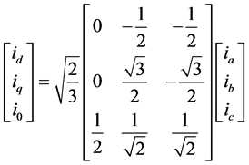
voltage signals are processed by the PLL [15] . As per SRF theory, current signals (abc variables) are transformed into d-q frame and then filtered. Then compensating current variables are transformed from dq frame back to a-b-c frame and fed to current controller which is used for generating switching pulses for inverter switches. In this method, first the source current variables (ia, ib, ic) are carefully detected and then transformed into two-phase stationary frame (α-β-0) from the three-phase stationary frame (a-b-c). This transformation equation is given in Equation (1).
 (1)
(1)
To obtain the dq current components, the two phase current variables iα and iβ of stationary αβ axes are transformed into two-phase synchronous (or rotating) frame (d-q axes) and it is given in Equation (2).
 (2)
(2)
In the above equation, the quantities cosθ and sinθ represents the synchronous unit vectors. It can be generated using the PLL block. In the above equation, the d-q current components are generated and it consists of AC and DC quantities. The fundamental component of current is mentioned by the fixed DC part and the harmonic component is represented by AC part [15] . The current variable id is a combination of active fundamental current component (id DC) and the load harmonic current (ih).
Synchronous reference frame theory states that, the fundamental component of current rotates in synchronism with the rotating frame and therefore it can be considered as DC. By filtering id current variable, the fundamental component of the load current in the synchronous frame can be obtained. By subtracting id dc part from the total d-axis current (id), the AC component id can be produced and it leaves behind the harmonic component of load current. To transform the d-q current variables into α-β variables, inverse transformation is performed and it is given in Equation (3).
 (3)
(3)
According to SRF theory, two phase stationary frame αβ0 current variables are transformed back into three-phase stationary frame abc variables. And also the reference currents are obtained from the following Equation (4). The term Tabc is denoted by transformation function and it is shown in Equation (5).
![]() (4)
(4)
![]() (5)
(5)
By solving the above equations, reference currents are obtained and given in Equation (6). This equation represents the final calculation for transforming abc variables into dq variables.
![]() (6)
(6)
For grid connected applications, the voltage control can also be implemented using synchronous reference frame technique in the same way of current control method as explained above. In this control method, the grid voltage and currents are transformed from their three-phase quantities (abc variables) into a two phase quantities (dq variables) using Clarke transformation function. Since the variables are now rotating synchronously with the reference frame, the control variables can be converted into DC variables [15] . This transformation makes the use of PI controllers to achieve the current control. The real and reactive power flow depends on the d axis and q axis component of voltage and current [15] . This facilitates individual control of real and reactive power flow. The three-phase current quantities (abc variables) of DVR side inverter are converted into two phase quantities (d and q) and PLL implementation is performed.
In this system, the major role of PLL is to track the phase angle required for abc to dq transformation. It is also used for grid synchronization. The main advantage of this proposed SRF-PLL based DVR system is that continuous power supply is suppliedtotheloadbytheactiveconversionofDCvariablestoACvariables.The most popularly used synchronization technique is VCO based PLL as shown in Figure 2. In this method, the difference between phase angle of the input and that of the output signal is measured by the Phase Detection (PD) and passed through the Loop Filter (LF). The LF output signal drives the Voltage-Controlled Oscillator (VCO) to generate the output signal, which will follow the input signal (Vi) [15] .
3. Synchronous Reference Frame Theory Based PLL
Ingrid-connected renewable system, control algorithm plays a vital role and it allows the synchronization between the renewable energy source and the utility grid [16] .Generally all the synchronization algorithms are used to detect the phase of the three-phase utility grid voltages with optimal dynamic response. For proper inverter control operation, detection of the phase angle is very important task [16] .
There are several methods to estimate the phase angle of grid voltage in order to obtain the synchronization of the inverter voltage with the three-phase grid voltages. For grid synchronization, different types of synchronization methods are used. They are Synchronous Reference Frame PLL (SRF-PLL), Positive Sequence Detector based dq PLL (PSD-dq PLL), Dual Second Order Generalized Integrator Phase- Lock Loop (DSOGI-PLL), and Multiple Second Order Generalized Integrator Frequency-Lock Loop (MSOGI-FLL) [16] . All the techniques mentioned above have their own advantages and disadvantages.
Among the various control techniques, SRF-PLL is very effective control technique. All these techniques might be used in different renewable energy applications and the choice of control method will depend on the grid interfacing requirements and regulations to be fulfilled. To implement the control strategy, it becomes necessary to calculate the reference current [17] . Different control strategies are used for the calculation of reference currents namely Instantaneous Reactive Power Theory (p-q theory), Unity Power Factor method, One Cycle Control, Fast Fourier Technique etc. [17] . In this proposed system, SRF theory is used to extract the three- phase reference currents![]() .
.
As already mentioned, a PLL is a closed loop system in which voltage controlled oscillator is controlled to
![]()
Figure 2. Basic block diagram of VCO based PLL.
keep the time and phase of an external periodical signal using a feedback loop [18] . The performance of the control loop is directly affected by the quality of the phase lock. Some common issues faced by power electronic equipment when they are interfacing with the electric grid are, line notching, voltage unbalance, line dips, phase loss and frequency variations [18] . The PLL should be able to reject these sources of error and maintain the accurate phase lock to the grid voltage. In three-phase systems, three-phase time varying quantities are represented by Equation (7).
![]() (7)
(7)
To convert three-phase quantities into rotating reference frame, the first step is to transform the three-phase quantities into an orthogonal component system (alpha and beta) by taking the projections of the three-phase quantities on an orthogonal axis as shown in Figure 3.
This conversion process is known is called the Clarke transform and it is shown in Equation (8). The alpha - beta components are known as stationary reference frame variables.
![]() (8)
(8)
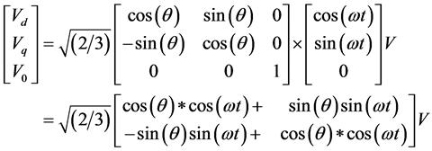
In the stationary reference frame, the net voltage vector makes an angle θ with the orthogonal reference frame and rotates at a frequency of ω. The system can then be reduced to DC by taking the projection of the stationary reference frame components on the rotating reference frame [18] . This is called the Park transform and it is given in Equation (9).
![]() (9)
(9)
In three-phase system, the major role of the PLL is to accurately estimate the phase angle difference between input and output waveforms. The angle estimated by PLL is assumed as θ and the actual angle is assumed as ω * t [18] . The transformation from abc to dq0 variables can be written using Equation (7) and Equation (9).
![]()
Figure 3. Transformation of three-phase voltage variables into stationary rotating reference frame.
![]() (10)
(10)
 (11)
(11)
Using the trigonometric identities, the above Equation (11) can be reduced to,
 (12)
(12)
When the angle traced by PLL is close to the actual voltage vector angle,  is small or close to zero then
  [18] . Therefore, it can be observed that for a balanced three-phase system, the q-axis component in the rotating reference frame reduces to zero when PLL is locked, and it has small error when it is not locked [18] .
 (13)
(13)
This property is used in the Synchronous Reference Frame PLL for three-phase grid connected application. The three-phase quantities are transformed into the rotating reference frame and the q component is used as the phase detected value [19] . A low pass filter or PI controller is then used to eliminate steady state error and the output is fed back to a VCO, which generates the angle and sine values. The block diagram of SRF based PLL for three-phase system is shown in Figure 4. From Equation (13), it is observed that, any error in the phase angle lock process will show up on the q term and that the relation between the error for small values is linear as shown in the Equation (14).
 (14)
(14)
3.1. Transfer Function of PLL
To solve the transfer function of PLL, small signal analysis is done using the network theory and the PLL transfer function can be expressed as follows:
 The closed loop phase transfer function for PLL is given as
Figure 4. SRF based PLL for three-phase system (based on stationary reference frame).
 (15)
(15)
The closed loop error transfer function for PLL is given as,
 (16)
(16)
This closed loop transfer function can be compared with the second order system transfer function and system transfer function can be expressed by,

In the above equation, ωn is the natural frequency and  is the damping ratio of the PLL. These two parameters can be solved by, comparing the system transfer function with the closed loop phase transfer function,
 (17)
(17)
 (18)
(18)
3.2. Discrete Implementation of PI Controller
In the design of SRF-PLL, designing the values of PI controller (also known as loop filter) is very important. The output equation of PI controller is expressed in Equation (19).
 (19)
(19)
Using z transform, Equation (19) can be re-written as:

 (20)
(20)
By using bilinear transformation,
Replace 
In the above equation, T is considered as sampling time. And transfer function of PI controller is rewritten as,

The already obtained Equation (8) and Equation (9) can be compared to map the value of proportional gain and integral gain of the PI controller into the digital domain. It is known that the step response to a general second order equation of H(S) is given by,
 (21)
(21)
By assuming settling time (settling time is defined as the time it takes for the response to settle between an errorband) value of 20 ms and error band of 5%, damping ratio and natural frequency can be obtained. The designed parameters of PI controller are shown in Table 1.
In Table 1 B0 and B1 are called as digital filter coefficients and its values are obtained by substituting Kp and Ki values in the below equation.
 (22)
(22)
 (23)
(23)
In the Equation (22) and Equation (23) is the run rate of PLL and its values is chosen as 10 KHz, B0 and B1 values are obtained by using the above equations.
4. Simulation Results and Discussion
In this section, the simulation of three-phase PV fed grid connected system is shown. And also, voltage sag and swell issues are generated. They are compensated by DVR operation. DVR control unit is implemented with the help of SRF based PLL. Therefore, in addition with the voltage sag and swell compensation, grid synchronization is also achieved with this DVR control action.
4.1. Voltage Sag and Swell Compensation Using SRF-PLL Based DVR
Before generating the voltage sag and swell, the grid connected system is developed and implemented as shown in Figure 5. It consists of PV array model, multi-level inverter, three-phase transformer, non-linear loads and grid. Typically, a PV cell generates a voltage around 0.5 to 0.8 volts depending on the semi-conductor and the built-up technology [19] . This voltage is low enough as it cannot be of use. Therefore, to get benefit from this technology, multiples of PV cells (involving 36 to 72 cells) are connected in series to form a PV module [19] . These modules can be interconnected in series and/or parallel to form a PV panel. In case these modules are connected in series, their voltages are added with the same current [19] .
Since the voltage generated from PV array is DC quantity, to convert the DC into AC quantity, inverter is required before interfacing with the grid. Normally voltage source inverters are used for interconnection. But in this proposed system, multi-level inverter is chosen due to their several advantages over conventional inverters. Their advantages are reduced switching frequency, output voltage with very low distortion and reduced dv/dt stress [20] . Therefore the output of multi- level inverter is connected to three-phase grid via a transformer. The main utility grids are equivalent to AC power and the source impedance connected in series with the grid. In this system, the three-phase grid voltage is 420 V/50Hz and the switching frequency of the inverter is selected as 10 kHz. Voltage sag and swell conditions are generated by connecting additional non-linear loads to the grid. The designed parameters of a grid connected system are shown in Table 2.
4.2. Control of DVR-VSI
In the proposed DVR model, three-phase voltage source inverter is implemented and it is responsible for compensation of voltage sags and swells. It is connected in series to the grid with the help of injection transformer.

Table 1. Designed parameters of PI controller.

Figure 5. Three-phase grid connected system with SRF-PLL based DVR.
Table 2. Designed parameters of grid connected system.
The inverter system consists of an Insulated Gate Bipolar Transistor (IGBT) module, its gate-driver, and an isolation transformer. To control the series inverter, various methods are presented in the literature, to provide dynamic voltage restoration and most of the methods are injecting a voltage in quadrature with advanced phase, so that reactive power is utilized in voltage restoration [20] . But the major drawback of phase advanced voltage restoration techniques are complex in implementation, drop in active power [21] . To overcome these drawbacks, voltages can be injected in-phase with the system voltage during voltage sag or a swell event. Therefore, SRF-PLL control method is implemented for this purpose. In this control method PLL is used to estimate the phase angle θ. Based on the estimated phase angle value, and the line-line grid voltage value, Vab, Vbc, and Vca are transformed into the d-q variables.
Then, these voltages are normalized to unit sine waves using line-neutral system voltage of 120 Vrms. This value is considered as reference value (Vref) and it is compared to with actual system voltages (Vs). Based on this value, the amount of injected voltage is calculated to maintain a constant voltage at the load terminals. Therefore whenever voltage sag or swell is occurred in the grid side, a corresponding voltage is injected (Vinj) in-phase by the DVR to retain a constant voltage (VL) at the load end.
4.3. Analysis of Multi Level Inverter for Grid Connected Systems
In this system, three-phase grid is fed by multi-level inverter. With the use of sine PWM modulation scheme, Total Harmonic Distortion (THD) value of inverter can be reduced without any additional control technique. This technique can eliminate the choice of large filter inductor and capacitance [22] . Initially, seven-level inverter was designed with multi carrier modulation strategy and it is simulated. It is found that, the THD value of seven-level inverter is very high 13.72%. But as per IEEE standard of voltage harmonics (IEEE-519-Voltage Distortion Limits), the maximum allowed THD value should be 5% only. Therefore to meet the power quality standard, various levels of inverter are designed and simulated. The fundamental voltage of various levels of an inverter is shown in Figure 6. To know the performance of multi-level inverters, different THD values of multi-level inverter are shown in Figure 7.
When additional loads are connected to the grid, grid voltage is severely affected by voltage sag and swell problem. These two major issues are mitigated by DVR. It act as voltage controller and whenever grid voltage is reduced or increased from its nominal range, the change in voltage is detected by DVR, and required amount of voltage is injected by DVR for that entire period of PQ problem. To provide three-phase controllable voltage source, it uses Voltage Source Inverter (VSI).The performance of grid connected system is analyzed under the condition of sag and swell problem. In this system, 30% of decrease in voltage is initiated from the time period
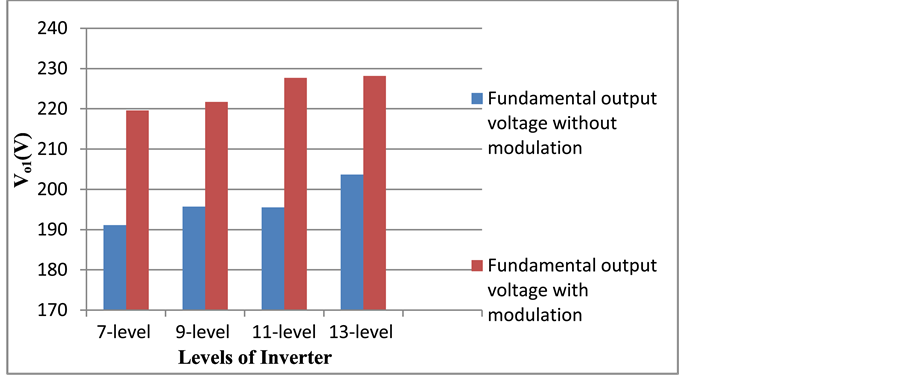
Figure 6. Comparison of fundamental output voltages of multi-level inverter.

Figure 7. Comparison of percentage of THD of multi-level inverters.
of 0.2 sec to 0.3 sec and 50% of increase in voltage is initiated from the time period of 0.5 sec to 0.6 sec. The disturbed grid voltage and current is shown in Figure 8.
To compensate the load voltage, DVR is designed and interconnected with the grid connected system. DVR is a series connected power electronics based device that can quickly mitigate the voltage sag and swell in the system and restore the load voltage. In this system, 30% of decrease in voltage is initiated for 5 cycles (from 0.2 to 0.3 sec) at the PCC as shown in Figure 9(a). And also 50% of increase in voltage is initiated for 5 cycles (from 0.5 to 0.6 sec). To correct the sag or swell voltage, the decrease or increase in voltage is detected by DVR and it is compared with the three-phase reference voltage signal (shown in the control block of DVR). By comparing this voltage with a reference voltage (reference voltage is same as that of actual source voltage under normal conditions), triggering pulses can be generated. These pulses are given to the switches of Voltage Source Inverter (VSI) block used in DVR system.
By the action of inverter used in DVR, required phase voltage will pass through the injection transformer to mitigate the sag voltage. This injection process will be done continuously unless and until the load voltage meets the rated voltage. The injected voltage required to compensate the voltage sag (Figure 9(b)). The output voltage after compensation by the proposed DVR model is shown in Figure 9(c).
4.4. Grid Synchronization Using SRF-PLL
To analyse the performance of SRF-PLL, the same grid connected circuit is implemented with SRF-PLL as

Figure 8. Grid voltage and current with 30% decrease in voltage and 50% increase in voltage.

Figure 9. Voltage sag and swell mitigation by DVR: (a) Grid voltage under decrease and increase in voltage condition; (b) Injected voltage by DVR; (c) Compensated voltage by DVR action.
shown in Figure 10. When harmonic distortion of the input signal occurs or the wide frequency range, the accurate phase information cannot be obtained by the conventional PLL methods [23] . Based on the conventional methods and their problems above, a new SRF-PLL method for three-phase grid connected inverter systems is developed to solve the problems.
The MATLAB/Simulink model of three-phase SRF-PLL is shown in Figure 10. Initially, the grid voltages (Va, Vb and Vc) are multiplied with inverter current variables (Ia, Ib and Ic). In this model, multipliers serve as phase detectors. If the phase difference between two signals is zero degree, then the error signal is zero, which represents the locked state of the PLL. If there is any phase difference, non-zero error signal is produced and it is said to be unlocked state [24] . Next, three-phase voltage signals Va, Vb and Vc are transferred from three phases to a stationary system of two phases Vd and Vq as presented in Figure 11. These Vd and Vq variables are separated into qe and de variables. A low pass filter is designed and it is used to extract the fundamental signal from the grid voltage as a unity sine reference. This sine reference signal is obtained from qe conversion block to sin-cos signal generations block as shown in Figure 12. This sin-cos signal is fed back to the conversion block, so that to lock the frequency and phase angle between inverter and grid voltage. The dynamic and static performances are verified by simulation results.
In this PLL circuit, the function of PI regulator is to track the phase when the grid frequencies are changed below or above the rated frequency. Initially, the phase angle θ is estimated with θ*. The parameter θ*is the integral value of the estimated frequency ω*. The estimated frequency ω* is the sum of the PI controller output and the feed forward frequency ωf. By using this value and following the Equation (11), gain of the PI-regulator is designed so that estimated frequency ω* is locked on the system frequency ω.
The performance of the proposed SRF- PLL with the injection of 5th and 7th order harmonic contents into the grid voltage is given in Figure 13. Although periodic disturbance with two times the fundamental frequency is also introduced in the system, the proposed SRF- PLL system achieves accurate phase-locked control within 2.4 cycles. From the simulation results it is clearly observed that, when 5th and 7th order harmonics injection to grid voltage, the phase angle is locked very well.
The performance of PLL is analyzed for various frequency values and the results are obtained. When the grid voltage frequency reduces from 50 to 40 Hz at 0.05 s, PLL tracks the phase angle correctly and maintain the

Figure 10. Subsystem of SRF-PLL system.

Figure 11. Subsystem of qd to qe and de conversion.

Figure 12. Subsystem of qe and de signal to sin-cos conversion.
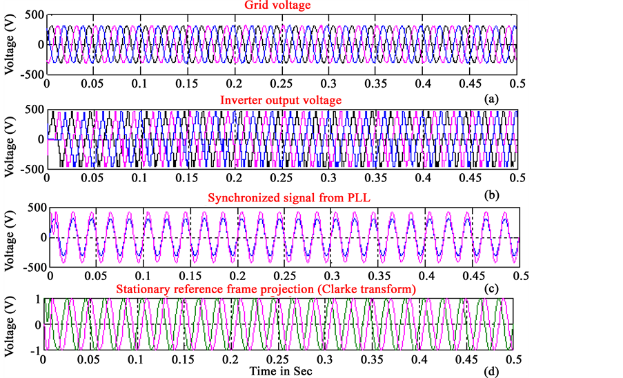
Figure 13. Phase locked performances: (a) Three-phase grid voltage signal with the frequency of 50 Hz; (b) Multi-level inverter output voltage; (c) Phase locked process when grid voltage is 50 HZ; (d) Generation of stationary reference frame variables.
synchronism between inverter and grid voltage. The performance of the SRF-PLL under this condition is presented in Figure 14(a). It indicates that the less static error is caused between the grid voltage and the output voltage of inverter when the frequency jumps. In this phase locked process, phase angle of both signals are locked with the settling time of 2.4 cycles.
It is seen from Figure 14(b), even if the system operates at the frequency lesser than the rated frequency of 50 Hz (i.e. 45 Hz), PLL works effectively. The phase locked process with 50 Hz of grid frequency is shown in Figure 14(c). Phase locked process with 55 Hz of grid frequency is shown in Figure 14(d). The response of PLL with 60 Hz of frequency is shown in Figure 14(e). From these simulation results, it is observed that, the system could easily track the phase when the frequency was changed to frequency below and above the rated frequency. In a practical grid connected system, frequency variations are of much smaller magnitude. The only difference from the ideal condition and practical condition is that the PI-regulator now approaches the value of 2 × π × 5 instead of zero value.
In this system, 5th and 7th order harmonics are added to the input signal. The designed PLL is working effectively even at the harmonic injection and the phase angle of the fundamental frequency is tracked accurately.The whole system is designed to deliver the power of 4000 W to the load. With the SRF-PLL system, grid active power is maintained as 4300 W during the operation and grid reactive power is obtained as 2000 VAR. The grid active and reactive power with PLL system is shown in Figure 15.
In this work, SRF-PLL has been developed to achieve the grid synchronization under various frequency ranges. The PLL presented in this method is based on trigonometric function transformation and synchronous reference frame theory. The filter used in the PLL is easy to design and implement. And also, 13-level inverter is simulated and connected to grid to supply the power to the grid. Simulation results verify that this type of SRF-PLL method has good phase locked control under wide frequency tracking range when compared with conventional types of PLL methods. To know the performance of SRF-PLL, its results are compared other types of PLLs such as pPLL, Park PLL and Digital PLL. The performance parameters of different PLL methods are shown in Table 3. When compared with all other types of PLL methods, SRF-PLL takes short settling time under all frequency change in condition as shown in Figure 16.
When the grid frequency changes, static error caused is only 3 degrees, but this error is small and all the settling time is shorter compared with other methods. And also, when third order and seventh order harmonics are introduced in the grid voltage this type of PLL can obtain the accurate phase locked control. Because in SRF-PLL method, the low pass filter is correctly designed and implemented to reduce the effect of harmonics in the system.
5. Experimental Results and Discussion
In order to verify the theoretical concept and above simulation results experimentally, a hardware prototype of the complete single phase DVR system was constructed and is shown in Figure 17. It consists of a switch, an inverter circuit, injection transformer, controller circuit, and their power supply circuit. To record the data, Digital Storage Oscilloscope (DS-1022C) is used. The simulations results are validated by real-time testing of the DVR circuit. Here, voltage sag is generated by connecting heavy loads to the DVR circuit. The power supply circuit provides the necessary 5V for microcontroller and 12 V for driver IC IR2110. In addition this 5 V supply is also given to trigger the op to coupler of driver IC IR2110. External crystal of 4 MHz is used to speed up the operation of PIC microcontroller. A suitable coding is written using MPLAB and the same is burnt using Pickit2. Coding for generations of pulses is derived from the modes of operation. A suitable dead band is given in order to prevent short circuiting of Switches. The generated pulses are amplified using IR2110 driver IC. The high and low side driver output is correspondingly given to upper and lower switches of power circuit.
In this circuit model, load experiences voltage sag of 10% magnitude for 0.5 ms duration as shown in Figure 18. From this waveform, it can be observed that, after 0.5 ms the load voltage is reduces and this continues during the entire circuit operation. This sag voltage will be compensated by injecting the required amount of voltage through the injection transformer.
Whenever DVR detects voltage sag or swell, it must inject the required amount of voltage properly to the load. When DVR is activated, magnitude of load voltage remains constant due to the injected voltage, which increases during the voltage sag event to compensate for the voltage sag. The compensated voltage by DVR action is shown in Figure 19. From the waveform, it is observed that, after 0.5 ms, load maintains the same amount of

Figure 14. Phase locked performances: (a) Start up process of SRF-PLL when the frequency of grid voltage is 40 Hz; (b) Phase locked process when the grid voltage suddenly changes from 40 Hz to 45 Hz; (c) PLL response when the frequency varies from 45 Hz to 50 Hz; (d) PLL response when the frequency changes from 50 to 55 Hz; (e) PLL response when the frequency changes from 55 Hz to 80 Hz.

Figure 15. Grid active and reactive power with PLL.
Table 3. Performance comparison of different PLL methods.

Figure 16. Performance analysis of various PLL methods.
voltage. Therefore, from DVR experimental waveforms, it can be concluded that the designed DVR system hardware setup is able to respond instantaneously to compensate voltage sags.
6. Conclusions
In this paper, the concept of Synchronous Reference Frame Theory based PLL is explained. This PLL control strategy is implemented to the DVR system to improve its voltage restoration capabilities. With this integration

Figure 17. Experimental setup of DVR model.

Figure 18. Uncompensated load voltage.

Figure 19. Compensated load voltage with DVR action.
of PLL, the DVR will be able to independently compensate voltage sags and swells without requiring any additional controller. Design of major components used in PLL circuit is explained. Experimental setup of the single phase DVR system is presented and the ability to provide temporary voltage sag compensation is tested. In addition with the voltage sag and swell compensation, grid synchronization is also achieved effectively for various frequency ranges such as 40 Hz, 45 Hz, 50 Hz, 55 Hz and 60 Hz. In this work, SRF-PLL method has been presented based on synchronous reference frame theory. The filter used in the method is easy to design and implement. With this designed PLL system, phase angle is accurately tracked within acceptable margins. The settling time and static errors for different PLLs are compared and analyzed very well. It is observed that, this SRF-PLL method has good dynamic and static performances under the wide frequency range. Moreover it has the good and accurate phase angle tracking control with wide frequency range. Therefore this type of PLL system with the PI-regulator can be operated in a real life application.
In the future, the proposed SRF-PLL method can be applied for DVR when symmetrical and asymmetrical faults are generated in distributed power generation system to achieve the grid control and synchronization.
Cite this paper
Saritha Natesan,Jamuna Venkatesan, (2016) A SRF-PLL Control Scheme for DVR to Achieve Grid Synchronization and PQ Issues Mitigation in PV Fed Grid Connected System. Circuits and Systems,07,2996-3015. doi: 10.4236/cs.2016.710256
References
- 1. Gupta, A., Chanana, S. and Thakur, T. (2015) Power Quality Assessment of a Solar Photovoltaic Two-Stage Grid Connected System: Using Fuzzy and Proportional Integral Controlled Dynamic Voltage Restorer Approach. Journal of Renewable and Sustainable Energy, 7, 231-238.
http://dx.doi.org/10.1063/1.4906980 - 2. Rahim, N.A., Chaniago, K. and Selvaraj, J. (2011) Single-Phase Seven-Level Grid-Connected Inverter for Photovoltaic System. IEEE Transactions on Power Electronics, 58, 540-549.
http://dx.doi.org/10.1109/tie.2010.2064278 - 3. Safari, A. and Mekhilef, S. (2011) Simulation and Hardware Implementation of Incremental Conductance MPPT with Direct Control Method Using Cuk Converter. IEEE Transactions on Industrial Electronics, 58, 1154-1161.
- 4. Somayajula, D. and Grow, M.L. (2015) An Integrated Dynamic Voltage Restorer-Ultra Capacitor Design for Improving Power Quality of the Distribution Grid. IEEE Transactions on Sustainable Energy, 6, 616-624.
http://dx.doi.org/10.1109/TSTE.2015.2402221 - 5. Blaabjerg, F., Teodorescu, R., Liserre, M. and Timbus, A.V. (2013) Overview of Control and Grid Synchronization for Distributed Power Generation Systems. IEEE Transactions on Industrial Electronics, 53, 1398-1409.
http://dx.doi.org/10.1109/TIE.2006.881997 - 6. Chatterjee, A., Keyhani, A. and Kapoor, D. (2011) Identification of Photovoltaic Source Models. IEEE Transactions on Energy Conversion, 26, 883-889.
http://dx.doi.org/10.1109/TEC.2011.2159268 - 7. Ding, K., Bian, X.G., Liu, H.H. and Peng, T. (2012) A MATLAB-Simulink-Based PV Module Model and Its Application under Conditions of Non-Uniform Irradiance. IEEE Transactions on Energy Conversion, 27, 864-872.
http://dx.doi.org/10.1109/TEC.2012.2216529 - 8. Zhang, Q., Sun, X.-D., Zhong, Y.-R., Matsui, M. and Ren, B.-Y. (2011) Analysis and Design of a Digital Phase- Locked Loop for Single-Phase Grid-Connected Power Conversion Systems. IEEE Transactions on Industrial Electronics, 58, 3581-3591.
http://dx.doi.org/10.1109/TIE.2010.2087295 - 9. El-Naggar, K. and Abdelhamid, T.H. (2008) Selective Harmonic Elimination of New Family of Multilevel Inverters Using Genetic Algorithms. Energy Conversion and Management, 49, 89-95.
http://dx.doi.org/10.1016/j.enconman.2007.05.014 - 10. Ebrahimi, J., Babaei, E. and Gharehpetian, G. (2011) A New Topology of Cascaded Multi-Level Converters with Reduced Number of Components for High Voltage Application. IEEE Transactions on Power Electronics, 26, 3109-3118.
http://dx.doi.org/10.1109/TPEL.2011.2148177 - 11. Kabir, M.N., Mishra, M., Ledwich, G., Dong, Z.Y. and Wong, K.P. (2012) Coordinated Control of Grid-Connected Photovoltaic Reactive Power and Battery Energy Storage Systems to Improve the Voltage Profile of a Residential Distribution Feeder. IEEE Transactions on Industrial Informatics, 10, 967-977.
http://dx.doi.org/10.1109/TII.2014.2299336 - 12. Kanjiya, P., Singh, B., Chandra, A. and Al-Haddad, K. (2013) “SRF Theory Revisited” to Control Self-Supported Dynamic Voltage Restorer (DVR) for Unbalanced and Nonlinear Loads. IEEE Transactions on Industry Applications, 49, 2330-2340.
http://dx.doi.org/10.1109/TIA.2013.2261273 - 13. Adhikari, S. and Li, F.X. (2014) Coordinated V-f and P-Q Control of Solar Photovoltaic Generators with MPPT and Battery Storage in Microgrids. IEEE Transactions on Smart Grid, 5, 1270-1281.
http://dx.doi.org/10.1109/TSG.2014.2301157 - 14. Balamurugan, K., Srinivasan, D. and Reindl, T. (2012) Impact of Distributed Generation on Power Distribution Systems. Energy Procedia, 25, 93-100.
http://dx.doi.org/10.1016/j.egypro.2012.07.013 - 15. Che, L., Amirahmad, A., Zhan, Q., Kutkut, N. and Batarseh, I. (2014) Design and Implementation of Three-Phase Two-Stage Grid-Connected Module Integrated Converter. IEEE Transactions on Power Electronics, 29, 3881-3892.
http://dx.doi.org/10.1109/TPEL.2013.2294933 - 16. Al-Omari, Z. (2014) Influence of Control Modes of Grid-Connected Solar Photovoltaic Generation on Grid Power Flow. Engineering, 6, 914-922.
http://dx.doi.org/10.4236/eng.2014.613083 - 17. Perez, M.A., Espinoza, J.R., Moran, L.A., Torres, M.A. and Araya, E.A. (2008) A Robust Phase-Locked Loop Algorithm to Synchronize Static Power Converters with Polluted AC System. IEEE Transactions on Industrial Electronics, 55, 2185-2192.
http://dx.doi.org/10.1109/TIE.2008.918638 - 18. Karimi-Ghartemani, M., Karimi, H. and Iravani, M.R. (2004) A Magnitude/Phase-Locked Loop System Based on Estimation of Frequency and In-Phase/Quadrature-Phase Amplitudes. EEE Transactions on Industrial Electronics, 51, 511-517.
http://dx.doi.org/10.1109/TIE.2004.825282 - 19. Eltawil, M.A. and Zhao, Z. (2010) Grid-Connected Photovoltaic Power Systems: Technical and Potential Problems. Renewable and Sustainable Energy Reviews, 14, 112-129.
http://dx.doi.org/10.1016/j.rser.2009.07.015 - 20. Jovcic, D. (2003) Phase Locked Loop System for FACTS. IEEE Transactions on Power Systems, 18, 1116-1124.
http://dx.doi.org/10.1109/TPWRS.2003.814885 - 21. Lavopa, E., Zanchetta, P., Sumner, M. and Cupertino, F. (2009) Real-Time Estimation of Fundamental Frequency and Harmonics for Active Shunt Power Filters in Aircraft Electrical Systems. IEEE Transactions on Industrial Electronics, 56, 2875-2884.
http://dx.doi.org/10.1109/TIE.2009.2015292 - 22. Jian, L.N., Bai, H., Zhao, W.X. and Liang, J.N. (2015) Electrification and Renewable Energy Generation. The Scientific World Journal, 2015, Article ID: 275238.
http://dx.doi.org/10.1155/2015/275238 - 23. Singh, B. and Arya, S.R. (2013) Implementation of Single-Phase Enhanced Phase-Locked Loop-Based Control Algorithm for Three-Phase DSTATCOM. IEEE Transactions on Power Delivery, 28, 1516-1524.
- 24. Rauf, A.M. and Khadkikar, V. (2015) Integrated Photovoltaic and Dynamic Voltage Restorer System Configuration. IEEE Transactions on Sustainable Energy, 6, 400-410.
http://dx.doi.org/10.1109/TSTE.2014.2381291