Advances in Chemical Engineering and Science
Vol.05 No.03(2015), Article ID:58371,18 pages
10.4236/aces.2015.53040
Radiative Heat Transfer and Thermocapillary Effects on the Structure of the Flow during Czochralski Growth of Oxide Crystals
Reza Faiez*, Yazdan Rezaei
Solid State Lasers Department, Laser & Optics Research School, Tehran, Iran
Email: *rfaiez@gmail.com
Copyright © 2015 by authors and Scientific Research Publishing Inc.
This work is licensed under the Creative Commons Attribution International License (CC BY).
http://creativecommons.org/licenses/by/4.0/


Received 22 June 2015; accepted 24 July 2015; published 28 July 2015
ABSTRACT
A numerical study was carried out to describe the flow field structure of an oxide melt under 1) the effect of internal radiation through the melt (and the crystal), and 2) the impact of surface tension-driven forces during Czochralski growth process. Throughout the present Finite Volume Method calculations, the melt is a Boussinnesq fluid of Prandtl number 4.69 and the flow is assumed to be in a steady, axisymmetric state. Particular attention is paid to an undulating structure of buoyancy-driven flow that appears in optically thick oxide melts and persists over against forced convection flow caused by the externally imposed rotation of the crystal. In a such wavy pattern of the flow, particularly for a relatively higher Rayleigh number , a small secondary vortex appears nearby the crucible bottom. The structure of the vortex which has been observed experimentally is studied in some details. The present model analysis discloses that, though both of the mechanisms 1) and 2) end up in smearing out the undulating structure of the flow, the effect of thermocapillary forces on the flow pattern is distinguishably different. It is shown that for a given dynamic Bond number, the behavior of the melt is largely modified. The transition corresponds to a jump discontinuity in the magnitude of the flow stream function.
Keywords:
Numerical Simulation, Fluid Flow, Radiative Heat Transfer, Thermocapillary Forces, Czochralski Method, Oxides

1. Introduction
Refractory oxide crystals such as gadolinium gallium garnet (GGG) and yttrium aluminum garnet (YAG) are widely used as solid-state laser hosts and materials for epitaxial films in magneto-optical devices [1] [2] . As the most commonly used technique, garnet crystals are grown by Czochralski (Cz) method mainly characterized by hydrodynamics of the melt which is inextricably coupled to transport phenomena in this configuration. Motions relevant to the Cz melt can be classified by the principal of driven forces into the following main groups: 1) gravitational (natural convection), 2) mechanical (forced convection) and 3) surface tension (Marangoni convection). These different kinds of the melt motion are quite complex and their intensity and interaction determine the flow structure, the heat and mass transport, the shape of crystal/melt interface and consequently the quality of the crystal [3] . Defect formation in the crystal as well as spiral growth of oxides are strongly influenced by convective flow and its instabilities [4] - [6] .
Accounting for the internal radiation within the melt and crystal is of crucial importance in numerical modeling of Cz growth of oxides because they are often semitransparent to infrared radiation [7] [8] . Radiative heat transfer (RHT) strongly couples with the melt dynamic and, as demonstrated by Xiao and Derby [9] , considerably affects the interface shape. Their model, however, approximated the internal radiation through the crystal being totally transparent and so could not be provide an explanation of the effect of optical properties of the crystal. Furthermore, the melt was assumed to be opaque and consequently did not participate in the radiative heat transfer in the model.
Tsukada et al. [10] have developed a global analysis of heat transfer in the Cz oxide growth system in which the influence of the optical properties of both the melt and the crystal on the interface morphology has been studied. In their model, however, forced convection flow and thermocapillary effect was neglected. Recently, much progress has been made in understanding the effect of internal radiation on the thermal convective pattern generated at the melt free surface for which the Marangoni instability is an indispensable factor [10] [11] . Jing et al. [12] have numerically revealed that when the internal radiation was ignored, a spoke pattern was generated and the bulk melt flow was oscillatory; the pattern disappeared when the melt assumed to be semitransparent. These computational efforts were generally based on three-dimensional modeling of Cz oxide melt in an open crucible and consequently all effects attributed to the crystal, including its optical properties, were ignored. More recently, Budenkova et al. [13] have reported the results of a two dimensional, axisymmetric modeling of the Cz growth of Gd3Ga5O12(GGG) and Tb3Ga5O12(TGG) crystals. In contrast to GGG, the authors in [13] concluded that the heat transfer in TGG can be described within the model of opaque crystal of thermal conductivity in the range 3.5 - 5.0 W∙m−1∙K−1. For both of the cases, the melt was assumed to be opaque, and the thermocapillary effect as well as the meniscus influence on the crystal/melt interface was ignored.
In this paper, we report the results of a numerical simulation of the Czochralski growth of a large-diameter GGG crystal. The main subject of the present model calculations is, in a first step, to explain the effect of internal radiation on the flow and thermal fields. The results obtained for semitransparent material are compared with the case in which both the melt and the crystal are assumed to be opaque to the thermal radiation. The convective behavior of the melt is discussed, and it is shown that the thermal stratification of the fluid depends on the intensity of buoyant forces in optically thick melt. The undulating pattern of the thermal field disappears with contribution of the internal radiation in heat transfer in the melt. Throughout the first step, thermocapillary flow is neglected.
In the second step, the material is assumed to be opaque, and the radiative heat exchange occurs between exposed surfaces in the Cz enclosure. The structure and properties of a small vortex which appears in the melt of high Rayleigh number is studied. It is shown that there is a critical thermocapillary coefficient at which the undulating structure [14] of the flow and, consequently the small vortex near the crucible bottom disappears. The transition of the flow pattern corresponds to a jump discontinuity in the magnitude of the flow stream function.
2. Model Description
The Cz growth system can be characterized by coexisting vertical and horizontal temperature gradients and the differential rotation rates of the crystal and crucible. The general feature of the fluids motion in the Cz crucible is described as follows. The buoyancy-driven hot flow ascends along the crucible wall and then accompanied by the surface/tension-driven flow, travels along the melt free surface towards the crystal rim. The fluid is being cooled down along the path and more intensively adjacent to the crystal/melt interface (CMI) due to the larger heat conductivity of the oxide crystal. This creates a stream of cold fluid which descends along the centerline towards the crucible bottom. If the crucible is at rest and the crystal rotation rate is sufficiently low, the flow is essentially buoyancy driven with a unicellular meridional circulation, namely the Hadley cell circulation [15] , with a small zonal flow driven by the crystal rotation. The crystal rotation drives a flow which streams upward below the crystal, outward along the meniscus, and down along the boundary between the Hadlay cell circulation and the forced convection cell. The shear layer between the buoyancy and rotationally driven cells, known as a Stewartson layer [16] , is characteristic of rotating fluids. Considerable effort has expended to ensure that, depending on the Rayleigh number, the flow in a side-heated cavity similar to Cz melt, displays two-dimen- sional axisymmetric behavior. As well, it is believed that secondary vortices which appear in the convective flow of high Rayleigh number cannot be attributed to an instability of base flow but are a direct consequence of convective distortion of the thermal field [17] .
In the model, the crystal pulling rate is, as usual, much smaller than the characteristic velocity of the buoyancy-driven flow. Therefore, the system is assumed to be in a quasi-steady state. In the melt model, the fluid motion is substantially determined by the natural convection for which the Rayleigh number does not exceed the relevant critical value estimated for relatively high Prandtl number fluids [17] [18] . Therefore, the assumption of axisymmetric transport processes in the melt can be justified. Furthermore, the significant mechanisms of instability in Cz melt model arise because of the non-linear interaction of rotational and buoyant flows to which the temperature field is strongly coupled. Therefore, axisymmetric behavior is expected for the melt model without an intense swirl.
In the present modeling of Cz-oxide growth process with bulk radiation incorporated in the governing equations, the influence of thermal convections on the flow pattern is studied. The externally imposed rotational effect is, however, assumed to be secondary in the present analysis. The crystal rotation, when accounted for in the melt, breeds a small zonal flow beneath the CMI. For experimentally reasonable rates of rotation, the flow pattern remains almost unchanged.
2.1. Physical Model
The schematic in Figure 1(a) illustrates that the configuration adopted in the present analysis consists of a crucible of radius  and height
 , the oxide melt of height
 , the cylindrical shape crystal of curved shoulder and with dimensions
  and
and , the ambient gas and enclosure of height
  and radius
 . The
. The

 (a) (b)
Figure 1. (a) Schematic diagram of the Czochralski growth configuration; (b) non-uniform finite differential mesh used for calculations.
melt aspect ratio  is equal to unity and the ratio of radii
 . Corresponding to the crystal volume,
  is a reasonable height of crucible expose wall. Because the meniscus configuration at the crystal edge directly affects the contact area between the fluid and the crystal, its influence is taken into account in the numerical simulation. As shown in Figure 1(a), some of this area is almost vertical and consequently allows for radial heat transfer (both convective and radiative) from the melt to the surrounding near the CMI. In the vicinity of the crucible wall, however, a right angle contact is assumed.
The mathematical model developed here, incorporates transport process in the melt and the crystal. In the ambient gas phase, assumed to be totally transparent to the thermal radiation, only the energy equation is solved. The semitransparent phases are bounded to diffuse-gray surfaces and, according to the spectroscopic measurements of the refractory oxides optical properties [19] , the optical thickness of the melt is taken to be larger than that of the crystal. For most of the calculations performed here, the thermophysical properties of GGG, reported just recently by IKZ-Berlin [20] , are employed. The physical properties of the two phases of the Cz domain are given in Table 1. For theoretical purpose, however, two parameters ( and
and ) are allowed to take different values within a reasonable range of data reported for oxides. The geometrical and growth parameters used in the present study are listed in Table 2. The common non-dimensional groups which characterize the melt behavior in the Cz/GGG configuration are given and compared with those of YAG in Table 3.

Table 1. Thermophysical properties, including optical data [20] , employed in calculation; the subscripts l, x, a, c and k denote melt, crystal, air, crucible and insulating enclosure, respectively.
e: Estimated values.
Table 2. Geometrical and process parameters used for calculations.
Table 3. Dimensionless parameters of the garnet oxide GGG and YAG melts for the same characteristic length  and temperature difference
  as described in Table 2. All thermophysical properties are taken from the IKZ-report [20] .
  is the melt Prandtl number.
  is the Stefan-Boltzmann constant.
2.2. Basic Assumption
The fluid flow for the melt region is described by coupled Navier-stokes and heat equations. The present model involves the following assumption: 1) the melt is an incompressible Newtonian fluid which satisfies the Boussinesq approximation; 2) the fluid flow is laminar; 3) viscous dissipation is negligible; 4) the melt/gas interface is not calculated from the Young-Laplace equation, but instead, following Galazka et al. [21] , an appropriate curvature of the melt free surface has been assumed so that, it provides the melt meniscus at the crystal rim; 5) the constant angle is equal to the equilibrium growth angle of the garnet crystals; 6) the crucible bottom is thermally insulated and its side walls are at a uniform and constant temperature, ; 7) the top enclosing wall is at the same temperature as the ambient
 ; 8) above the crucible top end, the temperature of the insulating enclosure wall varies in the range
 ; 9) no-slip condition is applied for all physical boundaries except for the melt free surface. The free surface is considered to be free of stresses or not according to the cases in which the thermocapillary effect is taken into account. Throughout this work the temperatures
 ,
,  and
and , as well as the temperature difference
  are the same for all cases.
To estimate the contribution of the internal radiation to heat transfer in the melt, the crystal and melt are assumed to be absorbing/emitting mediums bounded by vanishingly thin semitransparent diffuse gray surfaces. As a disposal parameter [7] [10] the optical thickness of the melt,  is assumed to be significantly larger than that of crystal
 . In second step of the calculations, both the crystal and melt are supposed being opaque
  mediums. Throughout the present modeling, the ambient gas phase does not participate in the radiative heat transport, that is, its optical thickness
  is equal to zero. The refractive index of the gas phase is
 , and it is assumed that
  as given in Table 1. The crucible wall and its bottom wall, as well as the insulating enclosure walls are diffuse and opaque gray surfaces.
3. Numerical Approach
A finite volume method (FVM) is applied to compute quasi-steady and axisymmetric solutions to the fully coupled equations governing heat transfer and melt hydrodynamics for Czochralski growth of garnet oxide GGG crystal. The radiative heat transfer strongly couples with fluid dynamics [7] - [10] . Therefore, an accurate modeling of the Cz/GGG configuration requires a simultaneous solution of the radiative transfer equation and the fluid dynamics equations. This means that numerical procedure used for the radiative transfer must be compatible with the transport equations for other processes. During the last decade, different methods have been developed to solve the radiative transfer equation for refractory oxides growth systems. The PN-approximation which expands the radiation intensity by an orthogonal series of spherical harmonics [22] is widely used in its simplest form, i.e. the P1-approximation. Numerically, it has been shown, however, that the computational methods based on the P1-approximation is valid only for optically thick materials [23] . This means that with increasing the contribution of internal radiation to heat transfer, or decreasing the conduction/radiation ratio  in the melt and/or the crystal, the P1-approximation is not of course a suitable approach. Furthermore, the approximation may be substantially in error for multi-dimensional systems with large aspect ratios and/or when surface emission dominates over medium emission [22] [23] .
As given in Table 3, the Planck number of garnet oxide melts is low  [24] and the radiative heat transfer is the dominant mechanism in the participating mediums. As well, for Cz/oxide configuration, the melt surface emission has usually an important contribution to heat transport in the system. The disadvantages of the P1-approximation are removed by the use of discrete ordinates (DO) method based on a discrete representation of the angular dependence of the radiation intensity. The DO method has been widely recognized to be one of the most appropriate methods in high-temperature applications such as Cz/oxide growth system. This is particularly because the DO method shares the same philosophy and computational grid as the fluid dynamics approach [24] [25] . In the present modeling the DO method was applied to describe the major influence of the internal radiation transfer on the flow and thermal fields in the Cz/GGG configuration. The DO method does not demand any assumption concerning the angular variation in the radiation intensity. The working equations of the method are written in a finite difference form and total integration over the solid angle is performed using numerical quadratures.
3.1. Governing Equations
The equations describing the conservation of mass, momentum and energy for the two-dimensional (2D) model represented and restricted in the preceding sections, are expressed as follows.
 (1)
(1)
 (2)
(2)
 (3a)
(3a)
where ,
,  , and
, and  are the melt velocity vector, pressure, and temperature respectively. In addition to conduction and convection, thermal energy is transferred in the melt by radiation as described by the last term of Equation (3a). Within the crystal Equation (3a) takes the following form.
 (3b)
(3b)
To estimate the radiative heat flux , the radiative transfer equation must be solved.
We consider the radiative heat transfer for the axisymmetric system (the melt and crystal) depicted in Figure 2. Based on the DO method, the balance of energy passing in a specified direction  through a small differential volume in an emitting-absorbing, but not scattering, gray medium can be expressed by the following equation,
 (4)
(4)
where ,
,  and
and  are the direction cosines and
  is the intensity of radiation for a discrete direction
 . The subscript i represents the melt
  and/or the crystal
 .
.  is the angle of revolution around the z-axis, and
  is the intensity of black-body radiation at the temperature of the medium. The radiative heat flux,
  which appeared in Equations (3a) and (3b), can be written as follows,
 (5)
(5)
where  is the angular quadrature in the direction
  which sums to the surface area of a unit sphere,
  is the unit normal vector and the index, m is used to sum over all directions. Each octant of the angular space
  at any spatial location is discretized into
  solid angels of extend
 . In this calculation we have used,
  and
and .
.
In the present work, the optical properties on both sides of the semitransparent mediums (the crystal and the melt) surfaces are estimated with their refractive indices [26] [27] ,  , as follows,
 (6a)
(6a)
 (6b)
(6b)
where  and
and  are the transmissivity of the crystal and/or the melt surface for the externally and internally incident radiations, respectively, and
  stands for reflectivity of the surface. The emissivity
  is neglected in the case of semitransparent surfaces.
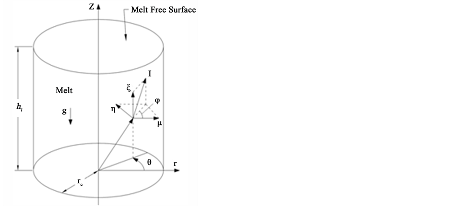
Figure 2. Coordinate system used.
In the Cz configuration Figure 1(a), each material constituting the system, such as the melt, the crystal and the crucible expose wall, is surrounded by a transparent gas, and the incident radiative heat flux to their surfaces through the ambient gas, is partially absorbed and reflected but not transmitted if the material is opaque. In this case, the emissivity of the melt into the ambient phase can be estimated as , and the emissivity into the crystal is 1.0 if
  as assumed in the model.
3.2. Boundary Conditions
The velocity boundary conditions are  for all boundaries except for,
o the melt free surface where boundary conditions can be expressed by components as
 (7a)
(7a)
if thermocapillary convection is taken into account ;
;
o at the crystal walls and the crystal/melt interface
 (7b)
(7b)
o at the melt centerline
 (7c)
(7c)
For any variable  of the model,
  is equal to zero by symmetry. The boundary conditions for temperature and radiative intensity can be written as follows when the melt and the crystal are both semitransparent. The convective effect of the ambient gas is ignored.
o At the melt free surface:
 (8a)
(8a)
 (8b)
(8b)
 (8c)
(8c)
o at the sidewall of the crystal:
 (9a)
(9a)
 (9b)
(9b)
 (9c)
(9c)
o at the crystal/melt interface:
 (10a)
(10a)
 (10b)
(10b)
o at the insulating enclosure wall:
 (11a)
(11a)
 (11b)
(11b)
o at the top enclosing surface:
 (12a)
(12a)
 (12b)
(12b)
o at the crucible submerged wall:
 (13a)
(13a)
 (13b)
(13b)
o at the crucible bottom:
 (14a)
(14a)
 (14b)
(14b)
o at the exposed portion of crucible wall:
 (15a)
(15a)
 (15b)
(15b)
o at the centerline:
 (16a)
(16a)
 (16b)
(16b)
where subscripts ,
,  denote the outgoing and incoming directions relative to boundary surface, respectively. The energy balance at the crystal/melt interface is described by Equation (10) in which no radiative transfer term appears because the interface does not have any volume. It has been shown that both the meniscus configuration [28] and the crystal top surface shape [29] affect the Cz/oxide growth process. To take into account the effect of meniscus formation (Figure 1(a)) on both convective and radiative transfer, the boundary conditions for the melt free surface, including Equations (8b) and (8c), should be slightly modified.
The governing equations with boundary conditions for the fluid flow and heat transport in the system were numerically solved by employing control volume (CV) based finite differential technique. The SIMPLEC algorithm [30] was used to couple velocities and pressure on staggered grids, and second order upwind method was used for discretization of momentum and energy equations. The equations are integrated over each CV and the resulting system of algebraic equations is solved iteratively until convergence is reached. Figure 1(b) provides a sample of non uniform mesh layout used in the present simulations. The cell number for both the melt and the
crystal sums up 13,806 (each with area ) and for the gas phase consist of 2435 CV with
 . The system consist at most a total of 82836 mathematical unknowns. For all variables
 , the solution is deemed convergent when the criterion
  was satisfied where n denotes the index of iteration.
4. Results
The present section is divided into two parts: 1) the results which explain the effect of internal radiation transfer on the convective flow and thermal fields in the melt dominated by the buoyancy forces the intensity of which is respected by the Rayleigh number Ra, and 2) the results which reveal the influence of thermocapillary forces on the convective pattern in the melt when the material does not participate in the radiative heat transport. For the cases in which the internal radiation is ignored the boundary conditions for temperature and radiative transfer between the exposed opaque surfaces, are expressed as given in reference [12] . The reliability and accuracy of the present simulation was ascertained by validating the general results of calculations with numerical results of the convection in the Cz/oxide melt [8] [9] . Comparison was made with the results obtained by Hintz et al. [28] [31] for a Cz melt (Pr = 6.8) simulated in a model experiment. The present numerical results were found to be in a good agreement with the results in literature for opaque and/or semitransparent Cz/oxide melts.
The convective behavior of GGG melt in the model can be characterized by the dimensionless similarity parameters given and compared to YAG melt in Table 3. However, to investigate 1) the effect of internal radiation on the buoyancy-driven flow, and 2) the influence of Marangoni convection on the flow field pattern, calcula-
tions were carried out for opaque system with  and
and  and
and  (corresponding to different values of
  ).
).
4.1. The First-Step Results 
The numerical simulations of the opaque  and the semitransparent
  systems are comparatively shown in Figures 3(a)-(c) for the melt in which the intensity of natural convection is given by
 . With respect to the symmetry axis, the right and the left part of each figure in the series of simulations correspond to the computations with (case C1) and without (case C2) the internal radiation, respectively. This comparative representation of the variables for optically different mediums (C1 and C2) in each figure, disclose rapidly the effect of internal radiation on the flow and thermal fields. Quantitatively, the simulation results are elucidated in Table 4, where the range of Rayleigh number surveyed is
 .
.
Stratification of the Melt and Radiative Heat Transport
It is well known [32] [33] that for an incompressible fluid, buoyancy forces can give rise to internal gravity waves if the fluid is a stratified medium. According to linear theory, instability of a shear flow can only occur if the Richardson number,  is less than 1/4 somewhere in the flow [15] . For a Boussinesq fluid, the appropriate
form of the non dimensional parameter is given by  where
where  stands for the buoyancy frequency defined as
 . Thus, the local Richardson number [32] is proportional to the ratio
 . Consequently, the velocity gradient must be sufficiently strong before the instability occurs. The condition
  everywhere happens to be both necessary and sufficient for stability of flow [32] .
Table 4. Flow velocity components (mm/s) and the magnitude of  for the melt model of
 , and
, and  under the optical conditions C1 and C2.
 (a) (b) (c)
Figure 3. Flow pattern (a), temperature distribution (b) and velocity field (c) in the opaque (left) and semitransparent (right) melt . For details see Table 4,
 .
.
As shown in Figure 3(b), the optically thick melt is a thermally stratified medium. The effect of optical properties on the flow pattern is shown in Figure 3(a). The comparative simulation of the melt behavior describes that, in contrast to the semitransparent melt, the opaque melt exhibits an undulating structure near the crucible bottom due to a retarding force caused by vertical stratification of the fluid. Within the surveyed range of
 , thermal stratification increases with
 , and the undulating is enhanced so that a small secondary vortex appears near the bottom for
 . As shown later (Figure 4(a) and Figure 4(b)) in the opaque melt of
  the temperature gradient around the vortex position are
  and
and  (40% larger), and the local frequency of the waves in this position is estimated to be
 .
.
Figure 3(c) shows how large the internal radiative transfer affects the velocity field pattern. Though the components of the field, with the exception of  located on the symmetry axis, are increased (see Table 4), the velocity gradient is considerably decrease in the semitransparent (case C1) melt. In the other words, compared to the opaque system (case C2), the velocity field is more largely distributed in the semitransparent
melt (C1). For each value of the Rayleigh number  in Table 4, the streamline function
  is much smaller for the opaque system so that
  is found to be a good approximation. By the use of a new expression the Richardson number [32] [33] in which
 , it is expected that the temperature gradients, particularly in the lower part of the melt, should be
significantly different for two optically distinguished cases C1 and C2. More precisely, it is anticipated that, for opaque melt  should be measurably larger than
 , while for the semitransparent melt, the difference between the radial and axial temperature gradients is smeared out.
To describe the details relevant to the discussion, Figure 4(a) and Figure 4(b) show the temperature variations along the vertical  and horizontal
  lines, both passing the center of the small secondary vortex.
The vortex (named RFV hereafter) appears only in the opaque melt and its center, located at the point  , remains for
 . As well, the approximately elliptical shape of RFV and the ratio of the vortex diameters
  remain almost unchanged for Rayleigh number within the range. However, the vortex is stretched in both directions with Rayleigh numbers and the area,
  , is therefore increased about 18.7% with Ra number changed from
  to
to .
.
 (a) (b)
Figure 4. Temperature variation along the (a) vertical and (b) horizontal lines, including the vortex diameters,  and
and , respectively, for the two optically distinguished melts
 . Temperature gradients around the vortex (RFV) position in opaque system (C2), are
  and
and  (40% larger). For semitransparent melt (C1),
  , the vortex is merged.
Radial velocity profile along the vertical , including the larger diameter
  of the vortex, is shown in
Figure 5 to observe the eventual implication of Rayleigh-Fjørtoft’s necessary (but not sufficient) condition of instability [32] in the opaque melt. The condition is expressed as  somewhere in the flow field, where
  and
and  is a point at which the second derivative of velocity,
  equals to zero. At the intersection point P of the vortex diameters (
 and
and ), the components of the field change the sign; both the lower and the upper edges of the elliptical shape vortex (RFV), that is, the points A and B, respectively, are the inflexion point
 . Along the line
 , from the crucible bottom up to the point B, the negative sign of the profile curvature
  is changed
  and the profile is deemed to satisfy the condition of instability. For the semitransparent melt, the inflexion point on the velocity profile is disappeared. Sufficiently far from the vortex (RFV) in opaque melt, the velocity profile on a vertical line
 , passing the melt mid-point
  and the tri-junction point J (see Figure 1) displays (not shown here) no inflexion point. This would be inferred that the instability in the melt model is located around the point
 .
.
4.2. The Second-Step Results ,
,  ,
, 
This section is assigned to description of 1) the properties of the small secondary vortex (RFV) which appears in the optically thick melt model and 2) the role of thermocapillary forces on the flow field structure which lead to similar results on the fluid motion as the radiative transfer.
In this section, the melt is assumed to be opaque. For the present steady and axisymmetric model, the streamlines are defined in terms of the velocity components as  and
and , all lie in the meridional plane, and the vorticity
  vector is orthogonal to the plane of fluid motion.
4.2.1. Structure and Properties of the Vortex
It has been shown [34] that for two dimensional, steady motion of an incompressible fluid of constant viscosity , vorticity equation reduces to
  which describes the balance between the vortex convection and the diffusion of vorticity. A vortex tube in the flow, is therefore a ring-shaped region of closed streamline,
  with radius
  around the symmetry axis. The vorticity vector
  is tangent to the tube surface
  at every point on the surface, and the vortex lines are said to form the boundary of the vortex tube.
The area of the normal cross-section of the vortex tube is approximated by , and the volume
  of the melt encompassed by the surface
 , is likely given by
 . The ratio
  is independent of the length
  of the vortex tube. It has been

Figure 5. Radial velocity profile along the line  including the vortex larger diameter
 , in opaque melt (case C2) compared with the semitransparent (C1) case for which the instability is suppressed by the stable stratification (
 ,
, and
and ). At the point P,
  , and the points A and B are an inflexion points
  on the profile.
shown [34] that an elliptical patch of uniform vorticity  will rotate with angular velocity
  , and the motion is unstable if ratio of diameters
  is greater than 3 [34] .
For the case ,
,  and
and , Figure 6(a) and Figure 6(b) display that the vortex center,
  at which
 , is characterized by
  and
and . At the points C and D on the closed curve of
 , vorticities have the same magnitude as
  (see Figure 6(b)). However, along the vertical line
 , vorticity decreases from
  to
to  and then vanishes at the point B (see Figure 6(a)). The vortex center, P coinsides an inflexion point. The points A and B on
the boundary,  are close to positions at which
  and
and , respectively. As showed before, temperature gradient between the two points, A and B is
 , and around the closed streamline region,
  is located at the point A while
  at the point B. This can be inferred that at the upper edge of the vortex, the vorticity diffusion
  dominates over the convection of vortex lines.
Contrarily, at the lower edge, around the point A, viscous dissipation has the lowest effect. Note that, vorticity intensification due to stretching of vortex lines, does not occur in the present 2D model.
Within the surveyed range of , the radius of the tube almost unaltered while the normal cross-section
  and consequently the volume
  increase with the Rayleigh number.
Increasing the Rayleigh number, the non-uniformity of the vorticity distribution on the closed  region remains undulated. However, the vorticity is intensified, as expected, for the cases of of stronger boundary-driven
flow (not shown here) and, as shown in Figure 7, the ratio  is decreased with the melt Grashof number
 . This can be displayed that the ratio
  is also decreasing with
 . One may result that, by increasing the Rayleigh number of the melt, vortex motion becomes more stable and the so-called strength of tube,
  [34] is increased.
4.2.2. Thermocapillary Forces and Vortex Merging
Surface tension gradient,  generates convective flow at the melt free surface. Appropriate scaling of the tangential shear stress balance,
  along the free surface produces the Marangoni number, Ma as defined in Table 3. The Rayleigh-Bénard instability [15] which arises owing to thermal
 (a) (b)
Figure 6. Stream function and vorticity plotted along (a) the vertical and (b) the horizontal lines  and
and , respectively. For
  ,
,  and
and , the vortex center
  is characterized by
  and
and . The closed streamline region,
  has an elliptical shape of
  and, for the points on the boundary
 , while
 .
.

Figure 7. Dependence of geometrical properties of vortex tube on the intensity of buoyancy-driven flow in the melt ( ,
, and
and ).
).  is in cm3.
stratification in the vicinity the melt free, is removed in the presence of thermocapillary flow. The effect, as expected, depends on the intensity of Ma-flow or more precisely, on the ratio of the boundary to surface tension forces represented by  with
with  as a Reynolds number based on the surface tension-in- duced velocity. However, in the interior of melt wherein
 , the ratio is given by [35]
 (17)
(17)
where  and
and  are the magnitudes of stream function when the flow is buoyancy-and/or surface tension- driven, respectively.
To investigate the influence of thermocapillary forces on the flow pattern in the present optically thick melt of  and
and , simulation were carried out for the cases of different surface tension coefficients
 . As shown in Figures 8(a)-(c), the impact of the surface tension-dri-
 (a) (b) (c)
Figure 8. Flow pattern (a), temperature distribution (b) and velocity field (c) in the melt ( ,
, and
and ) for the two cases of
  (left) and
  (right) where
 .
.
ven forces on the melt behavior is significantly different for two cases of  where
where  . In fact, the flow exhibits an undulating structure associated with a small vortex (RFV) for
 , and this wavy structure of the flow is totally modified for
 .
.
In the case with , the thermocapillary forces in the interior of the melt, however, displace the vortex center from the point
  to
to . The vortex center, now located at the point
 , is characterized by
 ,
,  and
and . The elliptical-shape vortex diameters and so the area of normal cross-section area
  are practically unaltered with respect to the case
 . The radius
  of vortex tube
  gets larger and consequently both the surface area
  and the volume
  are now considerably
  increased. Noticeably, in contrast to the case with
 , vorticity at the point
  on the closed streamline region
  does not vanish to zero. It means that, the fluid particles which couldn’t be exchanged between the region
  (with
(with ) of the fluid and any region of non-zero vorticity, now
  participate in the exchange process.
For a negligibly small increment of the thermocapillary forces, that is, for , the main feature of the flow and thermal fields are modified (see Figure 8): the wavy structure of the flow and the vortex (RFV) are both abruptly disappeared. It means that, for a certain value of
 , thermocapillary forces end up in vanishing the vertical stratification of the melt. This sudden change in the melt behavior occurs when
  corresponding to
  in the interior
  of the melt. The same point
  into the present unstratified melt, is characterized by
 ,
,  and
and . Note that, for
 , the flow velocity at the point
  (as the vortex center) was equal to zero and the ratio
  was around 4%. This can be inferred that the fluid encompassed by
  (or
(or , when
 ) was practically at rest. However, by increasing the thermocapillary forces to
 , the energy stored in the thermally stratified melt is then released. The effect is correlated with merging of the vortex and suppression of instability in the melt.
For two cases of , the radial velocity profiles along the vertical line
  passing through the point
  (as well as
  and
and ) are shown in Figure 9. The inflexion point
  which coinsides with the point
  on the curve for
 , disappears for the case
 . As well, Figure 9 displays that, the radial velocity at point
  which is vanished to zero for
 , is significantly changed when
 . These profiles are similar to those displayed in Figure 5 where the effect of the melt optical properties was considered.
Figure 10 displays that, in an optically thick melt of 
 , the magnitude of
  changes abruptly when the intensity of Marangoni flow is enhanced up to a certain

Figure 9. Radial velocity profile along the line  passing through the point
  and including the larger diameter
  of the vortex (RFV) when
 . The inflexion point
  disappears for
 .
. ,
,  and
and .
.

Figure 10. Abrupt change in the magnitude of  for a threshold value of surface tension coefficient
 , in an optically thick melt of
 . The jumps occur at
 .
.
value . The jump in
  correlated with a significant modification of the melt behavior. Within the surveyed range of the Rayleigh number, the effect was found to be stronger for higher Rayleigh number. As well, the thermocapillary forces needed to modify the structure of the flow are stronger for more intensive convective flow. Consequently, the Bond number corresponding to the jump is found to be almost constant
  for the melt of
  and
and .
.
This can be inferred that more energy is stored in the wavy structure of the flow by increasing the Rayleigh number of the melt. The small secondary vortex (RFV) volume  is also increasing with
 . The vortex does not appear for
  while the flow still exhibits an undulating structure due to a retarding force caused by vertical stratification of the melt near the crucible bottom. For
 the vortex (RFV) is formed and its normal cross-section area,
  and consequently [34] the strength Γ of the vortex tube are increased with
 . Remarkable is that, in contrast to the thermocapillary effect, forced convection due to the crystal rotation, even for
  which corresponds with a dramatic change in the crystal/melt interface (not shown here), leaves the wavy pattern and the vortex (RFV) practically unaltered. In the present model, GGG melt is characterized by
 , and while the parameter
  is much smaller than unity, the ratio
  is equal to 2.70 and increases with larger thermal gradients through the system. It means that thermocapillary forces affect more strongly the behavior of the melt than the forced convection. Note that, the ratio
  corresponds to
  for which the jump in magnitude of
  (see Figure 10) occurs.
5. Summary and Conclusions
Two-dimensional axisymmetric simulations of the Navier-stokes equations were used to investigate the behavior of the melt under a) the effect of internal radiative transfer and b) the influence of thermocapillary forces, during Cz growth of GGG crystals.
The results indicated that the two different mechanisms end up, however, in a similar pattern of the flow in the interior of the melt: the undulating structure of the flow, caused by vertical stratification of the melt, was smeared out when the melt assumed to be semitransparent (case C1) and/or when the surface tension coefficient
 exceeded slightly its threshold value
  in the optically thick melt (case C2;
 ).
).
The wavy pattern of the flow found to be enhanced with increasing in the intensity of convective flow  in the melt. It was shown that, the Rayleigh-Fjørtoft’s condition of instability was statisfied for the optically thick melt (case C2) in which more thermal energy is stored in the internal waves. The condition was deemed to be removed in the case C1.
The properties of an elliptical-shape secondary vortex (RFV) which appears in the interior of the opaque melt of , has been received some attention. In the absence of thermocapillary forces
 , the vortex
center , coincided with an inflexion point on the vorticity profile (Figure 6). The cross-section area of the vortex were increased by
 .
.
In the presence of thermocapillary forces , the vortex was impelled towards the point
  in the interior of opaque melt. The structure of the flow in the melt of
  found to be sharply changed when the ratio
  was close to
 . It means that, for a given intensity of buoyancy-driven forces, there exists a corresponding threshold value of
  to which the behavior of the melt is highly sensitive (Figure 8). It was shown that, the effect corresponds with a jump-discontinuity in the magnitude of
  (Figure 10) which occurs at
  where
where  is negligibly small.
Cite this paper
RezaFaiez,YazdanRezaei, (2015) Radiative Heat Transfer and Thermocapillary Effects on the Structure of the Flow during Czochralski Growth of Oxide Crystals. Advances in Chemical Engineering and Science,05,389-407. doi: 10.4236/aces.2015.53040
References
- 1. Fei, Y.T., Chou, M.M.C. and Chai, B.H.T. (2002) Crystal Growth and Morphology of Substituted Gadolinium Gallium Garnet. Journal of Crystal Growth, 240, 185-189.
http://dx.doi.org/10.1016/S0022-0248(02)00876-X - 2. Jia, Z., Tao, X., Dong, C., Cheng, X., Zhang, W., Xu, F. and Jiang, M. (2006) Study on Crystal Growth of Large Size Nd3+: Gd3Ga5O12 (Nd:GGG) by Czchralski Method. Journal of Crystal Growth, 292, 386-390.
http://dx.doi.org/10.1016/j.jcrysgro.2006.04.041 - 3. Polezhaev, V.I. (2003) Modeling of Technically Important Hydrodynamics and Heat/Mass Transfer Processes during Crystal Growth. In: Scheel, H.J. and Fukuda, T., Eds., Crystal Growth Technology, John Wiley, Chichester, 155-186.
http://dx.doi.org/10.1002/0470871687.ch8 - 4. Wilke, H., Crnogorac, N. and Cliffe, K.A. (2007) Numerical Study of Hydrodynamic Instabilities during Growth of Dielectric Crystals from the Melt. Journal of Crystal Growth, 303, 246-249.
http://dx.doi.org/10.1016/j.jcrysgro.2006.10.151 - 5. Uecker, R., Wilke, H., Schlom, D.G., Velickov, B., Reiche, P., Polity, A., Bernhagen, M. and Rossberg, M. (2006) Spiral Formation during Czochralski Growth of Rare-Earth Scandates. Journal of Crystal Growth, 295, 84-91.
http://dx.doi.org/10.1016/j.jcrysgro.2006.07.018 - 6. Lan, C.W. and Tu, C.Y. (2001) Three-Dimensional Simulation of Facet Formation and the Coupled Heat Flow and Segregation in Bridgman Growth of Oxide Crystals. Journal of Crystal Growth, 233, 523-536.
http://dx.doi.org/10.1016/S0022-0248(01)01599-8 - 7. Tsukada, T., Kobayashi, M. and Jing, C.J. (2007) A Global Analysis of Heat Transfer in the CZ Crystal Growth of Oxide: Recent Developments in the Model. Journal of Crystal Growth, 303, 150-155.
http://dx.doi.org/10.1016/j.jcrysgro.2006.11.344 - 8. Tsukada, T., Kobayashi, M., Jing, C.J. and Imaishi, N. (2005) Numerical Simulation of CZ Crystal Growth of Oxide. Fluid Dynamics & Materials Processing, 1, 45-62.
- 9. Xiao, Q. and Derby, J.J. (1994) Heat Transfer and Interface Inversion during the Czochralski Growth of Yttrium Aluminum Garnet and Gadolinium Gallium Garnet. Journal of Crystal Growth, 139, 147-157.
http://dx.doi.org/10.1016/0022-0248(94)90039-6 - 10. Tsukada, T., Kakinoki, K., Hozawa, M. and Imaishi, N. (1995) Effect of Internal Radiation within Crystal and Melt on Czochralski Crystal Growth of Oxide. International Journal of Heat and Mass Transfer, 38, 2707-2714.
http://dx.doi.org/10.1016/0017-9310(95)00077-M - 11. Jing, C.J., Imaishi, N., Sato, T. and Miyazawa, Y. (2000) Three-Dimensional Numerical Simulation of Oxide Melt Flow in Czochralski Configuration. Journal of Crystal Growth, 216, 372-388.
http://dx.doi.org/10.1016/S0022-0248(00)00427-9 - 12. Jing, C.J., Hayashi, A., Kobayashi, M., Tsukada, T., Hozawa, M., Imaishi, N., et al. (2003) Effect of Internal Radiative Heat Transfer on Spoke Pattern on Oxide Melt Surface in Czochralski Crystal Growth. Journal of Crystal Growth, 259, 367-373.
http://dx.doi.org/10.1016/j.jcrysgro.2003.07.033 - 13. Budenkova, O.N., Vasiliev, M.G., Yuferev, V.S., Ivanov, I.A., Bul’kanov, A.M. and Kalaev, V.V. (2008) Investigation of the Variations in the Crystallization Front Shape during Growth of Gadolinium Gallium and Terbium Gallium Crys- tals by the Czochralski Method. Crystallography Reports, 53, 1181-1190.
http://dx.doi.org/10.1134/S106377450807016X - 14. Kobayashi, M., Hagino, T., Tsukada, T. and Hozawa, M. (2002) Effect of Internal Radiative Heat Transfer on Interface Inversion in Czochralski Crystal Growth of Oxides. Journal of Crystal Growth, 235, 258-270.
http://dx.doi.org/10.1016/S0022-0248(01)01786-9 - 15. Ristorcelli, J.R. and Lumley, J.L. (1992) Instabilities, Transition and Turbulence in the Czochralski Crystal Melt. Jour- nal of Crystal Growth, 116, 447-460.
http://dx.doi.org/10.1016/0022-0248(92)90654-2 - 16. Xiao, Q. and Derby, J.J. (1995) Three-Dimensional Melt Flows in Czochralski Oxide Growth: High-Resolution, Massively Parallel, Finite Element Computations. Journal of Crystal Growth, 152, 169-181.
http://dx.doi.org/10.1016/0022-0248(95)00090-9 - 17. Markatos, N.C. and Pericleous, K.A. (1984) Laminar and Turbulent Natural Convection in an Enclosed Cavity. International Journal of Heat and Mass Transfer, 27, 755-772.
http://dx.doi.org/10.1016/0017-9310(84)90145-5 - 18. Jaluria, Y. and Gebhart, B. (1988) Buoyancy Induced Flows and Transport. Hemisphere, Washington DC.
- 19. Kobzev, G.A. and Petrov, V.A. (1993) Measurement of Thermal Radiation and Optical Properties of Refractory Oxi- des and Their Melts under CO2 Laser. Thermochimica Acta, 218, 291-304.
http://dx.doi.org/10.1016/0040-6031(93)80430-I - 20. Crnogorac, N. and Wilke, H. (2009) Measurement of Physical Properties of DyScO3 Melt. Crystal Research and Tech- nology, 44, 581-589.
http://dx.doi.org/10.1002/crat.200800530 - 21. Galazka, Z. and Wilke, H. (2000) Influence of Marangoni Convection on the Floe Pattern in the Melt during Growth of Y3Al5O12 Single Crystals by the Czochralski Method. Journal of Crystal Growth, 216, 389-398.
http://dx.doi.org/10.1016/S0022-0248(00)00426-7 - 22. Modest, M.F. (1993) Radiative Heat Transfer. McGraw-Hill, New York, 487.
- 23. Lan, C.W., Tu, C.Y. and Lee, Y.F. (2003) Effects of Internal Radiation on Heat Flow and Facet Formation in Bridgman Growth of YAG Crystals. International Journal of Heat and Mass Transfer, 46, 1629-1640.
http://dx.doi.org/10.1016/S0017-9310(02)00454-4 - 24. Colomer, G. (2006) Numerical Methods for Radiative Heat Transfer. Diss. PhD Thesis, Universitat Politècnica de Catalunya, Barcelona.
- 25. Liu, J., Shang, H.M. and Chen, Y.S. (2000) Development of Unstructured Radiation Model Applicable for Two-Di- mensional Planar and Three-Dimensional Geometries. Journal of Quantitative Spectroscopy & Radiative Transfer, 66, 17-33.
http://dx.doi.org/10.1016/S0022-4073(99)00162-4 - 26. Spuckler, C.M. and Siegel, R. (1992) Refractive Index Effects on Radiative Behavior of a Heated Absorbing-Emitting Layer. Journal of Thermophysics and Heat Transfer, 6, 596-604.
http://dx.doi.org/10.2514/3.11539 - 27. Spuckler, C.M. and Siegel, R. (1994) Refractive Index and Scattering Effects on Radiation in a Semitransparent Laminated Layer. Journal of Thermophysics and Heat Transfer, 8, 193-201.
http://dx.doi.org/10.2514/3.523 - 28. Hintz, P. and Schwabe, D. (2001) Convection in a Czochralski Crucible—Part 2: Rotating Crystal. Journal of Crystal Growth, 222, 356-364.
http://dx.doi.org/10.1016/S0022-0248(00)00885-X - 29. Nunes, E.M., Naraghi, M.H.N., Zhang, H. and Prasad, V. (2002) A Volume Radiation Heat Transfer Model for Czoch- ralski Crystal Growth Processes. Journal of Crystal Growth, 236, 596-608.
http://dx.doi.org/10.1016/S0022-0248(02)00826-6 - 30. Ferziger, J.H. and Peric, M. (2002) Computational Methods for Fluid Dynamic. Third Edition, Springer, Berlin, 166- 178.
http://dx.doi.org/10.1007/978-3-642-56026-2 - 31. Hintz, P., Schwabe, D. and Wilke, H. (2001) Convection in a Czochralski Crucible—Part 1: Non-Rotating Crystal. Journal of Crystal Growth, 222, 343-355.
http://dx.doi.org/10.1016/S0022-0248(00)00884-8 - 32. Drazin, P.G. and Reid, W.H. (1982) Hydrodynamic Stability. Cambridge University Press, Cambridge, 320-333.
http://dx.doi.org/10.1115/1.3162197 - 33. Fein, J.S. and Pfeffer, R.L. (1976) An Experimental Study of the Effects of Prandtl Number on Thermal Convection in a Rotating, Differentially Heated Cylindrical Annulus of Fluid. Journal of Fluid Mechanics, 75, 81-112.
http://dx.doi.org/10.1017/S002211207600013X - 34. Acheson, D.J. (1994) Elementary Fluid Dynamics. Clarendon Press, Oxford, 162-191.
- 35. Jones, A.D. (1988) Scaling Analysis of the Flow of a Low Pr Number Cz Melt. Journal of Crystal Growth, 88, 465- 476.
http://dx.doi.org/10.1016/0022-0248(88)90145-5
NOTES

*Corresponding author.