Journal of Signal and Information Processing
Vol. 3 No. 3 (2012) , Article ID: 22140 , 10 pages DOI:10.4236/jsip.2012.33053
Roadmap for Establishing Interoperability of Heterogeneous Cellular Network Technologies -2-
![]()
Innov’COM Lab, Higher School of Communications, Sup’Com, University of Carthage, Tunis, Tunisia.
Email: hasni.neji63@laposte.net, ridha.bouallegue@gmail.com
Received May 8th, 2012; revised June 7th, 2012; accepted June 16th, 2012
Keywords: UMTS; Interoperability; Ontology; Feature Modeling; UML
ABSTRACT
The global project will focus on an eventual establishment of a holistic understanding of cellular communication, and proposing an ontological approach that expresses the domain’s concepts, classes, and properties in a formal and unambiguous way. However, this ongoing step is about making heterogeneous network technologies explicit and highlighting their commonalities and variabilities. It begins by studying three different cellular technologies, one from each generation (2G, 3G and 4G). After the analysis of Lte-advanced—a fourth generation technology—subject of the first paper [1], Universal Mobile Telecommunication System (UMTS) cellular network—a third generation technology—is the target of this current analysis. The final objective sought is to build Ontology capable of providing a common view of cellular network technologies.
1. Introduction
As a tentative to overcome the challenges stemming from the lack of interoperability between heterogeneous cellular access networks, this part of study presents a highlevel description and analysis of Universal Mobile Telecommunication System (UMTS) Release 1999 features. The network structure is described using a top-down approach: it is logically divided into a number of sets, both from the architectural aspect and from the protocols aspect. From the architectural point of view, the sets are called “domains” (a domain is a group of entities). From the protocols point of view, the sets are called “strata” (a stratum is a group of protocols) [2]. These principles of networks description do not correspond to any concrete realization in the network but were established mainly to organize and make the work easy.
2. UMTS Network Overview
UMTS is the successor of GSM (Global System for Mobile Communications). It is a third generation (3G) mobile communication system. UMTS has been standardized in several releases. The first version is -Release 99-. UMTS network can be divided into two parts. One part is responsible for the circuit switched services (CS-domain) and the other one manages the packet switched services (PS-domain). The CS-domain manages voice calls and on the other hand the PS-domain is responsible for data connection like the connection from a mobile device to the internet. UMTS introduces a new wireless access technology, namely the wideband code division multiple access (WCDMA). The major headlines for Release 99 are:
• Definition of the UMTS Universal Terrestrial Radio Access Network (UTRAN)
• The Radio Network Subsystem (RNS) is added to the existing GSM network
• The Core Network (CN) is the existing GSM network with some enhancements.
3. UMTS Network Architecture
3.1. The Overall Architecture
UMTS network consist of three interacting domains; Core Network (CN), UMTS Terrestrial Radio Access Network (UTRAN) and User Equipment (UE). The main function of the core network is to provide switching, routing and transit for user traffic. The core network contains the databases and the network management functions. It is divided into a circuit switched domain and a packet switched one. Some of the circuit switched elements are Mobile Services Switching Centre (MSC), Visitor Location Register (VLR) and Gateway MSC. Packet switched elements are Serving General Packet Radio Service (GPRS) Support Node (SGSN) and Gateway GPRS Support Node (GGSN). Some network elements, like EIR, HLR, VLR and AUC are shared by both domains. The UTRAN provides the air interface access method for User Equipment. Base Station is referred as Node-B and control equipment for Node-B’s is called Radio Network Controller (RNC). Figure 1 elucidates the thorough architecture of UMTS R 99.
3.2. UMTS Functional Entities
Domains
The UMTS network architecture consists of three high level groups of physical entities called domains: the UE domain, the UTRAN domain and the CN domain [3].
The UE domain represents the equipment used by the user to access the services, it is composed of:
• The Mobile Equipment (the “phone”), containing the radio transmitting/receiving device and the application (in the Terminal Equipment, TE), and
• The USIM is typically embedded in an IC card.
The infrastructure domain, the UTRAN domain and the CN domain, represents the physical nodes which perform the various functions required to terminate the radio interface and to support the telecommunication service requirements of the user. More detail about the three domains is given below under the form of description and detailed Figure 2.
The Infrastructure domain, consists of the set of all the network entities, is composed of:
1) The Access Network domain, comprising all the entities closely related to the radio technology, and 2) The Core Network domain composed of:
• The Serving Network domain, representing the core network functions local to the user’s access point and location changes when the user moves. It is composed of: the Circuit Switched (CS) domain and the Packet Switched (PS) domain.
• The Transit Network (TN) domain which is the CN part between the SN and the remote party, and
• Home Network (HN) domain representing the core functions conducted at a permanent location regardless of the user’s access point. The USIM is related with a subscription to the HN.
3.3. UMTS Stratums
Stratum is the way of grouping protocols related to one aspect of the services provided by one or several domains. Different UMTS strata are illustrated by Figure 3 and detailed description is as follows:
Non-access stratum: protocol handling activities between UE and Core Network.
1) Transport stratum: supporting the transport of the user data and the network control signalling from other strata through UMTS. It encompasses the Access Stratum, which is the part of the transport stratum located between the edge node of the serving core network domain and the MT.
Access stratum: protocol handling activities between UE and access network. It provides services related to the transmission of data over the radio interface and the management of it.
2) Serving stratum: consists of protocols and functions that transmit the data/information from the source to the destination.
3) Home stratum: contains the protocols and functions related to the handling and storage of subscription data and possibly home network specific services;
4) Application stratum: represents the application process itself, provided to the end-user. It includes endto-end protocols and functions which make use of services provided by the home, serving and transport strata and infrastructure to support services and/or value added services.
The connection between domains is assured via network interfaces or reference points. “Network interface” refers to a physical interface whereas a “reference point”

Figure 1. UMTS 99 network architecture.

Figure 2. UMTS domains and reference points.
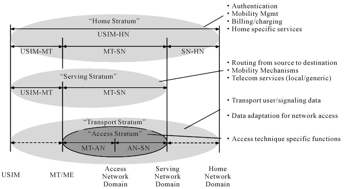
Figure 3. UMTS protocol stacks.
can be physically composed of zero, one or several physical interface(s), as e.g. The Iu, which is a reference point composed of the IuCS and the IuPS interfaces.
4. UMTS Feature Modeling
UMTS feature model will allow us to explore, identify, and define the key concepts of it so that these aspects can be described in Ontology [4].
Defining a feature model for the UMTS network provides means to explore, identify, and define the key architectural aspects of this cellular network so that it would make it more explicit, comprehensible, and comparable with other networks. These aspects can then be described more fully in Ontology. It is this Ontology that can be used to establish interoperability between cellular communication network systems.
Features are Organized in a hierarchical feature tree with classification (mandatory, optional, alternative, and/ or optional alternative features) [5].
• Mandatory. A mandatory child feature must be included in all the products in which its parent feature is included.
• Optional. An optional child feature can be optionally included in all products in which its parent feature appears.
• Alternative. A set of child features is defined as alternative, if only one of them can be selected when its parent feature is part of the product.
• Or-relation. A set of child features is said to have an or-relation with their parent when one or more of them can be included in the products in which its parent feature appears.
As shown in Figure 4, the feature model is defined around concepts. The objective is to model features of elements and structures of a domain, not just objects in that domain. The silhouette of the network architecture (figure) was inserted to point the relative size and composition of the entire feature tree. For more detail on the mechanism of how to construct a feature model, the reader may consult [4-6]. Figure 5 presents an excerpt of the UMTS feature model. It presents the UMTS functional architecture in a clear way via a hierarchic feature diagram.
5. Essential UMTS R 99 Network Characteristics
The selected essential UMTS network characteristics that will be accounted for in building interoperability Ontology for cellular network technologies are set forth in the following table.
6. UML as an Ontology Description Language
Drawing on the lesson learnt from the feature modeling, a method of integration of UML class diagrams will be presented [8-10], which supports interoperability. However, we should not forget that our focus is to tackle the interoperability issue between different network technologies. Modeling UMTS network classes using UML is one of the perquisite steps to achieve our objective.
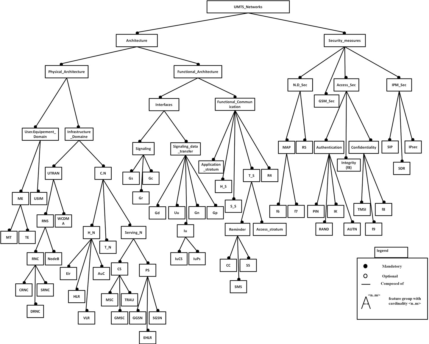
Figure 4. Feature model of UMTS network technology.
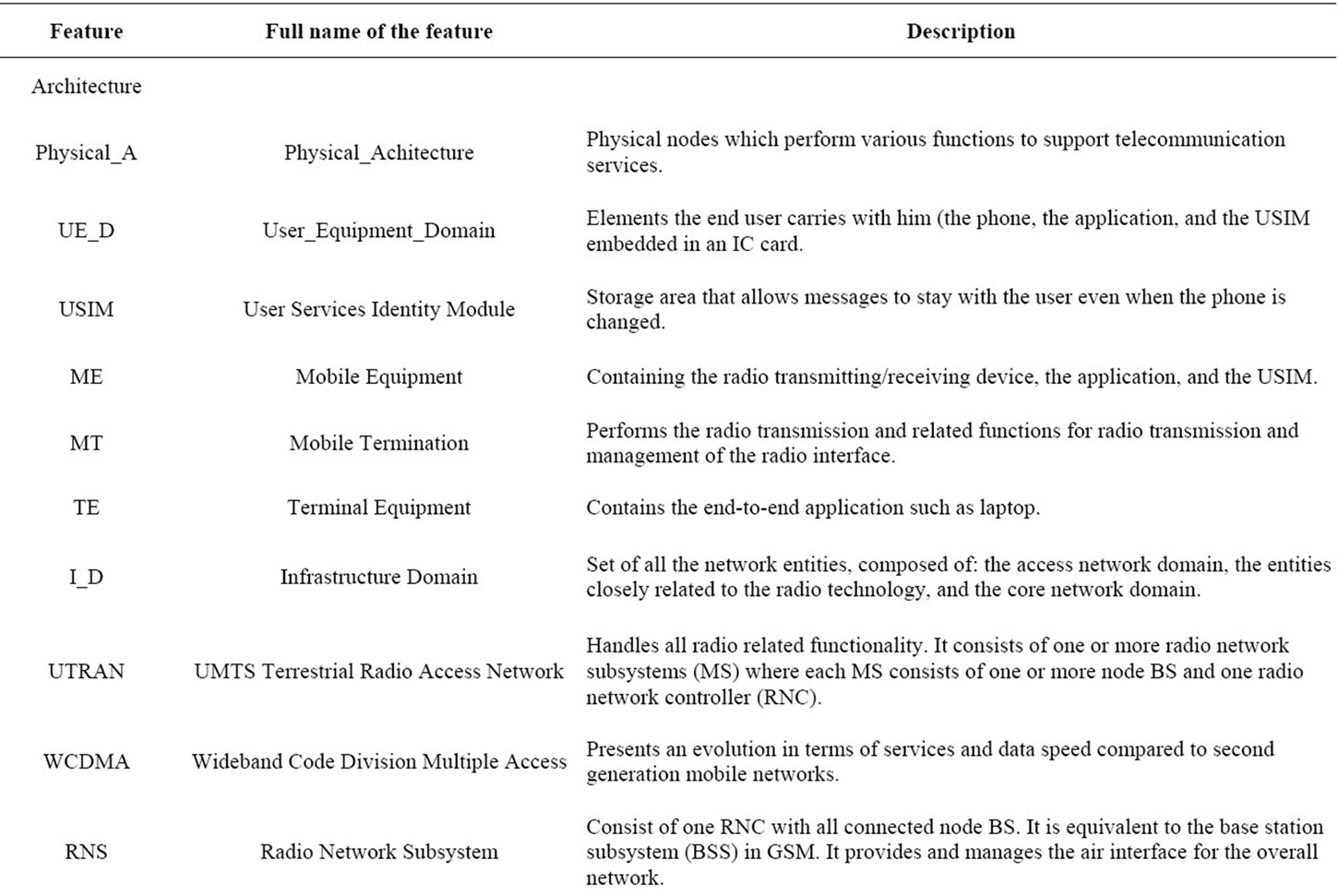

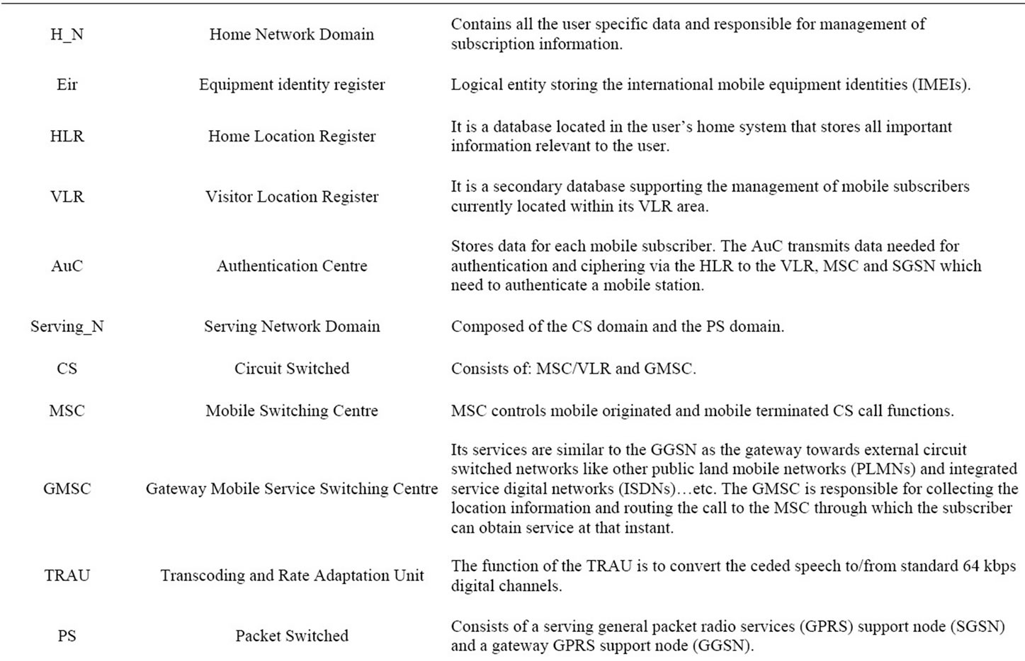
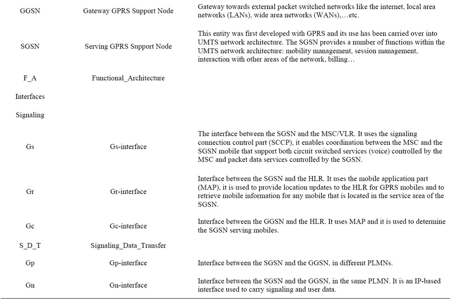
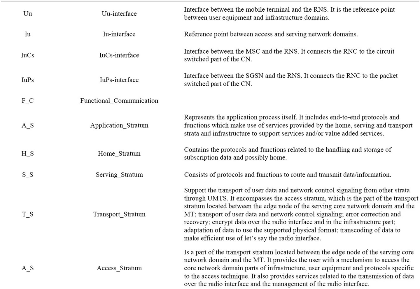
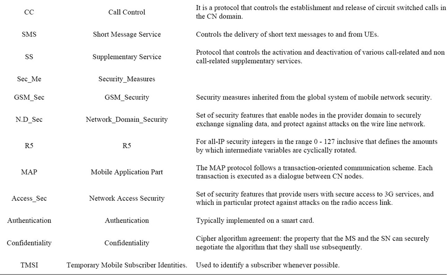
Table 1. UMTS R 99 network feature list.

Figure 5. Excerpt of the UMTS architecture feature model.
The next step is to integrate the hierarchical UML representations of three different networks into one global network highlighting the commonalities and the variabilities between the three network technologies.
The UML architecture has been designed to satisfy the following:
1) Modularity: networks construct into packages by providing strong cohesion and loose coupling [7].
2) Layering: support a package structure.
3) Partitioning: organize conceptual areas within the same layer.
4) Extensibility: can be extended in various ways.
5) Reuse: UML elements are based upon a flexible library that may be reused.
Class diagrams (Figure 6) Show the existing classes of real world system, and how they are associated with each other in a hierarchical manner. Figure 6 illustrates a Package (the only one grouping thing available for gathering structural and behavioral things) of a global UMTS class diagram. It is intended to show the relative size and composition of the entire Ontology; it will be further shown in smaller diagrams (such as in Figure 7 representing high level classes) easily readable and providing greater details.
As shown in Figure 7, each class is represented by a box with three parts: the first one at the top is for the name of the class, the second part is for the attributes of the class (specified by their name, type and visibility) and the third one is for the operations of the class (specified by name, argument list, return type and visibility).
For the purposes of annotating our Ontologies and to keep figures light and clear, we do list neither the attributes nor the operations.
Note that full diamond is the symbol of Composition

Figure 6. UML Description of UMTS network features.
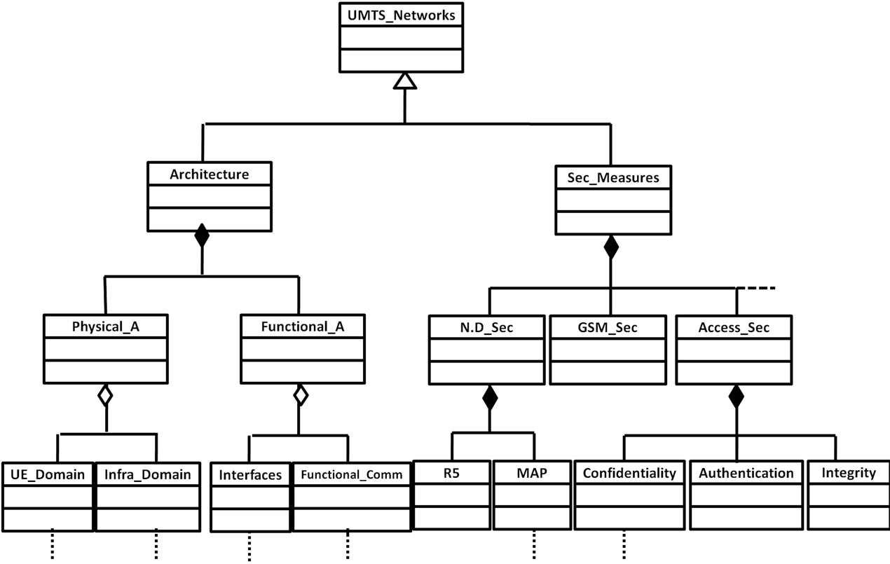
Figure 7. Excerpt from UMTS network class diagram.
(Strongly-owned), meanwhile the empty one represents an Aggregation (non-strongly owned).
7. Conclusion
The lack of interoperability between cellular access networks has long been a challenging burden, which telecommunication engineers and researchers are trying to overcome. A tentative approach to overcome this issue within heterogeneous networks begins by establishing a holistic understanding of cellular communication, and proposing an ontological framework that expresses the domain’s concepts, classes, and properties in a formal and unambiguous way. It begins by analyzing the structure of three different cellular technologies, and producing feature models. The UMTS cellular network feature tree is, in fact, not easily buildable, which will require from us to undertake seemingly heavy processes to identify existing features that may satisfy the representational needs.
REFERENCES
- N. Hasni and R. Bouallegue, “Roadmap for Establishing Interoperability of Heterogeneous Cellular Network Technologies -1-,” International Journal of Computer Science and Network Security, Vol. 12, No. 4, 2012, pp. 92-103.
- “Overview of 3GPP Release 99 Summary of all Release 99 Features” ETSI Mobile Competence Centre Version 05/03/04
- 3GPP spec. TR 21-905.
- K. Czarnecki and U. Eisenecker, “Generative Programming Methods, Tools, and Applications,” Addison-Wesley, Boston, 2000.
- L. Geyer, “Feature Modeling Using Design Spaces,” Proceedings of the 1st German Workshop on Product Line Software Engineering, Kaiserslautern, November 2000.
- N. Hasni, “Towards an interoperability Ontology for software development tools,” Master’s Thesis, Computer Science Department, Naval Postgraduate School, Monterey, 2003.
- “OMG Unified Modeling LanguageTM (OMG UML),” Superstructure Version 2.2, February 2009.
- P. Kogut, S. Cranefield, L. Hart, M. Dutra, K. Baclawski, M. Kokar and J. Smith, “UML for Ontology development,” Knowledge Engineering Review, Vol. 17, No. 1, 2002, pp. 61-64.
- S. Cranefield and M. Purvis, “UML as an Ontology Modelling Language,” Proceedings of the Workshop on Intelligent Information Integration, 16th International Joint Conference on Artificial Intelligence, Sweden, 1999, pp. 46-53.
- S. Cranefield, S. Haustein and M. Purvis, “UML-Based Ontology Modelling for Software Agents,” Proceedings of the Workshop on Ontologies in Agent Systems, 5th International Conference on Autonomous Agents, Montreal, 2001.