Paper Menu >>
Journal Menu >>
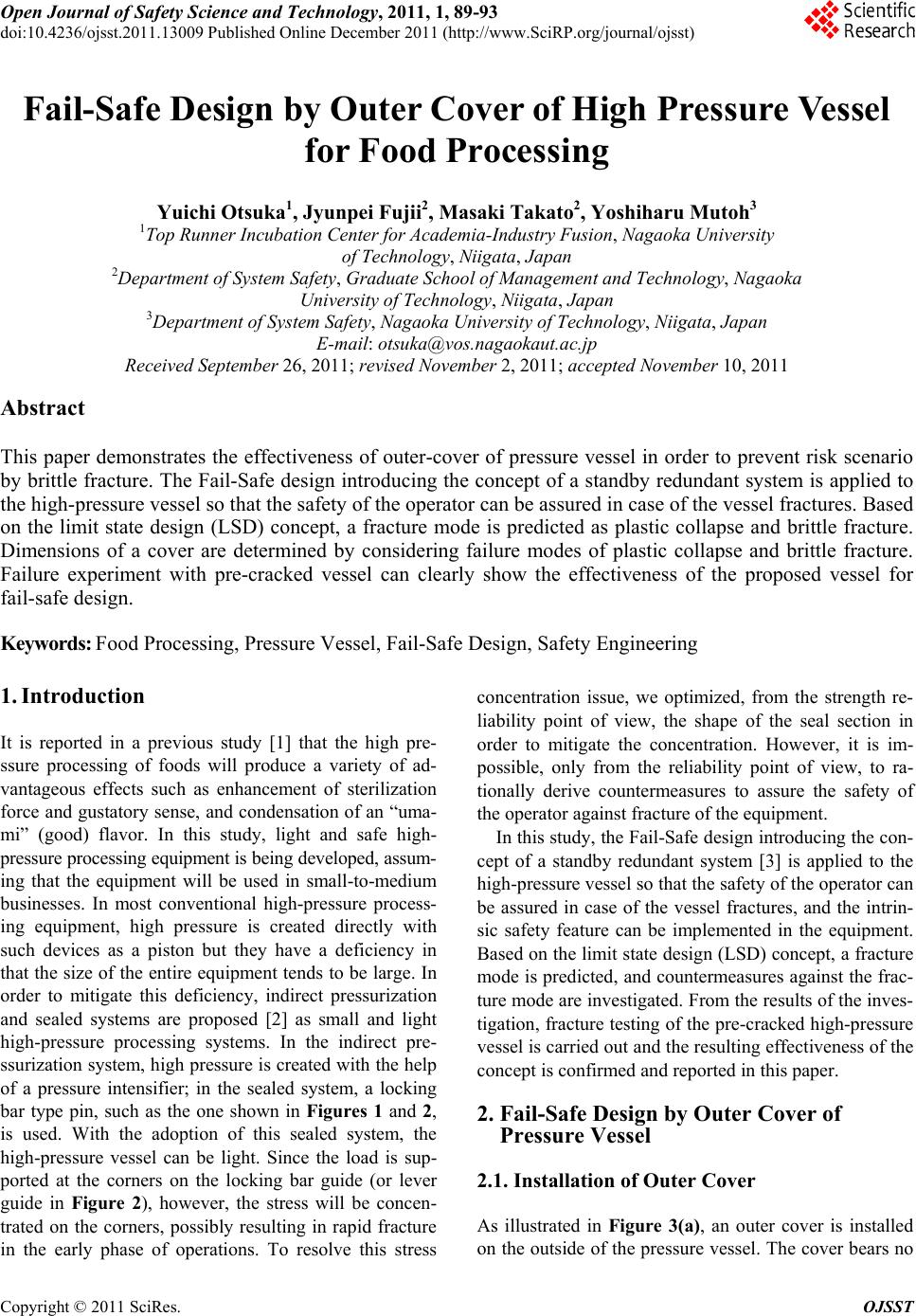 Open Journal of Safety Science and Technology, 2011, 1, 89 -93 doi:10.4236/ojsst.2011.13009 Published Online December 2011 (http://www.SciRP.org/journal/ojsst) Copyright © 2011 SciRes. OJSST Fail-Safe Desi gn b y O u te r Cover o f Hi g h Pressu re Vessel for Food Processing Yuichi Otsuka1, Jyunpei Fuj ii2, Masaki Takato2, Yoshiharu Mutoh3 1Top Runner Incubation Center for Academia-Industry Fusion, Nagaoka University of Technology, Niigata, Japan 2Department of System Safety, Graduate School of Management and Technology, Nagaoka University of Technology, Niigata, Japan 3Department of System Safety, Nagaoka University of Technology, Niigata, Japan E-mail: otsuka@vos.nagaokaut.ac.jp Received September 26, 2011; revised November 2, 2011; accepted November 10, 2011 Abstract This paper demonstrates the effectiveness of outer-cover of pressure vessel in order to prevent risk scenario by brittle fracture. The Fail-Safe design introducing the concept of a standby redundant system is applied to the high-pressure vessel so that the safety of the operator can be assured in case of the vessel fractures. Based on the limit state design (LSD) concept, a fracture mode is predicted as plastic collapse and brittle fracture. Dimensions of a cover are determined by considering failure modes of plastic collapse and brittle fracture. Failure experiment with pre-cracked vessel can clearly show the effectiveness of the proposed vessel for fail-safe design. Keywords: Food Processing, Pressure Vessel, Fail-Safe Design, Safety Engineering 1. Introduction It is reported in a previous study [1] that the high pre- ssure processing of foods will produce a variety of ad- vantageous effects such as enhancement of sterilization force and gustatory sense, and condensation of an “uma- mi” (good) flavor. In this study, light and safe high- pressure processing equipment is being developed, assum- ing that the equipment will be used in small-to-medium businesses. In most conventional high-pressure process- ing equipment, high pressure is created directly with such devices as a piston but they have a deficiency in that the size of the entire equipment tend s to be large. In order to mitigate this deficiency, indirect pressurization and sealed systems are proposed [2] as small and light high-pressure processing systems. In the indirect pre- ssurization system, high pressure is created with the help of a pressure intensifier; in the sealed system, a locking bar type pin, such as the one shown in Figures 1 and 2, is used. With the adoption of this sealed system, the high-pressure vessel can be light. Since the load is sup- ported at the corners on the locking bar guide (or lever guide in Figure 2), however, the stress will be concen- trated on the corners, possibly resulting in rapid fracture in the early phase of operations. To resolve this stress concentration issue, we optimized, from the strength re- liability point of view, the shape of the seal section in order to mitigate the concentration. However, it is im- possible, only from the reliability point of view, to ra- tionally derive countermeasures to assure the safety of the operator against fracture of the equipment. In this study, the Fail-Safe design introducing the con- cept of a standby redundant system [3] is applied to the high-pressure vessel so that th e safety of the op erator can be assured in case of the vessel fractures, and the intrin- sic safety feature can be implemented in the equipment. Based on the limit state design (LSD) concept, a fracture mode is predicted, and countermeasures against the frac- ture mode are investigated. From the results of th e inves- tigation, fracture testing of the pre-cracked high-pressure vessel is carried out and the resulting effectiveness of the concept is confirmed and reported in this paper. 2. Fail-Safe Design by Outer Cover of Pressure Vessel 2.1. Installation of Outer Cover As illustrated in Figure 3(a), an outer cover is installed on the outside of the pressure vessel. The cover bears no 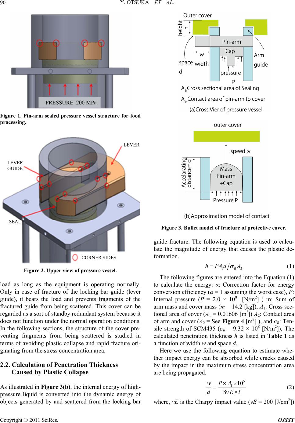 Y. OTSUKA ET AL. 90 Figure 1. Pin-arm sealed pressure vessel structure for food processing. Figure 2. Upper view of pressure vessel. load as long as the equipment is operating normally. Only in case of fracture of the locking bar guide (lever guide), it bears the load and prevents fragments of the fractured guide from being scattered. This cover can be regarded as a sort of standby redundant system because it does not function under the normal operation condition s. In the following sections, the structure of the cover pre- venting fragments from being scattered is studied in terms of avoiding plastic collapse and rapid fracture ori- ginating from the stress concentration area. 2.2. Calculation of Penetration Thickness Caused by Plastic Collapse As illustrated in Figure 3(b), the internal energy of high- pressure liquid is converted into the dynamic energy of objects generated by and scattered from the locking bar Figure 3. Bullet model of fracture of protective cover. guide fracture. The following equation is used to calcu- late the magnitude of energy that causes the plastic de- formation. 1B hPAd A 2 (1) The following figures are entered into the Equ ation (1) to calculate the energy: α: Correction factor for energy conversion efficiency (α = 1 assuming the worst case), P: Internal pressure (P = 2.0 × 10⁸ [N/m2] ) m: Sum of arm mass and cover mass (m = 14.2 [kg]), A1: Cross sec- tional area of cover (A1 = 0.01606 [m2]) A2: Contact area of arm and cover (A2 = See Figure 4 [m2] ), and σB: Ten- sile strength of SCM435 (σB = 9.32 × 10⁸ [N/m2]). The calculated penetration thickness h is listed in Table 1 as a function of width w and space d. Here we use the following equation to estimate whe- ther impact energy can be absorbed while cracks caused by the impact in the maximum stress concentration area are being propagated. 5 110 8 PA w dEl (2) where, νE is the Charpy impact value (νE = 200 [J /cm2]) Copyright © 2011 SciRes. OJSST 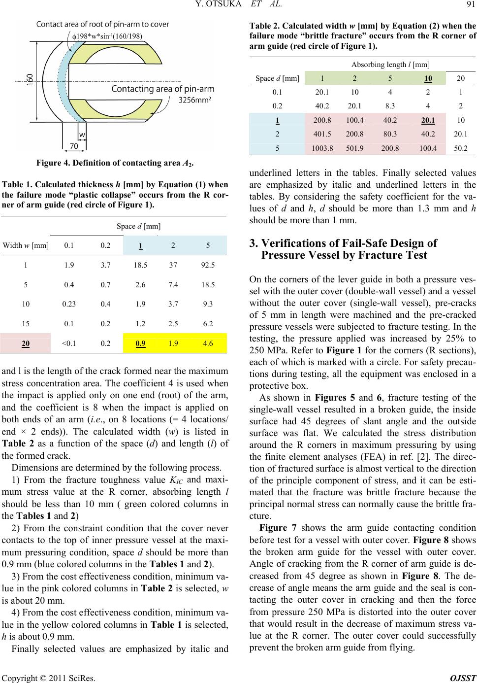 Y. OTSUKA ET AL.91 Figure 4. Definition of contacting area A2. Table 1. Calculated thickness h [mm] by Equation (1) when the failure mode “plastic collapse” occurs from the R cor- ner of arm guide (red circle of Figure 1). Space d [mm] Width w [mm] 0.1 0.2 1 2 5 1 1.9 3.7 18.5 37 92.5 5 0.4 0.7 2.6 7.4 18.5 10 0.23 0.4 1.9 3.7 9.3 15 0.1 0.2 1.2 2.5 6.2 20 <0.1 0.2 0.9 1.9 4.6 and l is the length of the crack formed near the maximum stress concentration area. The coefficient 4 is used when the impact is applied only on one end (root) of the arm, and the coefficient is 8 when the impact is applied on both ends of an arm (i.e., on 8 locations (= 4 locations/ end × 2 ends)). The calculated width (w) is listed in Table 2 as a function of the space (d) and length (l) of the formed crack. Dimensions are determined by the following pro cess. 1) From the fracture toughness value KIC and maxi- mum stress value at the R corner, absorbing length l should be less than 10 mm ( green colored columns in the Tables 1 and 2) 2) From the constraint condition that the cover never contacts to the top of inner pressure vessel at the maxi- mum pressuring condition, space d should be more than 0.9 mm (blue colored columns in the Tables 1 and 2). 3) From the cost effectiveness condition, minimum va- lue in the pink colored columns in Ta ble 2 is selected, w is about 20 mm. 4) From the cost effectiveness condition, minimum va- lue in the yellow colored co lumns in Table 1 is selected, h is about 0.9 mm. Finally selected values are emphasized by italic and Table 2. Calculated width w [mm] by Equation (2) when the failure mode “brittle fracture” occurs from the R corner of arm guide (red circle of Figure 1). Absorbing length l [mm] Space d [mm] 1 2 5 10 20 0.1 20.1 10 4 2 1 0.2 40.2 20.1 8.3 4 2 1 200.8 100.4 40.2 20.1 10 2 401.5 200.8 80.3 40.2 20.1 5 1003.8501.9 200.8 100.4 50.2 underlined letters in the tables. Finally selected values are emphasized by italic and underlined letters in the tables. By considering the safety coefficient for the va- lues of d and h, d should be more than 1.3 mm and h should be more than 1 mm. 3. Verifications of Fail-Safe Design of Pressure Vessel by Fracture Test On the corners of the lever guide in both a pressure ves- sel with the outer cover (double-wall vessel) and a vessel without the outer cover (single-wall vessel), pre-cracks of 5 mm in length were machined and the pre-cracked pressure vessels were subjected to fracture testing. In the testing, the pressure applied was increased by 25% to 250 MPa. Refer to Figure 1 for the corners (R sections), each of which is marked with a circle. For safety precau- tions during testing, all the equipment was enclosed in a protective box. As shown in Figures 5 and 6, fracture testing of the single-wall vessel resulted in a broken guide, the inside surface had 45 degrees of slant angle and the outside surface was flat. We calculated the stress distribution around the R corners in maximum pressuring by using the finite element analyses (FEA) in ref. [2]. The direc- tion of fractured surface is almost vertical to the direction of the principle component of stress, and it can be esti- mated that the fracture was brittle fracture because the principal normal stress can normally cause the brittle fra- cture. Figure 7 shows the arm guide contacting condition before test for a v essel with outer cover. Figure 8 show s the broken arm guide for the vessel with outer cover. Angle of cracking from the R corner of arm guide is de- creased from 45 degree as shown in Figure 8. The de- crease of angle means the arm guide and the seal is con- tacting the outer cover in cracking and then the force from pressure 250 MPa is distorted into the outer cover that would result in the decrease of maximum stress va- lue at the R corner. The outer cover could successfully prevent the broken arm guide from flying. Copyright © 2011 SciRes. OJSST 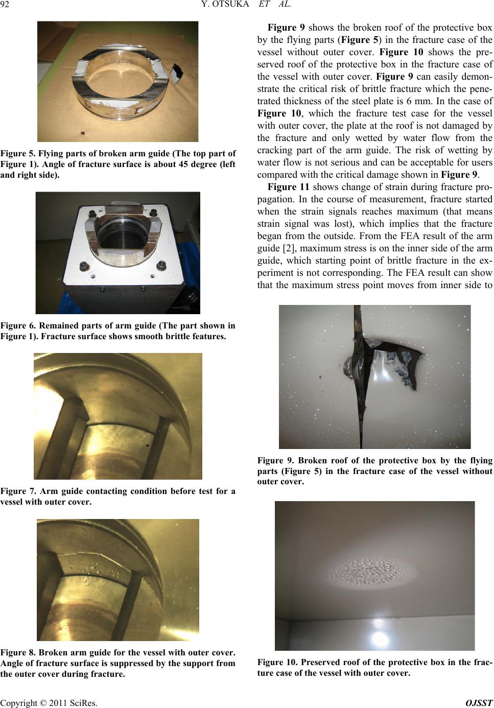 Y. OTSUKA ET AL. 92 Figure 5. Flying parts of broken arm guide (The top part of Figure 1). Angle of fracture surface is about 45 degree (left and right side). Figure 6. Remained parts of arm guide (The part shown in Figure 1). Fracture surface shows smooth brittle features. Figure 7. Arm guide contacting condition before test for a vessel with outer cover. Figure 8. Broken arm guide for the vessel with outer cover. Angle of fracture surface is suppressed by the support from the outer cover during fracture. Figure 9 shows the broken roof of the protective box by the flying parts (Figure 5) in the fracture case of the vessel without outer cover. Figure 10 shows the pre- served roof of the protective box in the fracture case of the vessel with outer cover. Figure 9 can easily demon- strate the critical risk of brittle fracture which the pene- trated thickness of the steel plate is 6 mm. In the case of Figure 10, which the fracture test case for the vessel with outer cover, the plate at the roof is not damaged by the fracture and only wetted by water flow from the cracking part of the arm guide. The risk of wetting by water flow is not serious and can be acceptable for users compared with the critical damage shown in Figure 9. Figure 11 shows change of strain during fracture pro- pagation. In the course of measurement, fracture started when the strain signals reaches maximum (that means strain signal was lost), which implies that the fracture began from the outside. From the FEA result of the arm guide [2], maximum stress is on the inner side of the arm guide, which starting point of brittle fracture in the ex- periment is not corresponding. The FEA result can show that the maximum stress point moves from inner side to Figure 9. Broken roof of the protective box by the flying parts (Figure 5) in the fracture case of the vessel without outer cover. Figure 10. Preserved roof of the protective box in the frac- ture case of the vessel with outer cover. Copyright © 2011 SciRes. OJSST  Y. OTSUKA ET AL. Copyright © 2011 SciRes. OJSST 93 Figure 11. Change of strain during fracture propagation. outer side when the sliding of the arm or cleara nce of th e arm is considered. This analysis indicates the necessity of improvement of contacting conditions between arm and arm guide. 4. Conclusions A double-wall high-pressure vessel in which the concept of the standby redundant system is introduced was pro- posed. The dimensions of the outer cover were decided by calculations that take the fracture mode into account, and fracture testing verifies the effectiveness of the outer cover. This research was financially supported by JST project “Development of Technology for Promoting Food Quality”. 5. References [1] Development of basic technologies available to Enhanc- ing Value-Added to Food. http://www.nico.or.jp/ create/gaiyou/index.html [2] H. B. Haron, Y. Mutoh, Y. Otsuka and Y. Miyashita, “Selection of Stress Relief Grooves On Pressure Vessels for Food Processing,” Proceedings of JSME Hokuriku Sinetsu Branch 48th General Conference and Lecture Meeting CD-ROM (No. 616), Ueda, 8 March 2011. [3] M. G. Stewart and R. E. Melchers, “Probabilistic Risk Assessment of Engineering Systems,” Morikita Publish- ing Inc., Tokyo, 2003. |