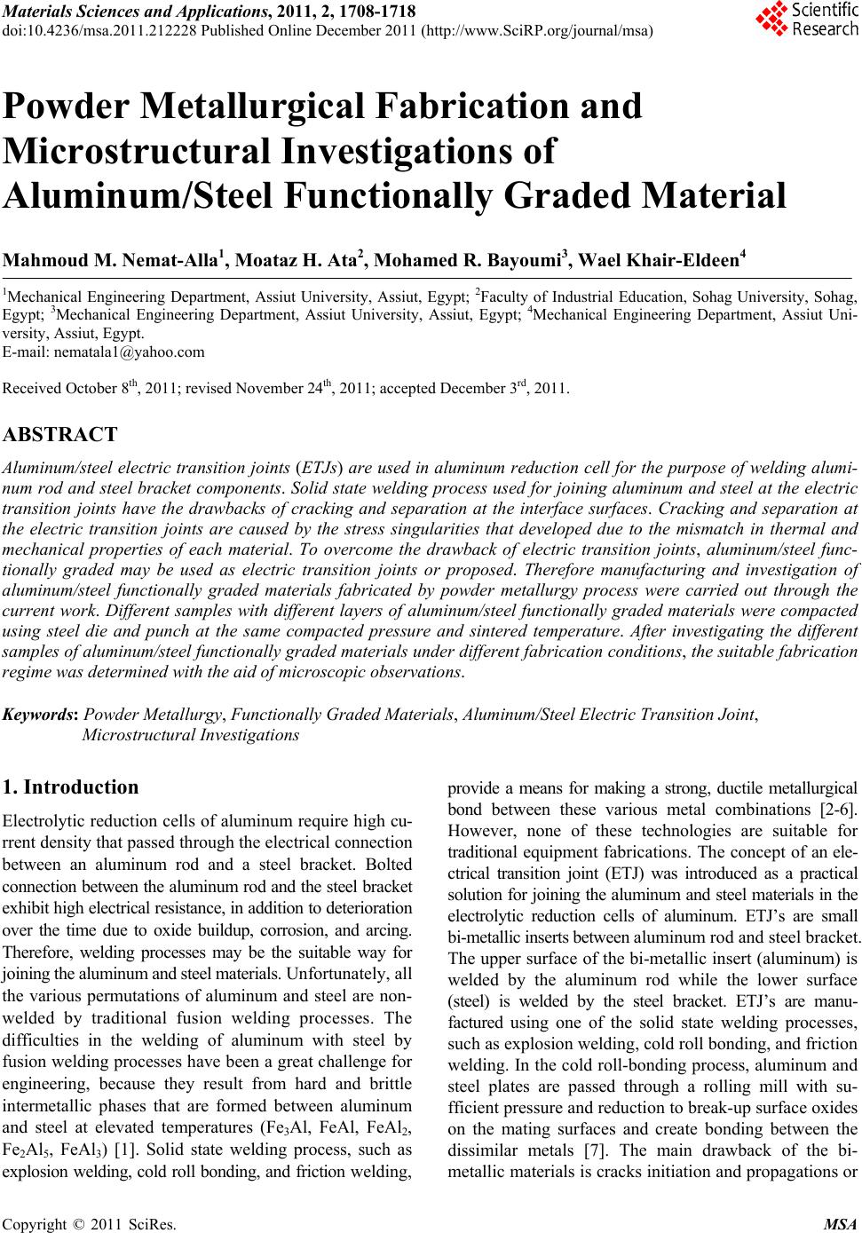
 Materials Sciences and Applicatio ns, 2011, 2, 1708-1718 doi:10.4236/msa.2011.212228 Published Online December 2011 (http://www.SciRP.org/journal/msa) Copyright © 2011 SciRes. MSA Powder Metallurgical Fabrication and Microstructural Investigations of Aluminum/Steel Functionally Graded Material Mahmoud M. Nemat-Alla1, Moataz H. Ata2, Mohamed R. Bayoumi3, Wael Khair-Eldeen4 1Mechanical Engineering Department, Assiut University, Assiut, Egypt; 2Faculty of Industrial Education, Sohag University, Sohag, Egypt; 3Mechanical Engineering Department, Assiut University, Assiut, Egypt; 4Mechanical Engineering Department, Assiut Uni- versity, Assiut, Egypt. E-mail: nematala1@yahoo.com Received October 8th, 2011; revised November 24th, 2011; accepted December 3rd, 2011. ABSTRACT Aluminum/steel electric transition jo ints (ETJs) are used in aluminum reduction cell for the purpose of welding alumi- num rod and steel bracket components. Solid state welding process used for joining aluminum and steel at the electric transition joints have the drawbacks of cracking and separation at the interface surfaces. Cracking and separation at the electric transition joints are caused by the stress singularities that developed due to the mismatch in thermal and mechanical properties of each material. To overcome the drawback of electric transition joints, aluminum/steel func- tionally graded may be used as electric transition joints or proposed. Therefore manufacturing and investigation of aluminum/steel functionally graded materials fabricated by powder metallurgy process were carried out through the current work. Different samples with different layers of aluminum/steel functionally graded materials were compacted using steel die and punch at the same compacted pressure and sintered temperature. After investigating the different samples of aluminu m/steel functio nally grad ed materials u nder differen t fabrication condition s, the suitable fabrica tion regime was determined with the aid of microscopic observations. Keywords: Powder Metallurgy, Functionally Graded Materials, Aluminum/Steel Electric Transition Joint, Microstructural Investigations 1. Introduction Electrolytic reduction cells of aluminum requ ire high cu- rrent density that passed through the electrical connection between an aluminum rod and a steel bracket. Bolted connection between the aluminum rod and the steel bracket exhibit high electrical resistance, in addition to deterioration over the time due to oxide buildup, corrosion, and arcing. Therefore, welding processes may be the suitable way for joining the aluminum and steel m aterials. Unfortunately, all the various permutations of aluminum and steel are non- welded by traditional fusion welding processes. The difficulties in the welding of aluminum with steel by fusion welding processes have been a great challenge for engineering, because they result from hard and brittle intermetallic phases that are formed between aluminum and steel at elevated temperatures (Fe3Al, FeAl, FeAl2, Fe2Al5, FeAl3) [1]. Solid state welding process, such as explosion welding, cold roll bonding, and friction w eld in g, provide a means for making a strong, ductile metallurgical bond between these various metal combinations [2-6]. However, none of these technologies are suitable for traditional equipment fabrications. The concept of an ele- ctrical transition joint (ETJ) was introduced as a practical solut ion for joining th e aluminum and steel materia ls in the electrolytic reduction cells of aluminum. ETJ’s are small bi-metallic inserts between alum inum rod and st ee l br ac ket . The upper surface of the bi-metallic insert (aluminum) is welded by the aluminum rod while the lower surface (steel) is welded by the steel bracket. ETJ’s are manu- factured using one of the solid state welding processes, such as explosion welding , cold ro ll bond ing, and friction welding. In the cold roll-bonding process, alu minum and steel plates are passed through a rolling mill with su- fficient pressure and reduction to break-up surface oxides on the mating surfaces and create bonding between the dissimilar metals [7]. The main drawback of the bi- metallic materials is cracks initiation and propagations or 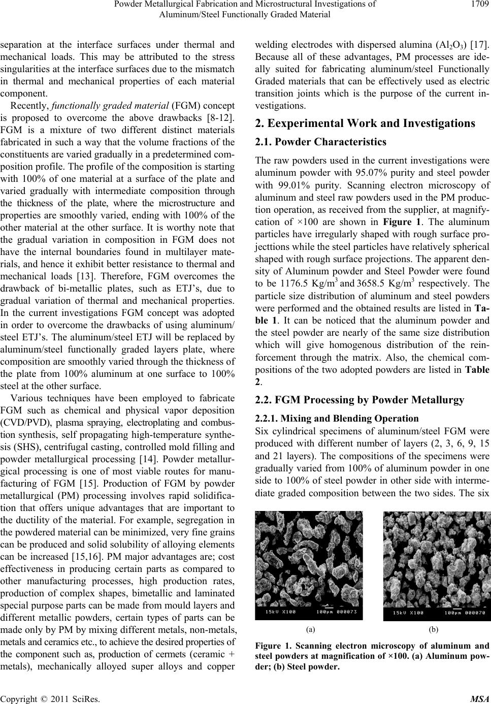 Powder Metallurgical Fabrication and Microstructural Investigations of 1709 Aluminum/Steel Functionally Graded Material separation at the interface surfaces under thermal and mechanical loads. This may be attributed to the stress singularities at the interface surfaces due to the mismatch in thermal and mechanical properties of each material component. Recently, functionally graded material (FGM) concept is proposed to overcome the above drawbacks [8-12]. FGM is a mixture of two different distinct materials fabricated in such a way that the volume fractions of the constituents are varied gradually in a pr edetermined com- position prof ile. The profile of the co mposition is starting with 100% of one material at a surface of the plate and varied gradually with intermediate composition through the thickness of the plate, where the microstructure and properties are smoothly varied, ending with 100% of the other material at the other surface. It is worthy note that the gradual variation in composition in FGM does not have the internal boundaries found in multilayer mate- rials, and hence it exhibit better resistance to thermal and mechanical loads [13]. Therefore, FGM overcomes the drawback of bi-metallic plates, such as ETJ’s, due to gradual variation of thermal and mechanical properties. In the current investigations FGM concept was adopted in order to overcome the drawbacks of using aluminum/ steel ETJ’s. The aluminum/steel ETJ will be replaced by aluminum/steel functionally graded layers plate, where composition are smoothly varied through the th ickness of the plate from 100% aluminum at one surface to 100% steel at the other surface. Various techniques have been employed to fabricate FGM such as chemical and physical vapor deposition (CVD/PVD), plasma spraying, electroplating and combus- tion synthesis, self propagating high-temperature synthe- sis (SHS), centrifugal casting, controlled mold fillin g and powder metallurgical processing [14]. Powder metallur- gical processing is one of most viable routes for manu- facturing of FGM [15]. Production of FGM by powder metallurgical (PM) processing involves rapid solidifica- tion that offers unique advantages that are important to the ductility of the material. For example, segregation in the powdered material can be minimized, very fine grains can be produced and solid solu bility of allo ying elements can be increased [15,16]. PM major advantages are; cost effectiveness in producing certain parts as compared to other manufacturing processes, high production rates, production of complex shapes, bimetallic and laminated special purpose parts can be made from mould layers and different metallic powders, certain types of parts can be made only by PM by mixing different metals, non-metals, metals and ceramics etc., to achieve the desired properties of the component such as, production of cermets (ceramic + metals), mechanically alloyed super alloys and copper welding electrodes with dispersed alumina (Al2O3) [17]. Because all of these advantages, PM processes are ide- ally suited for fabricating aluminum/steel Functionally Graded materials that can be effectively used as electric transition joints which is the purpose of the current in- vestigations. 2. Eexperimental Work and Investigations 2.1. Powder Characteristics The raw powders used in the current investigations were aluminum powder with 95.07% purity and steel powder with 99.01% purity. Scanning electron microscopy of aluminum and steel raw powders used in the PM produc- tion operation, as received from the supplier, at magnify- cation of ×100 are shown in Figure 1. The aluminum particles have irregularly sh aped with rough surface pro- jecttions while the steel particles have relatively sph e rical shaped with rough surface projections. The apparent den- sity of Aluminum powder and Steel Powder were found to be 1176.5 Kg/m3 and 3658.5 Kg/m3 respectively. The particle size distribution of aluminum and steel powders were performed and the obtained results are listed in Ta- ble 1. It can be noticed that the aluminum powder and the steel powder are nearly of the same size distribution which will give homogenous distribution of the rein- forcement through the matrix. Also, the chemical com- positions of the two adopted powders are listed in Table 2. 2.2. FGM Processing by Powder Metallurgy 2.2.1. Mixing and Blending O pe ration Six cylindrical specimens of aluminum/steel FGM were produced with different number of layers (2, 3, 6, 9, 15 and 21 layers). The compositions of the specimens were gradually varied from 100% of aluminum powder in one side to 100% of steel powder in other side with interme- diate graded composition between the two sides. The six (a) (b) Figure 1. Scanning electron microscopy of aluminum and steel powders at magnification of ×100. (a) Aluminum pow- der; (b) Steel powder. Copyright © 2011 SciRes. MSA 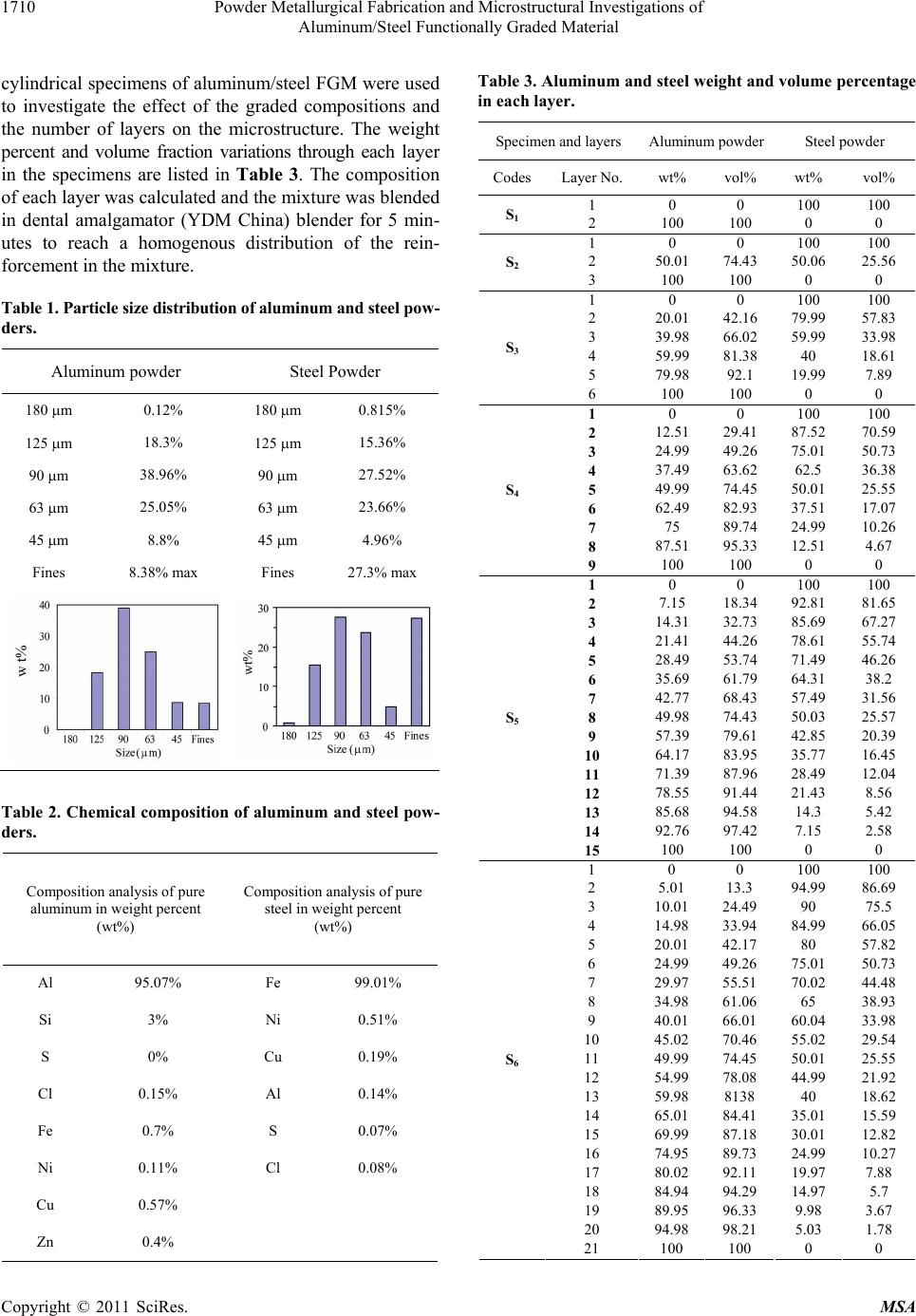 Powder Metallurgical Fabrication and Microstructural Investigations of 1710 Aluminum/Steel Functionally Graded Material cylindrical specimens of aluminum/steel FGM were used to investigate the effect of the graded compositions and the number of layers on the microstructure. The weight percent and volume fraction variations through each layer in the specimens are listed in Table 3. The composition of each layer was calculated and the mixture was blended in dental amalgamator (YDM China) blender for 5 min- utes to reach a homogenous distribution of the rein- forcement in the mixture. Table 1. Particle size distribution of aluminum and steel pow- ders. Aluminum powder Steel Powder 180 m 0.12% 180 m 0.815% 125 m 18.3% 125 m 15.36% 90 m 38.96% 90 m 27.52% 63 m 25.05% 63 m 23.66% 45 m 8.8% 45 m 4.96% Fines 8.38% max Fines 27.3% max Table 2. Chemical composition of aluminum and steel pow- ders. Composition analysis of pure aluminum in weight percent (wt%) Composition analysis of pure steel in weight percent (wt%) Al 95.07% Fe 99.01% Si 3% Ni 0.51% S 0% Cu 0.19% Cl 0.15% Al 0.14% Fe 0.7% S 0.07% Ni 0.11% Cl 0.08% Cu 0.57% Zn 0.4% Table 3. Aluminum and steel w eight and volume per centage in each layer. Specimen and layers Aluminum powder Steel powder CodesLayer No. wt% vol% wt% vol% 1 0 0 100 100 S1 2 100 100 0 0 1 0 0 100 100 2 50.01 74.43 50.06 25.56 S2 3 100 100 0 0 1 0 0 100 100 2 20.01 42.16 79.99 57.83 3 39.98 66.02 59.99 33.98 4 59.99 81.38 40 18.61 5 79.98 92.1 19.99 7.89 S3 6 100 100 0 0 1 0 0 100 100 2 12.51 29.41 87.52 70.59 3 24.99 49.26 75.01 50.73 4 37.49 63.62 62.5 36.38 5 49.99 74.45 50.01 25.55 6 62.49 82.93 37.51 17.07 7 75 89.74 24.99 10.26 8 87.51 95.33 12.51 4.67 S4 9 100 100 0 0 1 0 0 100 100 2 7.15 18.34 92.81 81.65 3 14.31 32.73 85.69 67.27 4 21.41 44.26 78.61 55.74 5 28.49 53.74 71.49 46.26 6 35.69 61.79 64.31 38.2 7 42.77 68.43 57.49 31.56 8 49.98 74.43 50.03 25.57 9 57.39 79.61 42.85 20.39 10 64.17 83.95 35.77 16.45 11 71.39 87.96 28.49 12.04 12 78.55 91.44 21.43 8.56 13 85.68 94.58 14.3 5.42 14 92.76 97.42 7.15 2.58 S5 15 100 100 0 0 1 0 0 100 100 2 5.01 13.3 94.99 86.69 3 10.01 24.49 90 75.5 4 14.98 33.94 84.99 66.05 5 20.01 42.17 80 57.82 6 24.99 49.26 75.01 50.73 7 29.97 55.51 70.02 44.48 8 34.98 61.06 65 38.93 9 40.01 66.01 60.04 33.98 10 45.02 70.46 55.02 29.54 11 49.99 74.45 50.01 25.55 12 54.99 78.08 44.99 21.92 13 59.98 8138 40 18.62 14 65.01 84.41 35.01 15.59 15 69.99 87.18 30.01 12.82 16 74.95 89.73 24.99 10.27 17 80.02 92.11 19.97 7.88 18 84.94 94.29 14.97 5.7 19 89.95 96.33 9.98 3.67 20 94.98 98.21 5.03 1.78 S6 21 100 100 0 0 Copyright © 2011 SciRes. MSA  Powder Metallurgical Fabrication and Microstructural Investigations of 1711 Aluminum/Steel Functionally Graded Material 2.2.2. C ompaction The die, upper and lower punches were lubricated using Zinc stearate fine powder, to prevent adhesion of powder with die surface and decrease the coefficient of friction between die bore surface and powder, then the lower punch was assembled with the die cavity. Two different techniques of powder compaction were used in the current study. First one is, after mixing and blending process for the composition of each layer it was pre-compacted un- der low pressure before stacking the next layer. After that all layers compacted at 990.694 MPa ( correspond to ma- chine load of 35 ton) at a press of 500 ton capacity pro- duced by (werkstoffprufmaschinen WPM Germany). Three layers (S2) and 6-layers (S3) specimens were fab- ricated using this technique. After compaction it was found that separation occurred between the green speci- men layers, this may be attributed to the separating sur- face formed through the layer interface as shown in Fig- ures 2(a) and (b). To avoid separating surface occurred when using the first technique, the mixed powders were sequentially stacked in the die, layer by layer, with a stepwise compositional distributions. Also, the specimen was compacted at 990.7 MPa w ithout pre-compaction pres- sure. This was the second technique. The compositional of the specimen changes from 100% steel to 100% alu- minum through the different layers. Using the second technique it was found that no separation occurred be- tween layers in green specimens. Also, it seems that good mechanical interlock between the different layers of the specimen is achiev ed. New six specimens (S1, S2, S3, S4, S5 and S6) were compacted successfully using the second technique. 2.2.3. Sintering Process Green compact specimen cannot be used because it has many drawbacks. In order to overcome such drawbacks sintering process is needed. The sintering temperature for powder varies in the range from 0.7 to 0.9 of the melting point. Due to variation of the melting temperature of the basic components of the specimen, aluminum and steel, two sets of sintering temperature were adopted, 800˚C and 600˚C. The adopted sets of sintering temperature were above and below the melting point of aluminum. Usually, sintering time depends upon the specimen di- mensions and type of the metal. However for Alnico magnets, it is 2 h. [18]. After sintering process it was found that failure occurred in specimens that sintered at 800˚C. This failure can be attributed to a new compound that has formed between aluminum and steel at elevated temperature. Therefore, the sintering temperature should be less than the melting point of both powders consti- tutes. All six specimens with different number of layers and compositions, as listed in Tab le 3, that sintered at 600˚C for 2 h will be adopted through the current investigations . Finally, the fabrication scheme, of aluminum/steel func- tionally graded materials, that used in the current invest- tigations can be schematically summarized as shown in Figure 3. 3. Results and Discussion Six cylindrical aluminum/steel FGM specimens were fa- bricated with 21 mm diameter and 28 mm approximately height. Specimens for microstructural inspection were sliced with a diamond saw perpendicular to layer surface, and their surfaces were ground, polished carefully and ex- amined using standard metallographic techniques. Macro- and Microstructural features were characterized by opti- cal microscopy (OM) and scanning electron microscopy (SEM) with (EDS) analysis using (JEDL-JSM 5400 LV) microscope. (a) (b) Figure 2. Compacted specimens with separating surfaces. Figure 3. Flow chart of PM fabrication of functionally gra- ded material . Copyright © 2011 SciRes. MSA 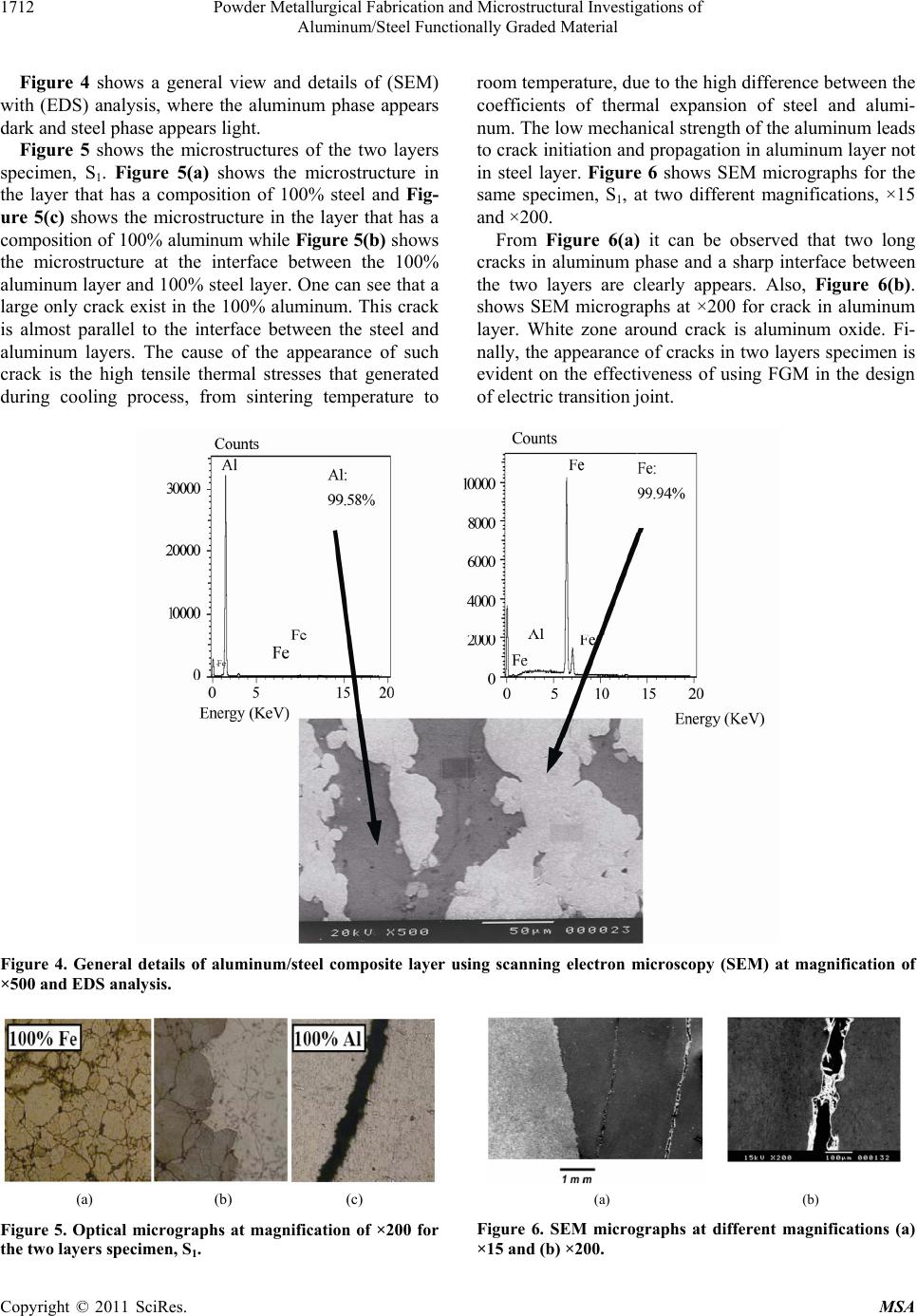 Powder Metallurgical Fabrication and Microstructural Investigations of Aluminum/Steel Functionally Graded Material Copyright © 2011 SciRes. MSA 1712 Figure 4 shows a general view and details of (SEM) with (EDS) analysis, where the aluminum phase appears dark and steel phase appears light. Figure 5 shows the microstructures of the two layers specimen, S1. Figure 5(a) shows the microstructure in the layer that has a composition of 100% steel and Fig- ure 5(c) shows the microstructure in the layer that has a composition of 100% aluminum while Figure 5(b) shows the microstructure at the interface between the 100% aluminum layer and 100% steel layer. One can see that a large only crack exist in the 10 0% aluminum. This crack is almost parallel to the interface between the steel and aluminum layers. The cause of the appearance of such crack is the high tensile thermal stresses that generated during cooling process, from sintering temperature to room temperature, due to the high difference between the coefficients of thermal expansion of steel and alumi- num. The low mechanical strength of the aluminum leads to crack initiatio n and propagation in aluminum layer not in steel layer. Figure 6 shows SEM micrographs for the same specimen, S1, at two different magnifications, ×15 and ×200. From Figure 6(a) it can be observed that two long cracks in aluminum phase and a sharp interface between the two layers are clearly appears. Also, Figure 6(b). shows SEM micrographs at ×200 for crack in aluminum layer. White zone around crack is aluminum oxide. Fi- nally, the appearance of cracks in two layers specimen is evident on the effectiveness of using FGM in the design of electric transition joint. Figure 4. General details of aluminum/steel composite layer using scanning electron microscopy (SEM) at magnification of ×500 and EDS analysis. (a) (b) (c) (a) (b) Figure 6. SEM micrographs at different magnifications (a) ×15 and (b) ×200. Figure 5. Optical micrographs at magnification of ×200 for the two layers specimen, S1. 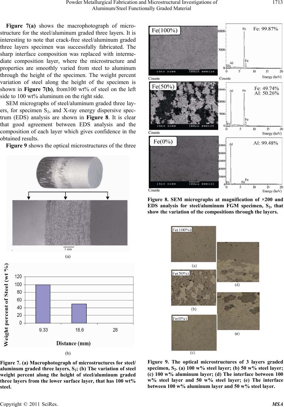 Powder Metallurgical Fabrication and Microstructural Investigations of 1713 Aluminum/Steel Functionally Graded Material Figure 7(a) shows the macrophotograph of micro- structure for the steel/aluminum graded three layers. It is interesting to note that crack-free steel/aluminum graded three layers specimen was successfully fabricated. The sharp interface composition was replaced with interme- diate composition layer, where the microstructure and properties are smoothly varied from steel to aluminum through the height of the specimen. The weight percent variation of steel along the height of the specimen is shown in Figure 7(b), from100 wt% of steel on the left side to 100 wt% aluminum on the right side. SEM micrographs of steel/aluminum graded three lay- ers, for specimen S2, and X-ray energy dispersive spec- trum (EDS) analysis are shown in Figure 8. It is clear that good agreement between EDS analysis and the composition of each layer which gives confidence in the obtained re sults. Figure 9 shows the optical microstructures of the three (a) (b) Figure 7. (a) Macrophotograph of microstructures for steel/ aluminum graded three layers, S2; (b) The variation of steel weight percent along the height of steel/aluminum graded three layers from the lower surface layer, that has 100 wt% steel. Figure 8. SEM micrographs at magnification of ×200 and EDS analysis for steel/aluminum FGM specimen, S2, that show the variation of the compositions through the layers. Figure 9. The optical microstructures of 3 layers graded specimen, S2. (a) 100 w% steel layer; (b) 50 w% steel layer; (c) 100 w% aluminum layer; (d) The interface between 100 w% steel layer and 50 w% steel layer; (e) The interface between 100 w% aluminum layer and 50 w% steel layer. Copyright © 2011 SciRes. MSA 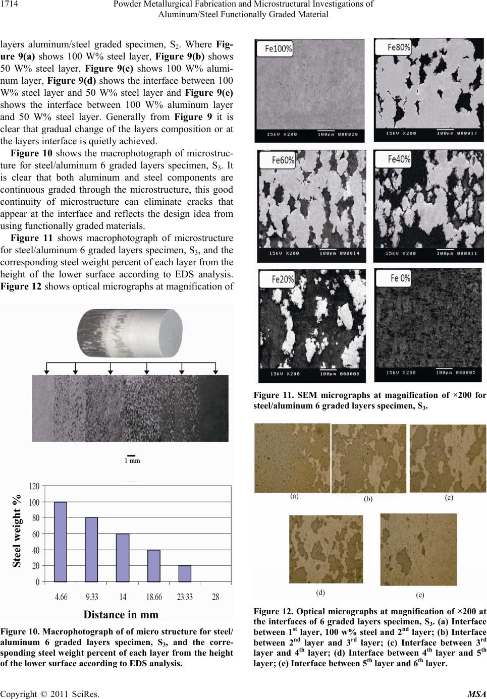 Powder Metallurgical Fabrication and Microstructural Investigations of 1714 Aluminum/Steel Functionally Graded Material layers aluminum/steel graded specimen, S2. Where Fig- ure 9(a) shows 100 W% steel layer, Figure 9(b) shows 50 W% steel layer, Figure 9(c) shows 100 W% alumi- num layer, Figure 9(d) shows the interface between 100 W% steel layer and 50 W% steel layer and Figure 9(e) shows the interface between 100 W% aluminum layer and 50 W% steel layer. Generally from Figure 9 it is clear that gradual change of the layers composition or at the layers interface is quietly achieved. Figure 10 shows the macrophotograph of microstruc- ture for steel/aluminum 6 graded layers specimen, S3. It is clear that both aluminum and steel components are continuous graded through the microstructure, this good continuity of microstructure can eliminate cracks that appear at the interface and reflects the design idea from using functionally grad ed materials. Figure 11 shows macrophotograph of microstructure for steel/aluminum 6 graded layers specimen, S3, and the corresponding steel weight percent of each layer from the height of the lower surface according to EDS analysis. Figure 12 shows optical micr ographs at magnificatio n of Figure 10. Macrophotograph of of micro structure for steel/ aluminum 6 graded layers specimen, S3, and the corre- sponding steel weight percent of each layer from the height of the lower surface according to EDS analysis. Figure 11. SEM micrographs at magnification of ×200 for steel/aluminum 6 graded layers specimen, S3. Figure 12. Optical micrographs at magnification of ×200 at the interfaces of 6 graded layers specimen, S3. (a) Interface between 1st layer, 100 w% steel and 2nd layer; (b) Interface between 2nd layer and 3rd layer; (c) Interface between 3rd layer and 4th layer; (d) Interface between 4th layer and 5th layer; (e) Interface between 5th layer and 6th layer. Copyright © 2011 SciRes. MSA  Powder Metallurgical Fabrication and Microstructural Investigations of 1715 Aluminum/Steel Functionally Graded Material ×200 at the interfaces of 6 graded layers specimen, S3. It is worth to note that the optical micrographs at magnify- cation of ×200 for the different layers of 6 graded layers specimen, S3, are obtained but not shown. From Figures 10-12 it is very interesting to note that increasing the number of layers in specimen increased the interlock between steel and aluminum. Also, it can be seen that there are no defects observed, and smooth gradient dis- tribution from steel to aluminum is successfully obtained Figure 13 shows macrophotograph of microstructures of steel/aluminum 9 graded layers specimen and the cor- responding steel weight percent along the height from the lower surface, 100% steel. It is clear that as the number of layers increases the difference of the composition be- tween layers decreases. Figure 14 shows SEM micro- graphs at magnification of ×200 for steel/aluminum 9 graded layers specimen, S4. Also, from Figure 14 it can be seen that very good gradual change of the basic con- stituents, steel and aluminum, through the layers from 100% steel to 100% aluminum. Figure 15 shows Macrophotograph of microstructures for steel/aluminum 15 graded layers specimen and the corresponding steel weight percent according to EDS analysis along the height, from the lower surface, 100% steel. Figure 13. Macrophotograph of microstructures of steel/ aluminum 9 graded layers specimen and the corresponding steel weight percent according to EDS analysis along the height from the lower surface, 100% steel. Figure 14. SEM micrographs at magnification of ×200 for steel/aluminum 9 graded layers specimen, S4. Also, SEM micrographs at magnification of ×200 for steel/aluminum 15 graded layers specimen, S5 was ob- tained, not shown here. From the above result, it is clear that increasing number of layers will reduce the interface between layers and produce functionally graded material not functionally graded layers. Therefore, steel/aluminum 21 graded layers w ill be adopted as steel/aluminu m func- tionally graded material. Figure 16 shows macrophotograph of microstructures for steel/aluminum graded material specimen, S6, and the corresponding steel weight percent according to EDS Copyright © 2011 SciRes. MSA 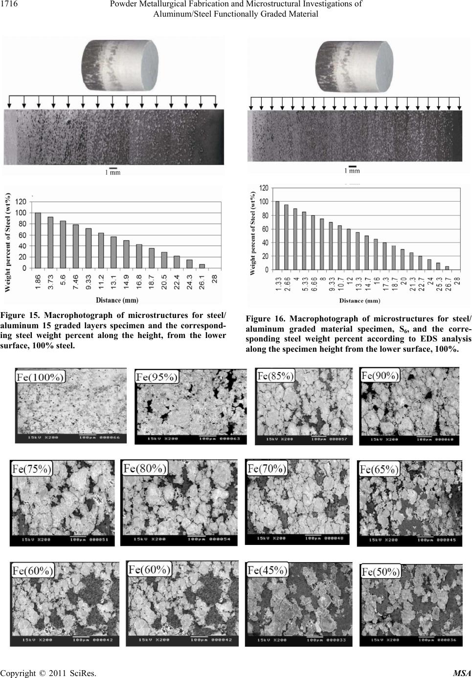 Powder Metallurgical Fabrication and Microstructural Investigations of Aluminum/Steel Functionally Graded Material Copyright © 2011 SciRes. MSA 1716 Figure 15. Macrophotograph of microstructures for steel/ Figure 16. Macrophotograph of microstructures for steel/ aluminum graded material specimen, S6, and the corre- sponding steel weight percent according to EDS analysis along the specimen height from the lower surface, 100%. aluminum 15 graded layers specimen and the correspond- ing steel weight percent along the height, from the lower surface, 100% steel. 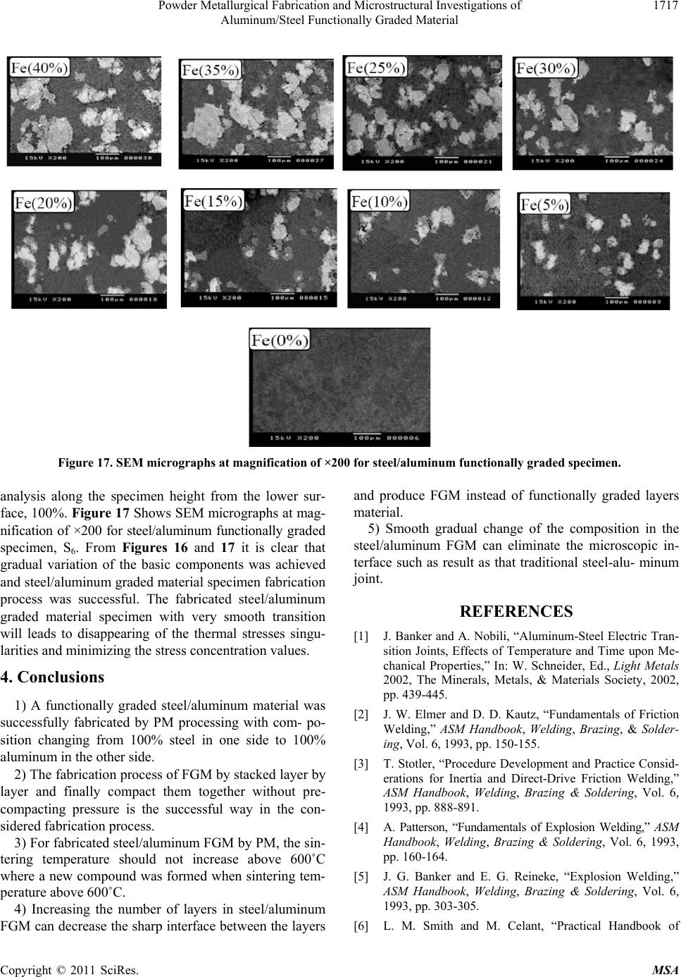 Powder Metallurgical Fabrication and Microstructural Investigations of 1717 Aluminum/Steel Functionally Graded Material Figure 17. SEM micrographs at magnification of ×200 for steel/aluminum functionally graded specimen. analysis along the specimen height from the lower sur- face, 100%. Figure 17 Shows SEM micrographs at mag- nification of ×200 for steel/aluminum functionally graded specimen, S6. From Figures 16 and 17 it is clear that gradual variation of the basic components was achieved and steel/ rocess w y mpact them together without pre- e is the successful way in the con- si and produce FGM instead of functionally graded layers material. 5) Smooth gradual change of the composition in the steel/aluminum FGM can eliminate the microscopic in- terface such hat traditional steel-alu- minum “Aluminum-Steel Electric Tran- dbook, Welding, Brazing & Soldering, Vol. 6, 1993, pp. 160-164. [5] J. G. Banker plosion Welding,” aluminum graded material specimen fabrication as successful. The fabricated steel/aluminum joint. p graded material specimen with very smooth transition will leads to disappearing of the thermal stresses singu- larities and minimizing the stress concentration values. 4. Conclusions 1) A functionally graded steel/aluminum material was successfully fabricated by PM processing with com- po- sition changing from 100% steel in one side to 100% aluminum in the other side. 2) The fabrication process of FGM by stacked layer b layer and finally co compacting pressur dered fabricatio n process. 3) For fabricated steel/alu minum FGM by PM, th e sin- tering temperature should not increase above 600˚C where a new compound was formed when sintering tem- perature above 600˚C. 4) Increasing the number of layers in steel/aluminum FGM can decrease the sharp interface between the layers REFERENCES [1] J. Banker and A. Nobili, as result as t sition Joints, Effects of Temperature and Time upon Me- chanical Properties,” In: W. Schneider, Ed., Light Metals 2002, The Minerals, Metals, & Materials Society, 2002, pp. 439-445. [2] J. W. Elmer and D. D. Kautz, “Fundamentals of Friction Welding,” ASM Handbook, Welding, Brazing, & Solder- ing, Vol. 6, 1993, pp. 150-155. [3] T. Stotler, “Procedure Development and Practice Consid- erations for Inertia and Direct-Drive Friction Welding,” ASM Handbook, Welding, Brazing & Soldering, Vol. 6, 1993, pp. 888-891. [4] A. Patterson, “Fundamentals of Explosion Welding,” ASM Han and E. G. Reineke, “Ex ASM Handbook, Welding, Brazing & Soldering, Vol. 6, 1993, pp. 303-305. [6] L. M. Smith and M. Celant, “Practical Handbook of Copyright © 2011 SciRes. MSA 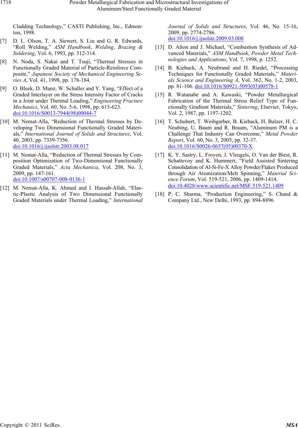 Powder Metallurgical Fabrication and Microstructural Investigations of 1718 Aluminum/Steel Functionally Graded Material ol. 60, No. 5-6, 1998, pp. 615-623. Cladding Technology,” CASTI Publishing, Inc., Edmon- ton, 1998. [7] D. L. Olson, T. A. Siewert, S. Liu and G. R. Edwards, “Roll Welding,” ASM Handbook, Welding, Brazing & Soldering, Vol. 6, 1993, pp. 312-314. [8] N. Noda, S. Nakai and T. Tsuji, “Thermal Stresses in Functionally Graded Material of Particle-Reinforce Com- posite,” Japanese Society of Mechanical Engineering Se- ries A, Vol. 41, 1998, pp. 178-184. [9] O. Bleek, D. Munz, W. Schaller and Y. Yang, “Effect of a Graded Interlayer on the Stress Intensity Factor of Cracks in a Joint under Thermal Loading,” Engineering Fracture Mechanics, V doi:10.1016/S0013-7944(98)00044-7 [10] M. Nemat-Alla, “Reduction of Thermal Stresses by De- veloping Two Dimensional Functionally Graded Materi- /j.ijsolstr.2003.08.017 als,” International Journal of Solids and Structures, Vol. 40, 2003, pp. 7339-7356. doi:10.1016 , No. 3, [11] M. Nemat-Alla, “Reduction of Thermal Stresses by Com- position Optimization of Two-Dimensional Functionally Graded Materials,” Acta Mechanica, Vol. 208 2009, pp. 147-161. doi:10.1007/s00707-008-0136-1 [12] M. Nemat-Alla, K. Ahmed and I. Hassab-Allah, “Elas- tic-Plastic Analysis of Two Dimensional Functionally Graded Materials under Thermal Loading,” International Journal of Solids and Structures, Vol. 46, No. 15-16, 2009, pp. 2774-2786. doi:10.1016/j.ijsolstr.2009.03.008 [13] D. Alton and J. Michael, “Combustion S vanced Materials,” ASM Handboynthesis of Ad- ok, Powder Metal Tech- 3(03)00578-1 nologies and Applications, Vol. 7, 1998, p. 1252. [14] B. Kieback, A. Neubrand and H. Riedel, “Processing Techniques for Functionally Graded Materials,” Materi- als Science and Engineering A, Vol. 362, No. 1-2, 2003, pp. 81-106. doi:10.1016/S0921-509 [15] R. Watanabe and A. Kawaski, “Powder Metallurgical Fabrication of the Thermal Stress Relief Type of Fun- ctionally Gradient Materials,” Sintering, Elsevier, Tokyo, Vol. 2, 1987, pp. 1197-1202. [16] T. Schubert, T. Weibgarber, B. Kieback, H. Balzer, H. C. Neubing, U. Baum and R. Braum, “Aluminum PM is a Challenge That Industry Can Overcome,” Metal Powder Report, Vol. 60, No. 3, 2005, pp. 32-37. doi:10.1016/S0026-0657(05)00370-X [17] K. Y. Sastry, L. Froy en, J. Vleugels, O. Van der Biest, R. Schattevoy and K. Hummert, “Field Assisted Sintering Consolidation of Al-Si-Fe-X Alloy Powder/Flakes Pr od uc ed through Air Atomization/Melt Spinning,” Material Sci- ence Forum, Vol. 519-521, 2006, pp. 1409-1414. doi:10.4028/www.scientific.net/MSF.519-521.1409 [18] P. C. Sharma, “Production Engineering Company Ltd., New Delhi, 1993, pp. 8,” S. Chand & 94-8896 Copyright © 2011 SciRes. MSA
|