Paper Menu >>
Journal Menu >>
 Int. J. Communications, Network and System Sciences, 2010, 3, 418-424 doi:10.4236/ijcns.2010.34054 Published Online April 2010 (http://www.SciRP.org/journal/ijcns/) Copyright © 2010 SciRes. IJCNS Comparative Study of Different Space-Time Coding Schemes for MC-CDMA Systems Lokesh Kumar Bansal1, Aditya Trivedi2 1Department of ECE, Nikhil Institute of Engineering and Management, Mathura, India 2Department of Information and Communication Technology, ABV-Indian Institute of Information Technology and Management, Gwalior, India Email: lokesh_bansal@rediffmail.com, atrivedi@iiitm.ac.in Received January 5, 2010; revised February 9, 2010; accepted March 10, 2010 Abstract In this paper, performance of space-time trellis-code (STTC), space-time block code (STBC), and space-time trellis-code concatenated with space-time block code (STTC-STBC) for multi-carrier code-division multi- ple-access (MC-CDMA) system are studied. These schemes are considered by employing different detection techniques with various multi input multi output (MIMO) antenna diversity for different number of states in multi-path fading channel. The corresponding bit error rate (BER) is obtained using simulation for minimum mean-square error (MMSE), maximum-ratio combining (MRC), and equal-gain combining (EGC) receivers employing Viterbi decoder. The simulation results show that the STTC-STBC MC-CDMA system perform better compared to other schemes considered in this paper using MMSE detection and it is also observed that the performance can also be enhanced by increasing diversity using more transmitter and receiver antennas. However, this improvement in performance comes at the cost of increased computational complexity, which is calculated for different transmitting and receiving antennas. Keywords: Space-Time Code, Space-Time Trellis-Code (STTC), Space-Time Block-Code (STBC), MIMO, MMSE, Multi-Path Channel 1. Introduction Cellular services are now being used every day by mil- lions of people worldwide and the demand is increasing exponentially. Also, there is a demand for integration of a variety of multimedia services namely short messaging, voice, data, and video. Consequently, the bit rate is requ- ired to vary from 1.2 kbps for paging to several Mbps for video transmission. The data rate of the second genera- tion is limited up to 9.6 kbps [1]. The third generation cellular systems are being de- signed to support wideband services like high-speed int- ernet access, video and high quality image transmission with the same quality as the fixed networks. The third generation can provide the maximum data rate ranging from 64 kbps for mobile users to 2 Mbps for stationary users. The drawbacks arising in the third generation sys- tem are the limitations of data rate, capacity, inter sym- bol interference (ISI), and inter chip interference (ICI). For solving the problems of third generation wireless communication systems, and fulfilling the demand of hi- gh performance and broadband internet access with high spectrum efficiency, the fourth generation systems which may employ multi-carrier code-division multiple-access (MC-CDMA) technology in combination with multi-in- put multi-output (MIMO) antennas are proposed [2]. In the fourth generation wireless communication systems the data rate may be as high as 1Gbps. Space-time cod- ing techniques may be employed in conjunction with the MC-CDMA system to achieve very high data rate [3,4]. In this paper, the space-time trellis-code (STTC), spa- ce-time block code (STBC), and space-time trellis-code concatenated with space-time block code (STTC-STBC) techniques are studied and applied in multi-carrier code- division multiple-access (MC-CDMA) systems. These techniques are considered with multi input multi output (MIMO) antenna diversity in multi-path fading channel. The bit error rate (BER) is obtained for 4, 8, and 16 states using simulation. At the receiver side minimum mean- square error (MMSE), maximum-ratio combining (MRC), and equal-gain combining (EGC) techniques are used by employing Viterbi algorithm. The organization of the rest of this paper is as follows: in Section 2, MC-CDMA systems and the space-time 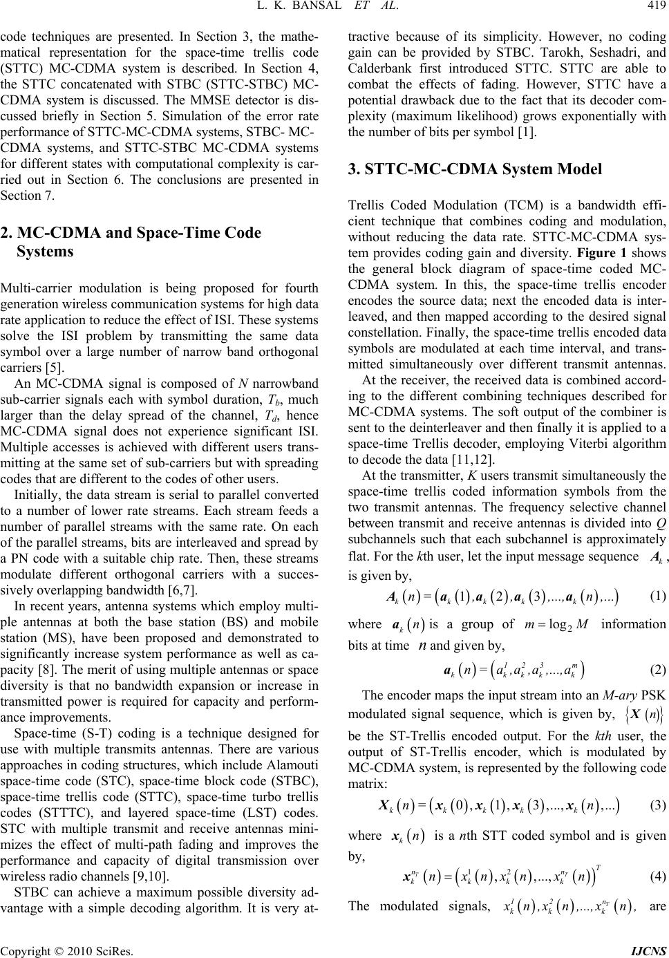 L. K. BANSAL ET AL. 419 code techniques are presented. In Section 3, the mathe- matical representation for the space-time trellis code (STTC) MC-CDMA system is described. In Section 4, the STTC concatenated with STBC (STTC-STBC) MC- CDMA system is discussed. The MMSE detector is dis- cussed briefly in Section 5. Simulation of the error rate performance of STTC-MC-CDMA systems, STBC- MC- CDMA systems, and STTC-STBC MC-CDMA systems for different states with computational complexity is car- ried out in Section 6. The conclusions are presented in Section 7. 2. MC-CDMA and Space-Time Code Systems Multi-carrier modulation is being proposed for fourth generation wireless communication systems for high data rate application to reduce the effect of ISI. These systems solve the ISI problem by transmitting the same data symbol over a large number of narrow band orthogonal carriers [5]. An MC-CDMA signal is composed of N narrowband sub-carrier signals each with symbol duration, Tb, much larger than the delay spread of the channel, Td, hence MC-CDMA signal does not experience significant ISI. Multiple accesses is achieved with different users trans- mitting at the same set of sub-carriers but with spreading codes that are different to the codes of other users. Initially, the data stream is serial to parallel converted to a number of lower rate streams. Each stream feeds a number of parallel streams with the same rate. On each of the parallel streams, bits are interleaved and spread by a PN code with a suitable chip rate. Then, these streams modulate different orthogonal carriers with a succes- sively overlapping bandwidth [6,7]. In recent years, antenna systems which employ multi- ple antennas at both the base station (BS) and mobile station (MS), have been proposed and demonstrated to significantly increase system performance as well as ca- pacity [8]. The merit of using multiple antennas or space diversity is that no bandwidth expansion or increase in transmitted power is required for capacity and perform- ance improvements. Space-time (S-T) coding is a technique designed for use with multiple transmits antennas. There are various approaches in coding structures, which include Alamouti space-time code (STC), space-time block code (STBC), space-time trellis code (STTC), space-time turbo trellis codes (STTTC), and layered space-time (LST) codes. STC with multiple transmit and receive antennas mini- mizes the effect of multi-path fading and improves the performance and capacity of digital transmission over wireless radio channels [9,10]. STBC can achieve a maximum possible diversity ad- vantage with a simple decoding algorithm. It is very at- tractive because of its simplicity. However, no coding gain can be provided by STBC. Tarokh, Seshadri, and Calderbank first introduced STTC. STTC are able to combat the effects of fading. However, STTC have a potential drawback due to the fact that its decoder com- plexity (maximum likelihood) grows exponentially with the number of bits per symbol [1]. 3. STTC-MC-CDMA System Model Trellis Coded Modulation (TCM) is a bandwidth effi- cient technique that combines coding and modulation, without reducing the data rate. STTC-MC-CDMA sys- tem provides coding gain and diversity. Figure 1 shows the general block diagram of space-time coded MC- CDMA system. In this, the space-time trellis encoder encodes the source data; next the encoded data is inter- leaved, and then mapped according to the desired signal constellation. Finally, the space-time trellis encoded data symbols are modulated at each time interval, and trans- mitted simultaneously over different transmit antennas. At the receiver, the received data is combined accord- ing to the different combining techniques described for MC-CDMA systems. The soft output of the combiner is sent to the deinterleaver and then finally it is applied to a space-time Trellis decoder, employing Viterbi algorithm to decode the data [11,12]. At the transmitter, K users transmit simultaneously the space-time trellis coded information symbols from the two transmit antennas. The frequency selective channel between transmit and receive antennas is divided into Q subchannels such that each subchannel is approximately flat. For the kth user, let the input message sequence , is given by, k A 123 kkkkk n =,,,...,n ,...Aaaaa (1) where kna n is a group of information bits at time and given by, Mm 2 log 123 m kkkk n=a ,a,a ,...,aak (2) The encoder maps the input stream into an M-ary PSK modulated signal sequence, which is given by, nX be the ST-Trellis encoded output. For the kth user, the output of ST-Trellis encoder, which is modulated by MC-CDMA system, is represented by the following code matrix: =0,1 ,3,...,,... kkkkk nnXxxxx (3) where knx is a nth STT coded symbol and is given by, 12 , ,..., TT T nn kkkk nxnxn xnx (4) T n 12 kk k x n ,xn ,...,xn , are The modulated signals, Copyright © 2010 SciRes. IJCNS 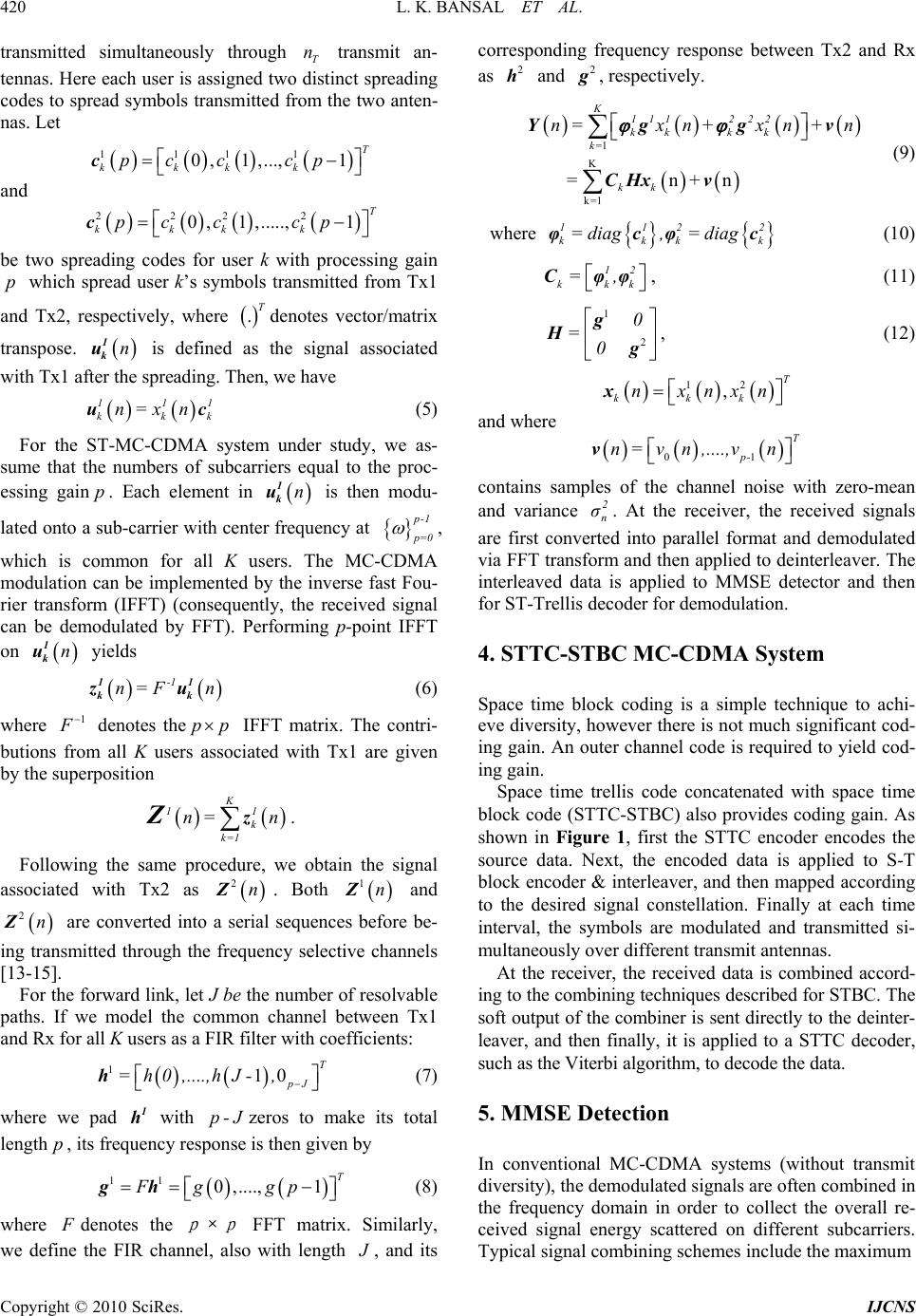 420 L. K. BANSAL ET AL. through transmit and be two ading codes for user k withocessing gain ter the (5) For the ST-MC-CDMA su transmitted simultaneously an- tennas. Here each user is assigned two dtinct spreading codes to spread symbols transmitted from the two anten- nas. Let T n is c c pr qu 1111 0,1 ,...,1T kkkk pc cp c 222 2 0,1,.....,1T kkk k pc cp c spre p which spread user k’s symbols transmitted from Tx1 d Tx2, respectively, where .Tdenotes vector/matrix transpose. n 1 k u is defined as the signal associated with Tx1 af spreading. Then, we have 111 kkk n=x nuc an system under study, we as- me that the numbers of subcarriers equal to the proc- essing gainp. Each element in n 1 k u is then modu- lated onto a b-carrier with centerency at su fre p -1 p =0 , which is common for all K users. The MC-C modulation can be implemented by the inverse fast Fou- rier transform (IFFT) (consequently, the received signal can be demodulated by FFT). Performing p-point IFFT on n 1 k u yields n= 1 kk z DMA -1 F nu 1 (6) where 1 F denotes the froasso Following the same procedurthe signal as pp IFFT matrix. The contri- butionsm all K users ciated with Tx1 are given by the superposition 1 Z K 1 k k=1 n= n z. e, we obtain sociated with Tx2 as 2nZ. Both 1nZ and 2nZ are converted into asequencee be- nsmitted through the frequency selective channels [13-15]. For the forward link, let J be the number of resolvable pa serial s befor ing tra 7) where we pad with zeros (8) where ths. If we model the common channel between Tx1 and Rx for all K users as a FIR filter with coefficients: 110 T pJ =h0,....,hJ-, h ( 1 h e p-J onse to make its total length p, its frequncy resp is then given by 11 0 ,....,1T Fg gp gh F denotes the pp × FFT ix we defithe FIR cha matr with length . Similarly, , and its oncy respcorrespding frequenonse between Tx2 and Rx as 2 h and 2 g , respectively. K 111 kk =x n Yg ne nnel, also J 1 =n+n 2 22 k k kk n+xn +ng CHx v K k= 1 k= v (9) we her 112 kkk ag,=diagφcφc 2 k (10) =di kk 12 k =, Cφφ , (11) 1 2 0 =0 Hg g , (12) kk k n 12 ,T xnxn x and where 01p- n =vn ,....,vn T v p n σ r y, ho (STTC he contains sam and va e dive versit les of the channel noise with zero-mean riance. At the receiver, the received signals m m to achi- rsitwever there is not much significant cod- -STBC) also provides coding gain. As sh BC. The so A systems (without transmit iy), tdemodulated signals are often combined in Typical signal combining schemes include the maximum 2 are first converted into parallel format and demodulated via FFT transfo and then applied to deinterleaver. The interleaved data is applied to MMSE detector and then for ST-Trellis decoder for demodulation. 4. STTC-STBC MC-CDMA Syste Space time block coding is a simple technique ev ing gain. An outer channel code is required to yield cod- ing gain. Space time trellis code concatenated with space time block code own in Figure 1, first the STTC encoder encodes the source data. Next, the encoded data is applied to S-T block encoder & interleaver, and then mapped according to the desired signal constellation. Finally at each time interval, the symbols are modulated and transmitted si- multaneously over different transmit antennas. At the receiver, the received data is combined accord- ing to the combining techniques described for ST ft output of the combiner is sent directly to the deinter- leaver, and then finally, it is applied to a STTC decoder, such as the Viterbi algorithm, to decode the data. 5. MMSE Detection In conventional MC-CDM d the frequency domain in order to collect the overall re- ceived signal energy scattered on different subcarriers. Copyright © 2010 SciRes. IJCNS 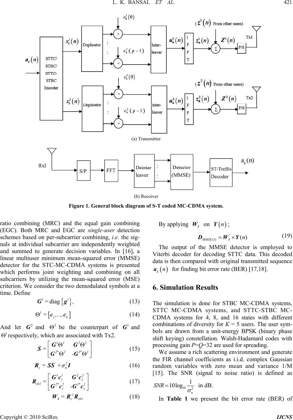 L. K. BANSAL ET AL. 421 Copyright © 2010 SciRes. IJCNS (a) Transmitter (b) Receiver Figure 1. General block diagrcoded MC-CDMA system. ratio combining (MRC) an GC). Both MRC and EGC are single-user detection am of S-T nY d the equal gain combining By applying on 1 W; (E ( 1 ) () M MSE n ' 1 DWY (19) The output of the MMSE detect Viterbi decoder for decoding ST data is then compared with origin schemes based on per-subcarrier combining, i.e. the sig- nals at individual subcarrier are independently weighted and summed to generate decision variables. In [16], a linear multiuser minimum mean-squared error (MMSE) detector for the STC-MC-CDMA systems is presented which performs joint weighting and combining on all subcarriers by utilizing the mean-squared error (MSE) criterion. We consider the two demodulated symbols at a time. Define 11 diag= ,G g (13) or is employed to TC data. This decoded al transmitted sequence kn for findibit erre (B ang or ratER) [17,18]. 6. Simulation Results CDMAfferent mbinations of diversity for K = 5 users. The user sym- energy BPSK (binary phase Walsh-Hadamard codes with The simulation is done for STBC MC-CDMA systems, STTC MC-CDMA systems, and STTC-STBC MC- systems for 4, 8, and 16 states with di 1 1k = ,...,cc (14) co And let and be t (15) 2 G2 he counterpart of 1 Gand bols are drawn from a unit- ift keying) constellation. 1 respectively, which are associated with Tx2. 1 22 2*21* 1 =- G SGG sh 1 Gprocessing gain P=Q=32 are used for spreading. We assume a rich scattering environment and generate the FIR channel coefficients as i.i.d. complex Gaussian random variables with zero mean and variance 1/M [15]. The SNR (signal to noise ratio) is defined as '2 z n =+σ R SSI (16) 11 1 zb1 2*21* 1 11 =- Gc RGcGc 2 2 1 Gc (17) 10 2 1 10log n SNR in dB. -1 z zb1 = 1 WRR (18) In Table 1 we present the bit error rate (BER) of 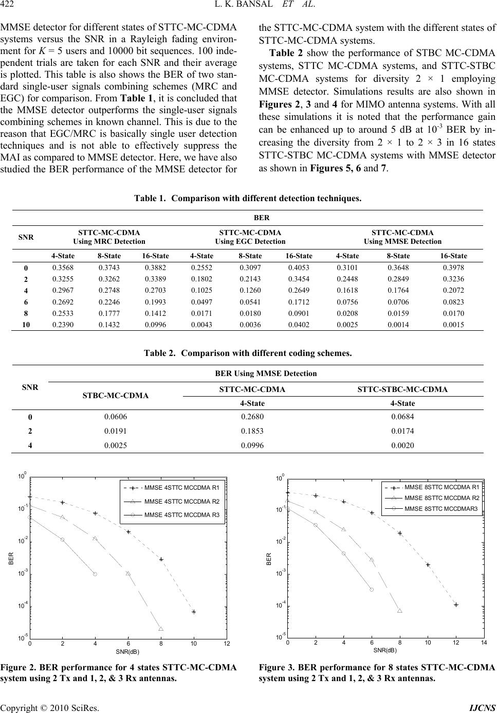 422 L. K. BANSAL ET AL. pendent trials are taken for each SNR and their average is plotted. This taows the BER of two stan- dard single-usersity 2 × 1 employing M iff BER MMSE detector for different states of STTC-MC-CDMA systems versus the SNR in a Rayleigh fading environ- ment for K = 5 users and 10000 bit sequences. 100 inde- ble is also sh er signals combining schemes (MRC and EGC) for comparison. From Table 1, it is concluded that the MMSE detector outperforms the single-user signals combining schemes in known channel. This is due to the reason that EGC/MRC is basically single user detection techniques and is not able to effectively suppress the MAI as compared to MMSE detector. Here, we have also studied the BER performance of the MMSE detector for the STTC-MC-CDMA system with the different states of STTC-MC-CDMA systems. Table 2 show the performance of STBC MC-CDMA Table 1. Comparison with d systems, STTC MC-CDMA systems, and STTC-STBC MC-CDMA systems for div MSE detector. Simulations results are also shown in Figures 2, 3 and 4 for MIMO antenna systems. With all these simulations it is noted that the performance gain can be enhanced up to around 5 dB at 10-3 BER by in- creasing the diversity from 2 × 1 to 2 × 3 in 16 states STTC-STBC MC-CDMA systems with MMSE detector as shown in Figures 5, 6 and 7. erent detection techniques. SNR STTC-MC-CDMA Using MRC Detect STTC-MC-CDMA STTC-MC-CDMA g MMSE Detection ion Using EGC Detection Usin 4-State 8-State 16-State 4-State 8-StaState 4-State 8-State 16-State te 16- 0 0.3568 0.3743 0.3882 0.2552 0.30 0.4053 0.3101 0.3648 0.3978 97 2 0.3255 3389 0.1802 0.3454 0.2448 3236 4 0.2967 2703 0.1025 2649 0.1618 2072 0. 0.2748 0. 0.3262 0.2143 0.2849 0. 0.1764 0. 0.1260 0. 6 0.2692 0.2246 0.1993 0.0497 0.0541 0.1712 0.0756 0.0706 0.0823 8 0.2533 0.1777 0.1412 0.0171 0.0180 0.0901 0.0208 0.0159 0.0170 10 0.2390 0.1432 0.0996 0.0043 0.0036 0.0402 0.0025 0.0014 0.0015 . Cson werent sche E D Table 2ompariith diff codingmes. BER Using MMSetection STTC-MC-CDMA STTC-STBC-MC-CDMA SNR STBC-MC-CDM 4-State A 4-State 0 0.0606 0.0684 0.2680 2 0.0191 4 0.1853 0.0174 0.0025 0.0996 0.0020 0 2 46 810 12 10 -5 10 -4 10 -3 10 -2 10 -1 10 0 SNR(dB) BER MMSE 4STTC MCCDMA R1 MMSE 4STTC MCCDMA R2 MMSE 4STTC MCCDMA R3 0246810 12 14 10 -5 10 -4 10 -3 10 -2 10 -1 10 0 SNR(dB) BER MMSE 8STTC MCCDMA R1 MMSE 8STTC MCCDMA R2 MMSE 8STTC MCCDMAR3 Figure 3. BER performance for 8 states STTC-MC-CDMA system using 2 Tx and 1, 2, & 3 Rx antennas. Figure 2. BER performance for 4 states STTC-MC-CDMA system using 2 Tx and 1, 2, & 3 Rx antennas. Copyright © 2010 SciRes. IJCNS  L. K. BANSAL ET AL. 423 0 2 46 81012 10 -5 10 -4 10 -3 10 -2 10 -1 10 0 SNR(dB) BER MMSE 16STTC MCCDMA R1 MMSE 16STTC MCCDMA R2 MMSE 16STTC MCCDMA R3 Figure 4. BER performance for 16 states STTC-MC-CD- MA system using 2 Tx and 1, 2, & 3 Rx antennas. 0246810 12 14 10 -5 10 -4 10 -3 10 -2 10 -1 10 0 SNR(dB) BER MMSE 4STTC MCCDMA R2 MMSE 8STTC MCCDMA R2 MMSE 16STTC MCCDMA R2 Figure 5. BER performance for 4, 8, & 16 states STTC-MC- CDMA system using 2 Tx and 2 Rx antennas. 0123456 10 -6 10 -5 10 -4 10 -3 10 -2 10 -1 SNR(dB) BER MMSE 4STTC-STBC MCCDMA R3 MMSE 8STTC-STBC MCCDMA R3 MMSE 16STTC-STBC MCCDMA R3 re 6. BER performance for 4, 8, & 16 states STTC- STBC MC-CDMA system using 2 Tx and 3 Rx antennas. Figu 0 1 2345 6 78910 10 -5 10 -4 10 -3 10 -2 10 -1 10 0 SNR(dB) BER MMSE 16STTC-STBC MCCDMA R1 MMSE 16STTC-STBC MCCDMA R2 MMSE 16STTC-STBC MCCDMA R3 Figure 7. BER performance of 16 states STTC-STBC MC- CDMA system using 2 Tx and 1, 2, & 3 Rx antennas. 6.1. Computational Complexity Calculations Computational complexity in decoding is an important issue. Viterbi algorithm is used to decode the actual trel- lis codeword. The numeric computational complexity involved is calculated as follows. Consider L= 2v is the number of states where v is the number of delay elements in the STTC encoder. The number of operations for multiplication/division are { 12 L RT nn tions/ subtract }, comparisons are {}, and addi- ions are {2 21 L 1] [1 L RT nn ber of transm }. it It may be is the numting and noted that T n R n is the number of receiving antennas. For example the numeric computational complexity for 4 states, 2 transmitter and 2 receiver antennas are: Multiplication/Division are = 12 L RT nn=96; (20) Comparisons are == 15; (21) & Addition/Subtraction are = ]2 21 L [11 L RT nn = 80 (22) Compare to one receive antenna the no. of multiplica- tion/division operations involved are two times (as evi- dent from Equation (20)). However, the improvement in the performance is approximately 2 dB at 10-3 probability of error employing MMSE detection as shown in the simulation results. This demonstrates the tradeoff in- volved in computational complexity and performance improvement. this paper, BER performance for STBC-MC-CDMA 7. Conclusions In Copyright © 2010 SciRes. IJCNS  424 L. K. BANSAL ET AL. Copyright © 2010 SciRes. IJCNS BC C-CDMA systems is evaluated using simulation for r sc l the schemeease ty. In particular, S ity wned in this paper. 8. References erbank, “Space- rate Wireless Communication: Performance Criterion and Code Const Transactions on Information Theory, Vol. 44 Natarajan and Z. Wu., “Flexible Spectrum Coexistence at the Physical Layer of stems via a Multicarrier Platform,” IEEE Wireless Communication, April 2004, pp. 64-71. ance Enhancement of Multiuser MIMO Wireless Commu- s,” IEEE Transactions on Communications, December 2002, pp. 1960-1968. E Pro- e Channels,” IEEE Proceedings, 2001, pp. 868-872. e- . K. Bansal, “Performance Study of systems, STTC-MC-CDMA systems, and STTC-ST M different states in known channel environment. For sig- nal detection MMSE, MRC, and EGC receivers are con- sidered. The simulation results are presented for the evaluation of the multi transmit multi receive antenna systems employing Viterbi decoding. It is noted that the performance of STTC–STBC MC-CDMA system using MMSE detector is better than othehemes considered in this paper. Performance of als improves with the incr in number of states and antenna diversi it is observed that STTC-STBC MC-CDMA systems using MMSE detector gives advantage of around 5 dB in terms ofNR while increasing diversity from 2 × 1 to 2 × 3, 16 states and at 10-3 BER. This improvement in performance is no computational complexted at the cost of increased hich is calculated and mentio Rim [1] V. Tarokh, N. Seshadri and A. R. Cald Time Codes for High Data cee ruction,” IEEE , No. 2, March 1998, pp. 744-765. [2] H. Sampath, S. Talwar and J. Tellado, “A Fourth Genera- tion MIMO-OFDM Broadband Wireless System: Design, Performance, and Field Trial Results,” IEEE Communi- cation Magazine, September 2002, pp. 143-149. [3] M. Juntti, M. Vehkapera, J. Leinonen, “MIMO MC-CD- MA Communications for Future Cellular Systems,” IEEE Communication Magazine, Feburary 2005, pp. 118-124. ] S. Hijazi, B.[4 Fuuse and Better ture Wireless Sy -[16] L. A. P. Hernandez and M. G. Otero, “A New STB-TCM Coded MC-CDMA Systems with MMSE-SVA Based Decoding and Soft-Interference Cancellation,” IEEE Proceedings, 2005, pp. 113-116. [17] A. Trivedi and L [5] E. A. Sourour and Masao Nakagawa, “Performance of Orthogonal Multicarrier CDMA in a Multipath Fading Channel,” IEEE Transactions on Communications, Vol. 44, No. 3, March 1996, pp. 356-366. [6] S. Hara and R. Prasad, “An Overview of Multi-Carrier CDMA,” IEEE Communication Magazine, Vol. 35, No. 12, December 1997, pp. 126-133. [7] S. L. Miller and B. J. Rainbolt, “MMSE Detection of Multicarrier CDMA,” IEEE Journal on Selected Areas in Communications, Vol. 18, No. 11, November 2000, pp. 2356-2362. [8] K. K. Wong, R. D. Murch and K. B. Letaief, “Perform nication System Vol. 50, No. 12, [9] A. F. Naguib, V. Tarokh, N. Seshadri and A. R. Calderb- ank, “A Space-Time Coding Modem for High-Data-Rate Wireless Communications,” IEEE Journal on Selected Areas in Communication, Vol. 16, No. 8, October 1998, pp. 1459-1478. [10] S. M. Alamouti, “A Simple Transmit Diversity Tech- nique for Wireless Communications,” IEEE Journal on Selected Areas in Communications, Vol. 16, No. 8, Oc- tober 1998, pp. 1451-1458. [11] A. Trivedi and M. Bansal, “Adaptive Equalization of Space-Time Coded MC-CDMA Systems,” Communica- tion, Computers and Signal Processing, IEEE Pacific , 22-24 August 2007, pp. 186-189. [12] W. Sun, H. B. Li and M. Amin, “A Subspace-Based Channel Identification Algorithm for Forward Link in Space-Time Coded MC-CDMA Systems,” IEE dings, 2002, pp. 445-448. [13] F. S. Ostuni, M. R. Nakhai and H. Aghvami, “Iterative Multi-User MMSE Receiver for Space-Time Trellis Co- ded CDMA over Frequency Selectiv 14th International Symposium on Personal, Indore and Mobile Radio Communication Proceedings, Chennai 2003, pp. 1968-1972. [14] D. Mottier, D. Castelain, J. F. Helard and J. Y. Baudais, “Optimum and Sub-Optimum Linear MMSE Multi-User Detection for Multi-Carrier CDMA Transmission Sys- tems,” IEEE [15] Wei Sun, Hongbin Li and Moeness Amin, “MMSE D tection for Space-Time Coded MC-CDMA,” IEEE In- ternational Conference on Communications, Cape Town, Vol. 5, No. 11-15, May 2003, pp. 3452-3456. Space-Time Trellis Coded MC-CDMA System Employ- ing Different Detection Techniques,” IEEE Proceedings, World Championship Sports Network, Conducted by In- dian Institute of Information Technology, Allahabad, December 27-29, 2008, pp. 137-140. [18] A. Trivedi and L. K. Bansal, “Comparative Study of Space-Time Trellis Code Concatenated with Space-Time Block Code MC-CDMA System,” IEEE Proceedings, International Anti Corruption Conference, Conducted by Thapar University, Patiala, March 6-7, 2009, pp. 1099-1102. |