Paper Menu >>
Journal Menu >>
 Int. J. Communications, Network and System Sciences, 2010, 3, 395-401 doi:10.4236/ijcns.2010.34050 Published Online April 2010 (http://www.SciRP.org/journal/ijcns/) Copyright © 2010 SciRes. IJCNS Radio Frequency Modelling for Future Wireless Sensor Network on Surface of the Moon Jayesh P. Pabari1, Yashwant B. Acharya1, Uday B. Desai2, Shabbir N. Merchant3, Barla Gopala Krishna4 1PLANEX, Physical Research Laboratory, Ahmedabad, India 2Indian Institute of Technology, Hyderabad, India 3Indian Institute of Technology Bombay, Mumbai, India 4Space Application Centre, Ahmedabad, India Email: jayesh@prl.res.in Received January 6, 2010; revised February 8, 2010; accepted March 10, 2010 Abstract In order to study lunar regolith properties, wireless sensor network is planned to be deployed on surface of the Moon. This network can be deployed having few wireless sensor nodes capable of measuring soil prop- erties and communicating results, as and when ready. Communication scenario on lunar surface is quite dif- ferent as compared to that on the Earth, as there is no atmosphere and also there are lots of craters as well as various terrain topologies. Since the deployment of sensors on the Moon is a challenging and difficult task, it is advisable to predict the behaviour of communication channel on lunar surface. However, communication models like Irregular Terrain Model used for terrestrial communication networks are not directly applicable for Unattended Ground Sensor type sensor networks and need modifications according to lunar surface con- ditions and lunar environment. Efforts have been put to devise a model of radio frequency environment on the Moon using basic equations governing various physical phenomena occurring during radio propagation. The model uses Digital Elevation Model of four sites of the Moon, measured by Terrain Mapping Camera on board Chandrayan-1, a recent Indian mission to the Moon. Results presented in this paper can provide under- standing of percentage area coverage for given minimum received signal strength, potential sites for sensor deployment assuring wireless communication, decision whether a given sensor node can work and can pro- vide suggestion for possible path of rover with cluster head to remain in contact with the nodes. Digital Ele- vation Model based results presented here can provide more insight in to the communication scenario on the Moon and can be very useful to mission planners. Keywords: Wireless Model, Moon, DEM, Coverage 1. Introduction In order to detect few regolith properties on lunar sur- face, a Wireless Sensor Network (WSN) is planned to be deployed near lunar South Pole, which utilizes wir- eless sensors capable of working in harsh environ- mental conditions. Main property of interest is permit- tivity obtainable from impedance sensor. Since the de- ployment of network on the Moon is a challenging and difficult task, it is advisable to predict the behaviour of communication channel on the lunar surface by some channel model. There have been various models for radio commu- nication on the Earth, for example Irregular Terrain Model (ITM) also known as Longley-Rice model given by G. Hufford, A. Longley and W. Kissick [1] and model given by Durkin [2,3]. ITM is a good model for terrestrial communication network and it uses mini- mum antenna height as 0.5 m for simulation while Durkin’s model does not consider multipath effect in the simulation. Hata [4] had proposed an empirical formulation of graphical path loss valid from about 150 MHz to 1500 MHz and it was extended up to 2 GHz. Walfisch and Bertoni [5] gave a model to consider im- pact of rooftops and building height by using diffrac- tion to predict average signal strength at street level. Alberto Cerpa et al. [6] describes statistical model of lossy links in wireless sensor networks. S. Willis and C. J. Kikkert [7] have given radio propagation model for long range wireless sensor networks. Chirag Patel [8]  396 J. P. PABARI ET AL. has described wireless channel modeling in his thesis. Vishwanath Chukkala et al. [9] and Anirudh Daga et al. [10] gave modeling and simulation of Radio Frequency (RF) environment of Mars. In case of present application scenario, operating fre- quency is to be 2.4 GHz and sensors are to be deployed on lunar surface, where operating conditions are dif- ferent than that on the Earth. It is known that there is no atmosphere on the Moon and there exists very high vacuum of the order of 10-12 Torr [11,12]. The com- munication models used for terrestrial communication networks are not directly applicable to Unattended Ground Sensor (UGS) type sensor network, like that planned on the Moon and need modification according to lunar surface condition. This has motivated us to carry out the work presented in this paper. Efforts have been put to derive modeling of radio frequency envi- ronment on the Moon, using basic equations governing various physical phenomena occurring during radio propagation. Our work uses Digital Elevation Model (DEM) of four sites of the Moon, measured by Terrain Mapping Camera (TMC) on board Chandrayan-1, a recent Indian mission to the Moon. Results presented in this paper can provide understanding of percentage area coverage for given minimum received signal strength, potential sites for sensor deployment assuring wireless communication, decision whether a given sen- sor node could be used and suggestion for possible path of rover (carrying cluster head) to remain in con- tact with the nodes. Section 2 presents suitability of existing propagation models for lunar application, Section 3 describes phy- sical phenomena which can occur on the Moon and as- sociated path losses, Section 4 gives lunar wireless model, Section 5 gives details of DEM of selected sites on lunar surface, Section 6 shows results and paper ends with conclusion. 2. Suitability of Existing Propagation Models for Lunar Application It is expected that the communication would be better on the Moon as compared to that on the Earth, due to absence of atmosphere on the Moon. Few existing pro- pagation models were developed for communication on the Earth and need to be reviewed for the Moon in view of their applicability. 2.1. Irregular Terrain Model Irregular Terrain Model (ITM) was suggested by Rice et al. [13] and is also known as Longley-Rice model. Hufford [14] informed that it can be used in area predic- tion mode and point-to-point mode. ITM takes terrain and other parameters as input and produces output as signal distribution in a given area. There are certain limitations of ITM that it can be used for minimum an- tenna height of 0.5 metre and minimum distance for communication as 1 km. The Point-To-Point (PTP) model given by Wong [15] is based on Longley-Rice model. However, PTP model describes method to obtain diffraction loss. As the wireless sensor network involves deployment of sensors on the ground with very small antenna heights especially at 2.4 GHz operating fre- quency, the ITM can’t be used for such applications. 2.2. Two-Ray Model For a line-of-sight communication, a two-ray model was given by Neskovic et al. [16]. This theoretical model incorporates reflection by the reflection coefficient, which is calculated from incidence angle, dielectric con- stant, surface conductivity and polarization of antenna. The signal strength at the receiver as given in (1) is shown in Willis [7] using free space loss and reflection. 22 12 212 11 |exp()()exp() | 16 ttr r PG Gλ Pjkdψjkd dd π (1) where and are lengths of first and second path respectively. The two ray model is mostly used for direct and ground reflected rays. In case of lunar wireless sensor net- work, sensor nodes are to be the surface with very small antenna heights and therefore ground reflected signal is not expected at the receiver. 1 d2 d 2.3. VSS Multipath Model Signals reflected from reflectors would reach the receiver with different strengths and phases with reference to di- rect signal. At receiver, equivalent signal strength is equ- al to superposition of varying amplitude and phase sig- nals and it is possible to get overall signal strength as reduced or improved. The multipath channel model in AWR Visual System Simulator [17] uses Equations (2) and (3) to obtain signal strength for a sample k. The mul- tipath model was implemented by Willis [18] in MAT- LAB. 1 () (,) N i x kpathk i (2) 2 (,)( )exp() ci ii jπVf Cosθ path kiAx kdC (3) where () x k is kth sample, is number of multipath signals, N (,) p ath k i is contribution of ith multipath sig- nal determined by (3), i A is gain of ith path, () i x kd Copyright © 2010 SciRes. IJCNS  J. P. PABARI ET AL. 397 is delayed sample associated with path and exponen- tial term represents doppler shift due to receiver move- ment. This model may be used for moving nodes, which is not the case for lunar wireless sensor network. i 2.4. Multipath Signal Distribution Instantaneous receiver signal strength (envelope) is rep- resented by either Rayleigh or Rician distribution as sho- wn by Hernando et al. [19]. Rayleigh distribution con- siders only multipath components available and does not take direct path. However, Rician distribution considers direct as well as multipath components. Communication on lunar surface is expected to be line-of-sight and also multipath due to reflections from terrain and therefore, Rician distribution is more suited for lunar application. Rician distribution is shown by Hernando et al. [19] and given below: 22 0 22 ()exp[]( 2 2 rr a pr I σσ ) ra σ for 0r (4) where 0 I is modified 0th order Bessel function and va- lue of depends on direct component. The Rician fun- ction is usually expressed in terms of carrier-to-multipath ratio or factor as a k 2 2 2 ca kmσ (5) where and are strengths of carrier and multipath components respectively. As increases, received sig- nal strength increases and for larger values of , becomes Gaussian. c m k k()pr 2.5. Willis Multipath Model Willis [18] has given extended version of two ray model as multipath model, shown in Equation (6) for terrestrial application on the Earth. 2 2 2 nndn 1 1 111d 2 2 rtt r |)jkdexp( d 1 )(L ...)jkdexp( d 1 )(L| 16 GGP P (6) 3. Physical Phenomena and Path Loss on the Lunar Surface Since the Earth based model cannot be directly used for lunar applications, we have examined various physical phenomena occurring during wave propagation in gen- eral and those applied to wave propagation on the Moon. Such phenomena and losses associated with them are given below and we have combined them to arrive at the path loss given in Section 4. 3.1. Free Space Loss The plan is to use compact wireless impedance sensors (along with other types of sensors) for detection of elec- trical properties of lunar Regolith having small size quarter wave antenna (3.125 cm). The idea is to use line of sight propagation technique for small distances of up to few hundred metres. Under ideal communication con- ditions, the power radiated from antenna is omni direc- tional in the plane of interest, which is horizontal here and power is inverse square function of the distance for free space wave propagation given below [19] by Friis formula. 2 22 16 ttr r PG G λ P πd (7) where and are transmitter and receiver powers, and are gains of transmitter and receiver anten- nas, t P G r P t Gr λ is wavelength of operation and is distance from the transmitter. Free space loss is a basic loss for communication on the lunar surface, since there is a vacuum on the Moon. d 3.2. Reflection For communication on the Earth, there can be factors like steady and moving reflectors and scatterers, atmos- pheric absorption etc and can lead to multipath compo- nents at the receiver. Due to multipath components, sig- nal strength can vary at the receiver due to moving scat- terers. However, in case of lunar application, there are no moving objects on the surface and therefore there can be multipath signals at the receiver due to surface topogra- phy, but received signal strength is not expected to vary randomly due to steady terrain, but it can show periodic variations due to signals travelling in different time dura- tions. Also, there is no atmosphere on the Moon and therefore there are no atmospheric losses, which are pre- sent on the Earth. The main possibility of signal getting affected is that of the surface reflections due to uneven terrain structure. This can cause multipath propagation and signal reaching at the receiver by direct path will be modified due to multipath components. The expected nu- mber of multipath components is few as the mission lan- der should land on comparatively plane or smooth sur- face, where rover can move easily. The wavelength of signal is 12.5 cm at 2.4 GHz wireless operation and ob- jects should be of larger size to cause the reflection. Par- sons [20] derived the received signal strength using re- flection coefficient () from the reflector as given below. Copyright © 2010 SciRes. IJCNS  398 J. P. PABARI ET AL. 22 22|1exp( )| 16 tt r r PG Gλ P πd j (8) where 2 2 ()cos ()cos r r aSinψεjx ψ aSinψεjx ψ is reflection coefficient = phase shift created due to reflected signal a = 1 or for horizontal or vertical polari- zation respectively ( r εjx) ψ = angle of incidence with vertical from transmitter antenna to the reflector r ε = relative dielectric constant of the ground 0 2 σ xπfε σ= conductivity of the ground f = frequency of operation 0 ε= free space permittivity It is also possible to calculate received signal strength by the Equation (9) given by Hernando et al. [19] de- rived from two ray model for longer link distances and lower antenna heights at both ends having direct visibil- ity of each other. 22 4 ttrt r r PG Ghh P d (9) where and are heights of transmitter and receiver antennas respectively. However, for sensors being on surface, Equation (9) may not be used. Reflections are expected from nearby ground terrain on the Moon. Infact the major component for channel fading on the Moon is due to multipath created by reflections from craters and surface irregularities. Also, transceiver used for ground sensors should not use horizontal polarization; otherwise signal would be attenuated [21] very near the transmitter. Instead, vertical polarization should be used, which can provide sufficient signal at farther distances. t hr h 3.3. Reflection Scattering When signal is reflected from lunar surface, it is likely that the ray may be scattered due to dispersed signal. Gibson [22] has suggested this specular reflection and stated that roughness of a surface can be classified by Rayleigh criterion given below: 8cos c i λ hθ (10) where is angle of incidence at the reflector. Gibson [22] gave a parameter , which represents minimum to maximum deviation about mean terrain height. If , then terrain is considered as rough terrain and the loss for it is considered by multiplying reflection coefficient by a scattering loss factor i θ h c hh s ρ calculated by Bothias’ equa- tion as below: 22 0 cos hi θcos exp[8( )][8( )] hi s πσπσ θ ρI λλ (11) where is standard deviation of surface height about the mean surface height and h σ 0 I is the 0th order Bessel function of the first kind. On the lunar surface, the re- gions are mostly rough and may have varying sized ob- jects, which can lead to scattering losses. 3.4. Diffraction For line of sight communication, if an obstacle of size comparable to wavelength is present in between trans- mitter and receiver, then diffraction loss can occur at the edge of an obstacle. The signal may be scattered and at- tenuated before reaching to the receiver. Diffraction from knife-edge obstacle can cause signal to bend and Wong [15] stated that bending of signal due to knife-edge obsta- cle causes higher signal strength as compared to that due to rounded. On the lunar surface it is likely to have such obstacles in between transmitter and receiver, which may be considered only for direct path but the deployment is supposed to be in almost plane terrain for smooth move- ment of the rover and hence possibility of occurrence of such loss is rare and may be neglected. 4. Lunar Wireless Model Equation (6) given by Willis [18] does not include possi- bility of direct path, but it is expected to be present in case of wireless sensor networks. Also, diffraction loss given by Wong [15] may be considered for direct path from transmitter to receiver and not for multipath for operation at 2.4 GHz frequency. Considering diffraction loss only for direct path and including reflection scatter- ing loss factor, following equation is given for obtaining area coverage by wireless sensor network on the lunar surface: 2 2 11 11 22 22 2 1 |exp() 16 () xp() (xp() ... () exp()| ttr dd d s s sn nnn PG Gλjkd d π ρψ jkd ρψ jkd ρψ jkd 1 2 1e 1 ) e 1 rd n PL d d d (12) Copyright © 2010 SciRes. IJCNS 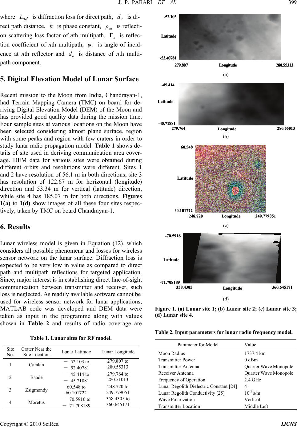 J. P. PABARI ET AL. 399 where is diffraction loss for direct path, is di- dd Ld d rect path distance, is phase constant, k s n ρ is reflecti- on scattering loss factor of nth multipath, is reflec- tion coefficient of nth multipath, is angle of incid- ence at nth reflector and is distance of nth multi- path component. n n ψ n d 5. Digital Elevation Model of Lunar Surface Recent mission to the Moon from India, Chandrayan-1, had Terrain Mapping Camera (TMC) on board for de- riving Digital Elevation Model (DEM) of the Moon and has provided good quality data during the mission time. Four sample sites at various locations on the Moon have been selected considering almost plane surface, region with some peaks and region with few craters in order to study lunar radio propagation model. Table 1 shows de- tails of site used in deriving communication area cover- age. DEM data for various sites were obtained during different orbits and resolutions were different. Sites 1 and 2 have resolution of 56.1 m in both directions; site 3 has resolution of 122.67 m for horizontal (longitude) direction and 53.34 m for vertical (latitude) direction, while site 4 has 185.07 m for both directions. Figures 1(a) to 1(d) show images of all these four sites respec- tively, taken by TMC on board Chandrayan-1. 6. Results Lunar wireless model is given in Equation (12), which considers all possible phenomena and losses for wireless sensor network on the lunar surface. Diffraction loss is expected to be very low in value as compared to direct path and multipath reflections for targeted application. Since, major interest is in establishing direct line-of-sight communication between transmitter and receiver, such loss is neglected. As readily available software cannot be used for wireless sensor network for lunar applications, MATLAB code was developed and DEM data were taken as input in the programme along with values shown in Table 2 and results of radio coverage are Table 1. Lunar sites for RF model. Site No. Crater Near the Site Location Lunar Latitude Lunar Longitude 1 Catalan - 52.103 to - 52.40781 279.807 to 280.55313 2 Baade - 45.414 to - 45.71881 279.764 to 280.51013 3 Zsigmondy 60.548 to 60.101722 248.720 to 249.779051 4 Moretus - 70.5916 to - 71.708189 358.4305 to 360.645171 279.807 280.55313 -52.40781 -52.103 Longitude Latitude 279.807 280.55313 -52.40781 -52.103 Longitude Latitude (a) 279.764 280.55013 -45.71881 -45.414 Longitude Latitude 279.764 280.55013 -45.71881 -45.414 Longitude Latitude (b) 248.720 249.779051 6 0.101722 60.548 Longitude Latitude 248.720 249.779051 6 0.101722 60.548 Longitude Latitude (c) 358.4305 360.645171 -71.708189 -70.591 6 Longitude Latitude 358.4305 360.645171 -71.708189 -70.591 6 Longitude Latitude (d) Figure 1. (a) Lunar site 1; (b) Lunar site 2; (c) Lunar site 3; (d) Lunar site 4. Table 2. Input parameters for lunar radio frequency model. Parameter for Model Value Moon Radius 1737.4 km Transmitter Power 0 dBm Transmitter Antenna Quarter Wave Monopole Receiver Antenna Quarter Wave Monopole Frequency of Operation 2.4 GHz Lunar Regolith Dielectric Constant [24] 4 Lunar Regolith Conductivity [25] 10-8 s/m Wave Polarization Vertical Transmitter Location Middle Left Copyright © 2010 SciRes. IJCNS  400 J. P. PABARI ET AL. Copyright © 2010 SciRes. IJCNS Longitude (Degree) Latitude (Degree) Pr (dBm) 279.807279.99213 280.17913 280.36613 280.55313 -52.103 -52.1778 -52.25447 -52.33114 -52.40781 -100 -95 -90 -85 -80 -75 -70 -65 Longitude (Degree) Latitude (Degree) Pr (dBm) 279.764279.94913 280.13613 280.32313280.51013 -45.414 -45.4888 -45.56547 -45.64214 -45.71881 -100 -95 -90 -85 -80 -75 -70 -65 (a) (b) Longitude (Degree) Latitude (Degree) Pr (dBm) 248.720 248.981696 249.247481 249.513266 249.779051 60.548 60.437764 60.32575 60.213736 60.101722 -105 -100 -95 -90 -85 -80 -75 -70 -65 Longitude (Degree) Latitude (Degree) Pr (dBm) 358.4305358.979541 359.534751 360.089961 360.645171 -70.5916 -70.8661205 -71.14681 -71.4274995 -71.708189 -110 -105 -100 -95 -90 -85 -80 -75 -70 (c) (d) Figure 2. (a) RF model for site 1; (b) RF model for site 2; (c) RF model for site 3; (d) RF model for site 4. depicted in Figures 2(a) to 2(d) respectively; for sites 1, 2, 3 and 4. For a given area on the Moon, there can be many multipath components depending up on terrain and if all are allowed to contribute in the code, then compu- tational complexity is increased highly due to involve- ment of higher order matrix. Moreover, it needs highly sophisticated computing facility and it takes very long time for computation. Number of multipath components may, therefore, be restricted to smaller numbers, which is reasonably justified, as distance travelled by signal along multipath is quite large in most of the regions as com- pared to that for the direct path and hence the contribu- tion of those multipath components would be very less as compared to contribution from the direct path. Normally, sensor node operating in 2.4 GHz ISM band has 0 dBm as output power and its receiver has sensitivity of about -100 dBm [23]. We have calculated radio coverage of the sites as a ratio of occupied region having more than -100 dBm received signal strength to total region under con- sideration. Table 3 shows percentage radio coverage of all sites for 250 kbps link, effectively showing useful area for sensor network deployment. Sites 1 and 2 have been selected with comparatively plane surface having lesser undulations on the surface, while sites 3 and 4 have different profiles, for example, site 4 is at the edge of Moretus crater near lunar South Pole. Due to this, site coverage is very less for sites 3 and 4 as compared to that for sites 1 and 2, as expected. From the derived radio coverage at selected lunar sites, one can know the areas having more than some specific value of received power, for example, region receiving more than -100 dBm power. Results indicate the percen- tage coverage of a given site with known topography and also the possibility of checking if a given sensor no- de would be useful on the Moon, as far as power is con- cerned. Sensor nodes should preferably be deployed in the region where sufficient amount of power is available (pink in the coverage patterns). In case of lunar wireless sensor network, rover is supposed to carry the cluster Table 3. Site coverage. Site Site Coverage (250 kbps link) 1 11.27 % 2 10.02 % 3 2.73 % 4 1.01 % 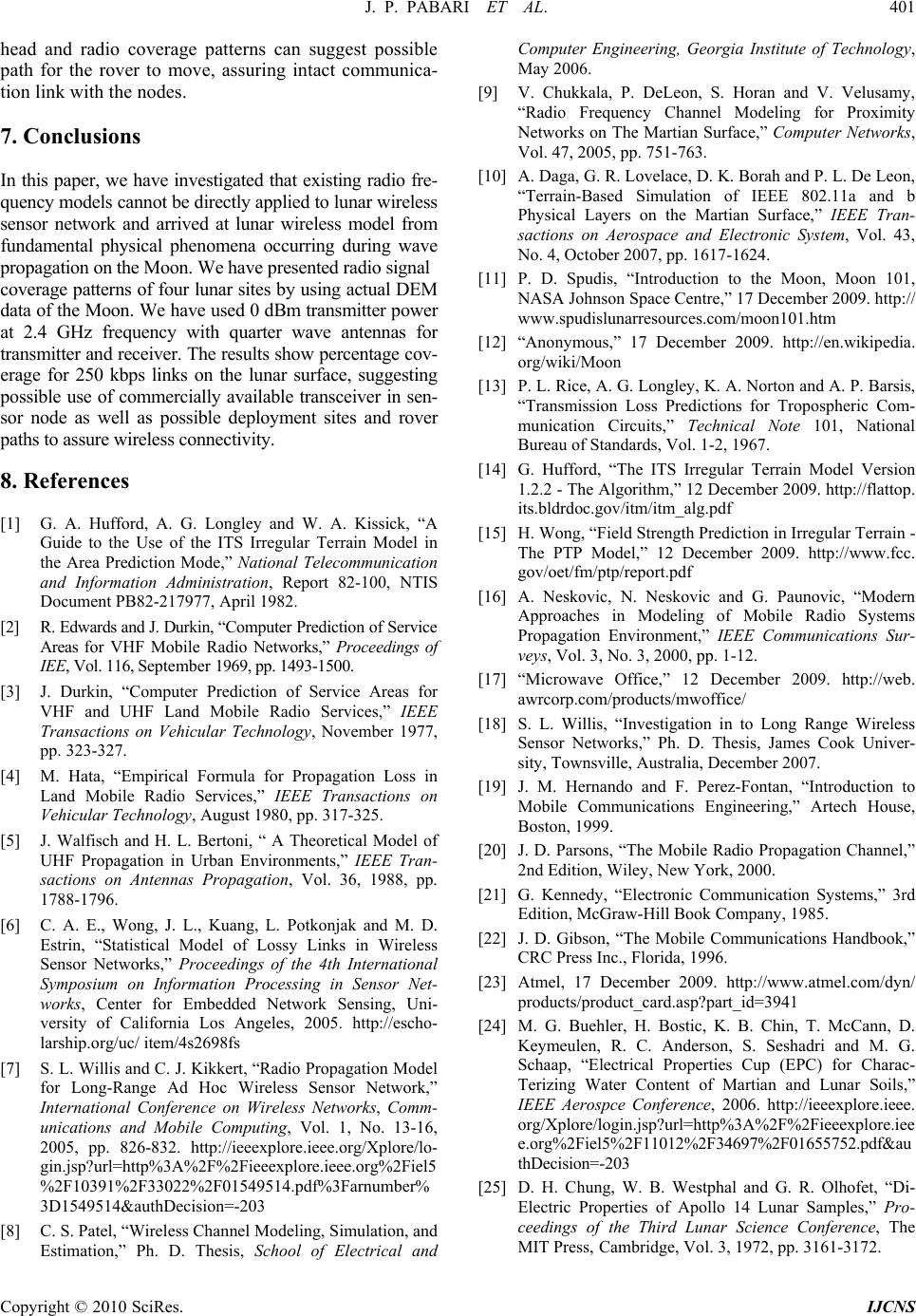 J. P. PABARI ET AL. 401 head and radio coverage patterns can suggest possible path for the rover to move, assuring intact communica- tion link with the nodes. 7. Conclusions In this paper, we have investigated that existing radio fre- quency models cannot be directly applied to lunar wireless sensor network and arrived at lunar wireless model from fundamental physical phenomena occurring during wave propagation on the Moon. We have presented radio signal coverage patterns of four lunar sites by using actual DEM data of the Moon. We have used 0 dBm transmitter power at 2.4 GHz frequency with quarter wave antennas for transmitter and receiver. The results show percentage cov- erage for 250 kbps links on the lunar surface, suggesting possible use of commercially available transceiver in sen- sor node as well as possible deployment sites and rover paths to assure wireless connectivity. 8. References [1] G. A. Hufford, A. G. Longley and W. A. Kissick, “A Guide to the Use of the ITS Irregular Terrain Model in the Area Prediction Mode,” National Telecommunication and Information Administration, Report 82-100, NTIS Document PB82-217977, April 1982. [2] R. Edwards and J. Durkin, “Computer Prediction of Service Areas for VHF Mobile Radio Networks,” Proceedings of IEE, Vol. 116, September 1969, pp. 1493-1500. [3] J. Durkin, “Computer Prediction of Service Areas for VHF and UHF Land Mobile Radio Services,” IEEE Transactions on Vehicular Technology, November 1977, pp. 323-327. [4] M. Hata, “Empirical Formula for Propagation Loss in Land Mobile Radio Services,” IEEE Transactions on Vehicular Technology, August 1980, pp. 317-325. [5] J. Walfisch and H. L. Bertoni, “ A Theoretical Model of UHF Propagation in Urban Environments,” IEEE Tran- sactions on Antennas Propagation, Vol. 36, 1988, pp. 1788-1796. [6] C. A. E., Wong, J. L., Kuang, L. Potkonjak and M. D. Estrin, “Statistical Model of Lossy Links in Wireless Sensor Networks,” Proceedings of the 4th International Symposium on Information Processing in Sensor Net- works, Center for Embedded Network Sensing, Uni- versity of California Los Angeles, 2005. http://escho- larship.org/uc/ item/4s2698fs [7] S. L. Willis and C. J. Kikkert, “Radio Propagation Model for Long-Range Ad Hoc Wireless Sensor Network,” International Conference on Wireless Networks, Comm- unications and Mobile Computing, Vol. 1, No. 13-16, 2005, pp. 826-832. http://ieeexplore.ieee.org/Xplore/lo- gin.jsp?url=http%3A%2F%2Fieeexplore.ieee.org%2Fiel5 %2F10391%2F33022%2F01549514.pdf%3Farnumber% 3D1549514&authDecision=-203 [8] C. S. Patel, “Wireless Channel Modeling, Simulation, and Estimation,” Ph. D. Thesis, School of Electrical and Computer Engineering, Georgia Institute of Technology, May 2006. [9] V. Chukkala, P. DeLeon, S. Horan and V. Velusamy, “Radio Frequency Channel Modeling for Proximity Networks on The Martian Surface,” Computer Networks, Vol. 47, 2005, pp. 751-763. [10] A. Daga, G. R. Lovelace, D. K. Borah and P. L. De Leon, “Terrain-Based Simulation of IEEE 802.11a and b Physical Layers on the Martian Surface,” IEEE Tran- sactions on Aerospace and Electronic System, Vol. 43, No. 4, October 2007, pp. 1617-1624. [11] P. D. Spudis, “Introduction to the Moon, Moon 101, NASA Johnson Space Centre,” 17 December 2009. http:// www.spudislunarresources.com/moon101.htm [12] “Anonymous,” 17 December 2009. http://en.wikipedia. org/wiki/Moon [13] P. L. Rice, A. G. Longley, K. A. Norton and A. P. Barsis, “Transmission Loss Predictions for Tropospheric Com- munication Circuits,” Technical Note 101, National Bureau of Standards, Vol. 1-2, 1967. [14] G. Hufford, “The ITS Irregular Terrain Model Version 1.2.2 - The Algorithm,” 12 December 2009. http://flattop. its.bldrdoc.gov/itm/itm_alg.pdf [15] H. Wong, “Field Strength Prediction in Irregular Terrain - The PTP Model,” 12 December 2009. http://www.fcc. gov/oet/fm/ptp/report.pdf [16] A. Neskovic, N. Neskovic and G. Paunovic, “Modern Approaches in Modeling of Mobile Radio Systems Propagation Environment,” IEEE Communications Sur- veys, Vol. 3, No. 3, 2000, pp. 1-12. [17] “Microwave Office,” 12 December 2009. http://web. awrcorp.com/products/mwoffice/ [18] S. L. Willis, “Investigation in to Long Range Wireless Sensor Networks,” Ph. D. Thesis, James Cook Univer- sity, Townsville, Australia, December 2007. [19] J. M. Hernando and F. Perez-Fontan, “Introduction to Mobile Communications Engineering,” Artech House, Boston, 1999. [20] J. D. Parsons, “The Mobile Radio Propagation Channel,” 2nd Edition, Wiley, New York, 2000. [21] G. Kennedy, “Electronic Communication Systems,” 3rd Edition, McGraw-Hill Book Company, 1985. [22] J. D. Gibson, “The Mobile Communications Handbook,” CRC Press Inc., Florida, 1996. [23] Atmel, 17 December 2009. http://www.atmel.com/dyn/ products/product_card.asp?part_id=3941 [24] M. G. Buehler, H. Bostic, K. B. Chin, T. McCann, D. Keymeulen, R. C. Anderson, S. Seshadri and M. G. Schaap, “Electrical Properties Cup (EPC) for Charac- Terizing Water Content of Martian and Lunar Soils,” IEEE Aerospce Conference, 2006. http://ieeexplore.ieee. org/Xplore/login.jsp?url=http%3A%2F%2Fieeexplore.iee e. org%2 Fie l5%2F11012 %2 F34 69 7%2 F01 655 752.pdf&au thDecision=-203 [25] D. H. Chung, W. B. Westphal and G. R. Olhofet, “Di- Electric Properties of Apollo 14 Lunar Samples,” Pro- ceedings of the Third Lunar Science Conference, The MIT Press, Cambridge, Vol. 3, 1972, pp. 3161-3172. Copyright © 2010 SciRes. IJCNS |