Paper Menu >>
Journal Menu >>
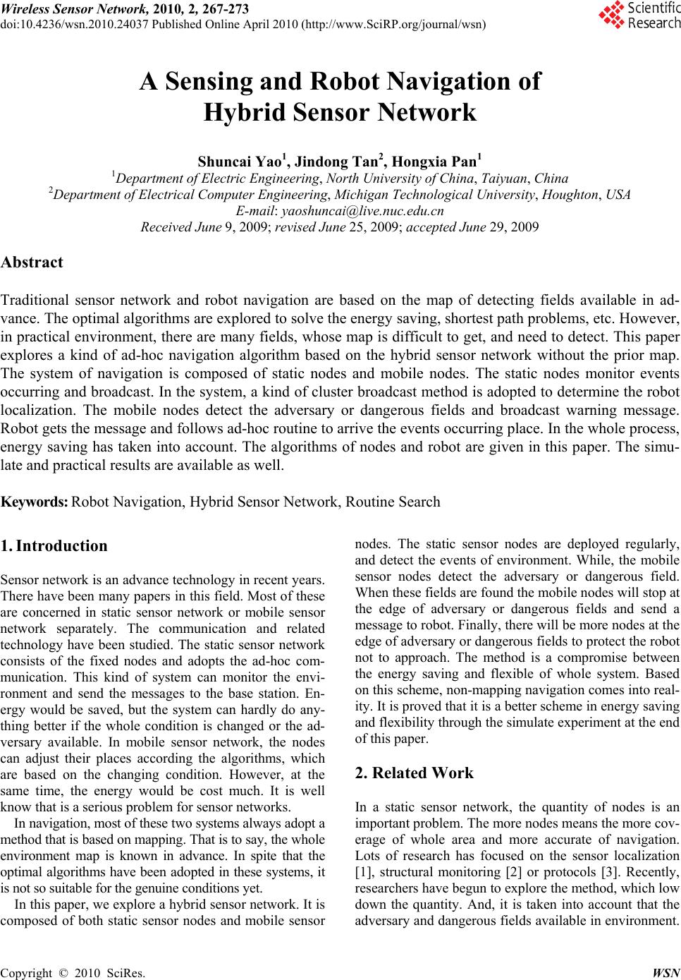 Wireless Sensor Network, 2010, 2, 267-273 doi:10.4236/wsn.2010.24037 Published Online April 2010 (http://www.SciRP.org/journal/wsn) Copyright © 2010 SciRes. WSN A Sensing and Robot Navigation of Hybrid Sensor Network Shuncai Yao1, Jindong Tan2, Hongxia Pan1 1Department of Electric Engineering, North University of China, Taiyuan, China 2Department of Electrical Computer Engineering, Michigan Technological University, Houghton, USA E-mail: yaoshuncai@live.nuc.edu.cn Received June 9, 2009; revised June 25, 2009; accepted June 29, 2009 Abstract Traditional sensor network and robot navigation are based on the map of detecting fields available in ad- vance. The optimal algorithms are explored to solve the energy saving, shortest path problems, etc. However, in practical environment, there are many fields, whose map is difficult to get, and need to detect. This paper explores a kind of ad-hoc navigation algorithm based on the hybrid sensor network without the prior map. The system of navigation is composed of static nodes and mobile nodes. The static nodes monitor events occurring and broadcast. In the system, a kind of cluster broadcast method is adopted to determine the robot localization. The mobile nodes detect the adversary or dangerous fields and broadcast warning message. Robot gets the message and follows ad-hoc routine to arrive the events occurring place. In the whole process, energy saving has taken into account. The algorithms of nodes and robot are given in this paper. The simu- late and practical results are available as well. Keywords: Robot Navigation, Hybrid Sensor Network, Routine Search 1. Introduction Sensor network is an advance technology in recent years. There have been many papers in this field. Most of these are concerned in static sensor network or mobile sensor network separately. The communication and related technology have been studied. The static sensor network consists of the fixed nodes and adopts the ad-hoc com- munication. This kind of system can monitor the envi- ronment and send the messages to the base station. En- ergy would be saved, but the system can hardly do any- thing better if the whole condition is changed or the ad- versary available. In mobile sensor network, the nodes can adjust their places according the algorithms, which are based on the changing condition. However, at the same time, the energy would be cost much. It is well know that is a serious problem for sensor networks. In navigation, most of these two systems always adopt a method that is based on mapping. That is to say, the whole environment map is known in advance. In spite that the optimal algorithms have been adopted in these systems, it is not so suitable for the genuine conditions yet. In this paper, we explore a hybrid sensor network. It is composed of both static sensor nodes and mobile sensor nodes. The static sensor nodes are deployed regularly, and detect the events of environment. While, the mobile sensor nodes detect the adversary or dangerous field. When these fields are found the mobile nodes will stop at the edge of adversary or dangerous fields and send a message to robot. Finally, there will be more nodes at the edge of adversary or dangerous fields to protect the robot not to approach. The method is a compromise between the energy saving and flexible of whole system. Based on this scheme, non-mapping navigation comes into real- ity. It is proved that it is a better scheme in energy saving and flexibility through the simulate experiment at the end of this paper. 2. Related Work In a static sensor network, the quantity of nodes is an important problem. The more nodes means the more cov- erage of whole area and more accurate of navigation. Lots of research has focused on the sensor localization [1], structural monitoring [2] or protocols [3]. Recently, researchers have begun to explore the method, which low down the quantity. And, it is taken into account that the adversary and dangerous fields available in environment. 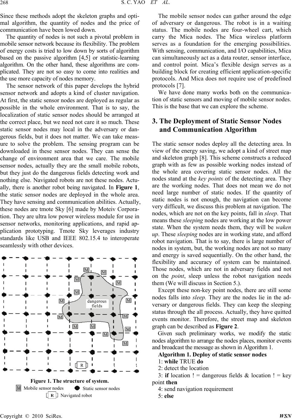 S. C. YAO ET AL. 268 Since these methods adopt the skeleton graphs and opti- mal algorithm, the quantity of nodes and the price of communication have been lowed down. The quantity of nodes is not such a pivotal problem in mobile sensor network because its flexibility. The problem of energy costs is tried to low down by sorts of algorithm based on the passive algorithm [4,5] or statistic-learning algorithm. On the other hand, these algorithms are com- plicated. They are not so easy to come into realities and the use more capacity of nodes memory. The sensor network of this paper develops the hybrid sensor network and adopts a kind of cluster navigation. At first, the static sensor nodes are deployed as regular as possible in the whole environment. That is to say, the localization of static sensor nodes should be arranged at the correct place, but we need not care it so much. These static sensor nodes may local in the adversary or dan- gerous fields, but it does not matter. We can take meas- ure to solve the problem. The sensing program can be downloaded in these sensor nodes. They can sense the change of environment area that we care. The mobile sensor nodes, actually they are the small mobile robots, but they just do the dangerous fields detecting work and nothing else. Navigated robots are not these nodes. Actu- ally, there is another robot being navigated. In Figure 1, the static sensor nodes are deployed in the whole area. They have sensing and communication abilities. Actually, these nodes are tmote Sky [6] made by Moteiv Corpora- tion. They are ultra low power wireless module for use in sensor networks, monitoring applications, and rapid ap- plication prototyping. Tmote Sky leverages industry standards like USB and IEEE 802.15.4 to interoperate seamlessly with other devices. Figure 1. The structure of system. The mobile sensor nodes can gather around the edge of adversary or dangerous. The robot is in a waiting status. The mobile nodes are four-wheel cart, which carry the Mica nodes. The Mica wireless platform serves as a foundation for the emerging possibilities. With sensing, communication, and I/O capabilities, Mica can simultaneously act as a data router, sensor interface, and control point. Mica’s flexible design serves as a building block for creating efficient application-specific protocols. And Mica does not require use of predefined protocols [7]. We have done many works both on the communica- tion of static sensors and moving of mobile sensor nodes. This is the base that we can explore the scheme. 3. The Deployment of Static Sensor Nodes and Communication Algorithm The static sensor nodes deploy all the detecting area. In view of the energy saving, we adopt a kind of street map and skeleton graph [8]. This scheme constructs a reduced graph with as few as possible working nodes instead of the whole area covering static sensor nodes. All the nodes stand at the key points of the detecting area. They are the working nodes. That does not mean we do not need large number of static nodes. If the quantity of static nodes is not enough, the navigation can become very difficult, we discuss this problem at navigation. The nodes, which are not on the key points, fall in sleep. That means these sleeping nodes are working at the low power state. When the system needs them, they will be waken up. These sleeping nodes are in working state, and afford robot navigation. That is to say, there is large number of nodes in system, but, the working nodes are not so many and energy is saved sequentially. On the other hand, the flexibility and accuracy of system can be maintained. Those nodes, which are not in adversary fields and not on the point, sleep unless the robot navigation needs them (We will discuss in Section 5.). Except these non-key point nodes, there are still some nodes falls into sleep. They are the nodes lie in the ad- versary or dangerous fields. They can keep the sleeping status through the all process. Actually, they have quitted events monitor. Therefore, the street map and skeleton graph can be described as Figure 2. Given such preliminary works, we modify the static nodes algorithm to arrange the nodes places, monitor events and broadcast the message as shown in Algorithm 1. Algorithm 1. Deploy of static sensor nodes 1: while TRUE do 2: detect the location 3: if location ! = dangerous fields & location ! = key point then 4: send navigation requirement 5: else Mobile sensor nodes Static sensor nodes N avigated robo t Copyright © 2010 SciRes. WSN 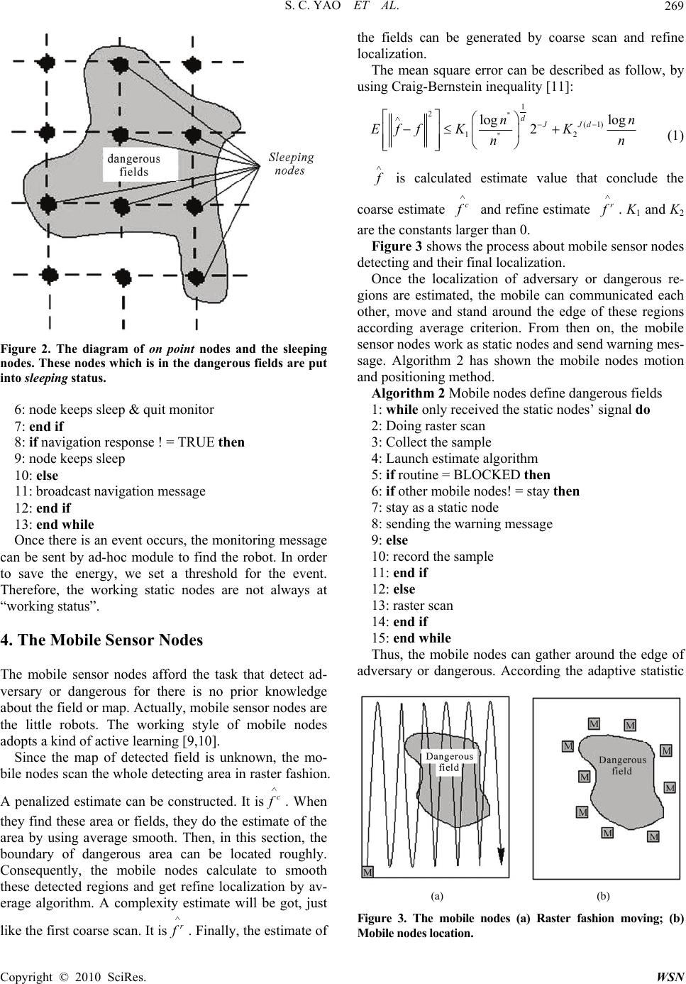 S. C. YAO ET AL.269 Figure 2. The diagram of on point nodes and the sleeping nodes. These nodes which is in the dangerous fields are put into sleeping status. 6: node keeps sleep & quit monitor 7: end if 8: if navigation response ! = TRUE then 9: node keeps sleep 10: else 11: broadcast navigation message 12: end if 13: end while Once there is an event occurs, the monitoring message can be sent by ad-hoc module to find the robot. In order to save the energy, we set a threshold for the event. Therefore, the working static nodes are not always at “working status”. 4. The Mobile Sensor Nodes The mobile sensor nodes afford the task that detect ad- versary or dangerous for there is no prior knowledge about the field or map. Actually, mobile sensor nodes are the little robots. The working style of mobile nodes adopts a kind of active learning [9,10]. Since the map of detected field is unknown, the mo- bile nodes scan the whole detecting area in raster fashion. A penalized estimate can be constructed. It isc f . When they find these area or fields, they do the estimate of the area by using average smooth. Then, in this section, the boundary of dangerous area can be located roughly. Consequently, the mobile nodes calculate to smooth these detected regions and get refine localization by av- erage algorithm. A complexity estimate will be got, just like the first coarse scan. It isr f . Finally, the estimate of the fields can be generated by coarse scan and refine localization. The mean square error can be described as follow, by using Craig-Bernstein inequality [11]: 1 2'' (1) 12 '' log log 2 dJJd nn Eff KKn n (1) f is calculated estimate value that conclude the coarse estimate c f and refine estimate r f . K1 and K2 are the constants larger than 0. Figure 3 shows the process about mobile sensor nodes detecting and their final localization. Once the localization of adversary or dangerous re- gions are estimated, the mobile can communicated each other, move and stand around the edge of these regions according average criterion. From then on, the mobile sensor nodes work as static nodes and send warning mes- sage. Algorithm 2 has shown the mobile nodes motion and positioning method. Algorithm 2 Mobile nodes define dangerous fields 1: while only received the static nodes’ signal do 2: Doing raster scan 3: Collect the sample 4: Launch estimate algorithm 5: if routine = BLOCKED then 6: if other mobile nodes! = stay then 7: stay as a static node 8: sending the warning message 9: else 10: record the sample 11: end if 12: else 13: raster scan 14: end if 15: end while Thus, the mobile nodes can gather around the edge of adversary or dangerous. According the adaptive statistic (a) (b) Figure 3. The mobile nodes (a) Raster fashion moving; (b) Mobile nodes location. Copyright © 2010 SciRes. WSN 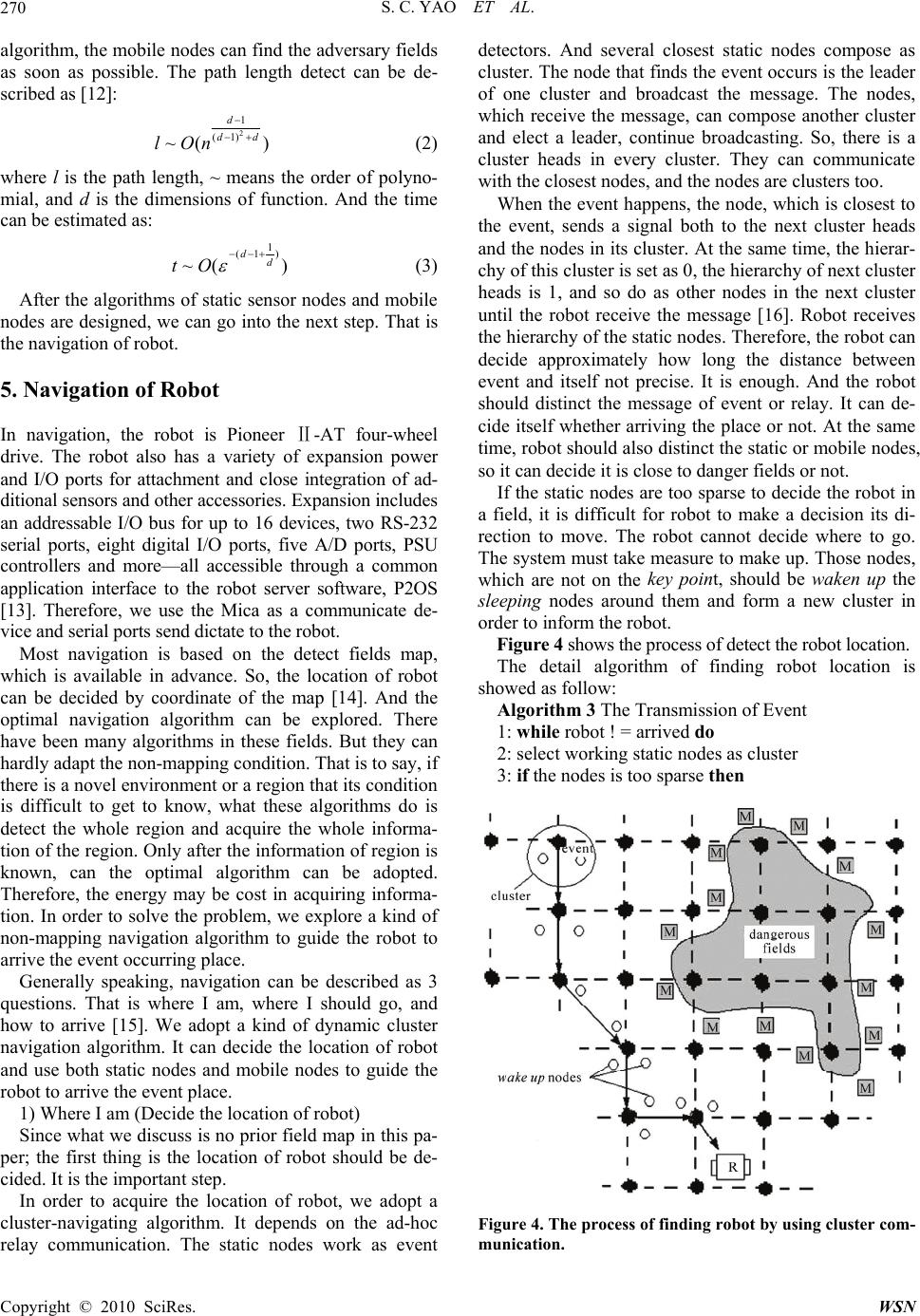 S. C. YAO ET AL. 270 algorithm, the mobile nodes can find the adversary fields as soon as possible. The path length detect can be de- scribed as [12]: 2 1 (1) ~( ) d dd lOn (2) where l is the path length, ~ means the order of polyno- mial, and d is the dimensions of function. And the time can be estimated as: 1 (1 ) ~( ) dd tO (3) After the algorithms of static sensor nodes and mobile nodes are designed, we can go into the next step. That is the navigation of robot. 5. Navigation of Robot In navigation, the robot is Pioneer Ⅱ-AT four-wheel drive. The robot also has a variety of expansion power and I/O ports for attachment and close integration of ad- ditional sensors and other accessories. Expansion includes an addressable I/O bus for up to 16 devices, two RS-232 serial ports, eight digital I/O ports, five A/D ports, PSU controllers and more—all accessible through a common application interface to the robot server software, P2OS [13]. Therefore, we use the Mica as a communicate de- vice and serial ports send dictate to the robot. Most navigation is based on the detect fields map, which is available in advance. So, the location of robot can be decided by coordinate of the map [14]. And the optimal navigation algorithm can be explored. There have been many algorithms in these fields. But they can hardly adapt the non-mapping condition. That is to say, if there is a novel environment or a region that its condition is difficult to get to know, what these algorithms do is detect the whole region and acquire the whole informa- tion of the region. Only after the information of region is known, can the optimal algorithm can be adopted. Therefore, the energy may be cost in acquiring informa- tion. In order to solve the problem, we explore a kind of non-mapping navigation algorithm to guide the robot to arrive the event occurring place. Generally speaking, navigation can be described as 3 questions. That is where I am, where I should go, and how to arrive [15]. We adopt a kind of dynamic cluster navigation algorithm. It can decide the location of robot and use both static nodes and mobile nodes to guide the robot to arrive the event place. 1) Where I am (Decide the location of robot) Since what we discuss is no prior field map in this pa- per; the first thing is the location of robot should be de- cided. It is the important step. In order to acquire the location of robot, we adopt a cluster-navigating algorithm. It depends on the ad-hoc relay communication. The static nodes work as event detectors. And several closest static nodes compose as cluster. The node that finds the event occurs is the leader of one cluster and broadcast the message. The nodes, which receive the message, can compose another cluster and elect a leader, continue broadcasting. So, there is a cluster heads in every cluster. They can communicate with the closest nodes, and the nodes are clusters too. When the event happens, the node, which is closest to the event, sends a signal both to the next cluster heads and the nodes in its cluster. At the same time, the hierar- chy of this cluster is set as 0, the hierarchy of next cluster heads is 1, and so do as other nodes in the next cluster until the robot receive the message [16]. Robot receives the hierarchy of the static nodes. Therefore, the robot can decide approximately how long the distance between event and itself not precise. It is enough. And the robot should distinct the message of event or relay. It can de- cide itself whether arriving the place or not. At the same time, robot should also distinct the static or mobile nodes, so it can decide it is close to danger fields or not. If the static nodes are too sparse to decide the robot in a field, it is difficult for robot to make a decision its di- rection to move. The robot cannot decide where to go. The system must take measure to make up. Those nodes, which are not on the key point, should be waken up the sleeping nodes around them and form a new cluster in order to inform the robot. Figure 4 shows the process of detect the robot location. The detail algorithm of finding robot location is showed as follow: Algorithm 3 The Transmission of Event 1: while robot ! = arrived do 2: select working static nodes as cluster 3: if the nodes is too sparse then Figure 4. The process of finding robot by using cluster com- munication. Copyright © 2010 SciRes. WSN  S. C. YAO ET AL.271 4: wake up the sleeping nodes 5: else 6: static nodes work as cluster 7: end if 8: if event = TRUE then 9: hierarchy = 0 10: broadcast message 11: else 12: if received message = TURE then 13: hierarchy < - hierarchy+1 14: broadcast 15: end if 16: end if 17: end while 2) Where should I go In a large scope, robot can move to the direction whose hierarchy is always lowing. When robot arrives in the range of cluster, the static nodes should shut down the message broadcasting and its hierarchy minus one. While in the cluster, robot always finds the leader of this cluster. 3) How to arrive The robot can follow a routine, which the nodes’ hier- archy is lowing unless it receives the warning message of the mobile nodes. When it receives warning message of the mobile nodes, it have to use the smooth routine in order to pass the danger field until the warning message vanish. Finally, the robot will arrive the place where events occur when it receive the event’s source message. The distance from robot to dangerous fields can be calculated by potential [17]: 1 22 2 11 (, ),0 () xy R xy > (4) where R is the Euclidean distance from the edge to the mobile nods. In this paper, it can be shown as: 2 ()( iieie 2 ) x xyy (5) (xe, ye) is the location of dangerous fields. The energy of mobile nodes can be defined as follow: 2 1 11 () 22 m iiiv i Vk kv 2 i (6) Therefore, we can conclude the algorithm of robot navigation. There are still some handicaps (they are the points not area) in the robot routine, but there is sonar in the robot. The robot can avoid these handicap points. It is the algorithm 4 shown as follow: Algorithm 4 Navigation of Robot 1: While event message received = TURE Do 2: if arrived ! = TURE then 3: if mobile warning message ! = TURE then 4: use sonar (or communicate with the static nodes) follow navigation routine 5: else 6: adopt the smooth routine 7: end if 8: else 9: send arrive message 10: inform the event node turn off requirement 11: end if 12: end while Since there is no map in advance, what the robot does is receive the message and do probing motion. Thus, the time to arrive the event is not shortest and navigation routine is not the optimal routine. It is the cost of none prior map available and the lower cost of both static and mobile nodes. On the other hand, there are no so many working nodes in this system, the energy cost of nodes can be saved. 4) How to wake up the sleeping nodes When the static nodes, which are on the key point, is too sparse to accomplish the navigation task, it is neces- sary to wake up the sleeping nodes. At first, the cluster head, the static nodes on the key point, acquires the message and sends the message to next closed cluster head. If the closed cluster head can receive the message, it will send back a message to the sending cluster head. That means that the statistic nodes are not too sparse there. The message can relay to the next static nodes. If the closed cluster head cannot re- ceive the message, it cannot send back the message to the sending cluster head. It means that the statistic nodes are too sparse there. That is to say, the sleeping nodes in the cluster have to be waken up in order to relay the mes- sage. The construction of the information deliver is shown in Figure 5. The static nodes in this system adopt tmote Sky [6] made by Moteiv Corporation. They are ultra low power wireless module for use in sensor networks, monitoring applications, and rapid application prototyping. In an open Figure 5. The construction of information deliver in a cluster. Copyright © 2010 SciRes. WSN  S. C. YAO ET AL. 272 field, the communication distance of tmote nodes can reach 100 meters. But in this system, the communication distance of tmote nodes is restrained to 10 meters in or- der to saving energy. In a cluster, there is one tmote node working as the cluster and the other nodes working as sleeping nodes. The event occurs, such as the tempera- ture is over the threshold, the cluster head sends the message to the next cluster head. If the next cluster head receives the message, it sends back a message to the former cluster. Consequently, message can be relayed on. If the sending cluster head does not receive the backing message of the next cluster head, the sending cluster head will send a signal to the sleeping nodes in its cluster, in order to wake up these sleeping nodes. That is to say, the low power costs’ nodes (sleeping nodes) will transfer from the low power costs’ state (sleeping) to working state (waken up). Once the sleeping nodes are waken up, they can afford the message delay events. After the works have been accomplished, we simulate the sensing and navigation of hybrid sensor network by using. Figure 6 and Figure 7 is result of simulating ex- periments. It can be seen that the energy saving of mobile work is better than the static network. While, the energy saving of hybrid network is much better than the mono-static and mono-mobile network. The practical experiments are performed with the setup shown in Figure 8. A sequence process of naviga- tion is shown from (a) to (d). An emergent event occurs by a node(the temperature is over the threshold), the ro- bot (Pioneer Ⅱ-AT) should find the node and arrive the place in time. Part (a) shows the initial experiments situation. There are 100 tmote nodes (static nodes) and 8 small robots with the tmote nodes on them(mobile nodes) in a 25m2 (5m×5m) filed. The lawn simulates the dan- gerous fields, and the scope can be detected by moisture Figure 6. The result of simulating and the trajectory of robot. Figure 7. The energy conservation of different network. (a)(b) (c) (d) Figure 8. The practical experiments of the navigation. sensor on tmote nodes. Therefore, the range of dangerous fields can be defined by them. Consequently, part (b) shows the dangerous fields are defined. Part (c) shows the process of navigation, and part (d) shows the robot arrive the emergency place (red circle) finally. Despite the difficulties with the dangerous fields’ definition, the navigation is successfully performed many times. Although arriving the final location of the robot is not so quickly (about 3 minutes), the robot avoids the danger fields and being guided by this hybrid sensor network system indeed. We plan to conduct further re- search to get higher speed of this navigation system. 6. Conclusions This implementation demonstrated robot guidance by a hybrid sensor network. The energy saving in sensor net- work is an important problem. We take it as the primary Copyright © 2010 SciRes. WSN  S. C. YAO ET AL. Copyright © 2010 SciRes. WSN 273 problem in this system. The skeleton of adversary or dangerous fields can be outlined by using the mobile sensor nodes and the robot navigation comes into reali- ties on the ad-hoc method. In spite of the less optimal routine, it is an effective scheme when there is no map of the whole detecting fields in advance. However, the precision of the navigation system greatly depends on the robot hardware. Navigation can be problematic if environmental factors are not so ideal, such as electrical cables, higher power electrical equip- ment and steel structures exist. Although it is possible to compensate for these effects in a known environment, a search situation may not permit elaborate offline calibra- tion. In addition, the response speed of whole system should be raised higher. We are going to do further re- search on them. 7. Acknowledgment We would like to give special thanks to Dr. Jindong Tan, the professor of Michigan Technological University in U.S.A. for his providing of experimental equipment and environment. The same thanks go to Qi An, who helped me with studies of the project and sensor network, TinyOS. 8. References [1] D. Moore, J. Leonard, D. Rus and S. Teller, “Robust Distributed Networklocalization with Noisy Range Meas- urements,” Proceedings of the 2nd International Confer- ence on Embedded networked sensor systems, Baltimore, 2004, pp. 50-61. [2] R. Szewczyk, A. Mainwaring, J. Polastre and D. Culler, “An Analysis of a Large Scale Habitat Monitoring Ap- plication,” Proceedings of the 2nd International Confer- ence on Embedded networked sensor systems, Baltimore, 2004, pp. 214-226. [3] J. Polastre, J. Hill and D. Culler, “Versatile Low Power Media Access for Wireless Sensor Networks,” Proceed- ings of the 2nd International Conference on Embedded networked sensor systems, Baltimore, 2004, pp. 95-107. [4] M. Batalin, M. Rahimi, Y. Yu, D. Liu, A. Kansal, G. Suk- hatme, W. Kaiser, M. Hansen, G. Pottie, M. Srivastava and D. Estrin, “Call and Response: Experiments in Sampling the Environment,” Proceedings of ACM Sensor Systems, Los Angeles, 2004. [5] M. Rahimi, R. Pon, W. J. Kaiser, G. S. Sukhatme, D. Estrin and M. Srivastava, “Adaptive Sampling for Environmental Robotics,” Proceedings of IEEE International Conference on Robotics and Automation, Los Angeles, 2004. [6] http://www.moteiv.com [7] http://www.crossbow.com [8] R. Willett, A. Martin and R. Nowak, “Backcasting: Adaptive Sampling for Sensor Networks,” Proceedings of IEEE International Conference on Information process- ing in sensor networks, New York, 2004, pp. 124-133. [9] R. Castro, R. Willett and R. Nowak, “Faster Rates in Re- gression via Active Learning,” Proceedings of Neural In- formation Processing Systems, 2005. http://homepages.cae. wisc.edu/ rcastro/ ECE-05-3.pdf [10] M. Horstein, “Sequential Decoding Using Noiseless Feed- back,” IEEE Transactions Information Theory, Vol. 9, No. 3, 1963, pp. 136-143. [11] J. Borenstein and H. R. Everett, “Navigating Mobile Ro- bots: Sensors and Techniques,” John Wiley & Sons, 1992. [12] M. Burnashev and K. S. Zigangirov, “An Interval Esti- mation Problem for Controlled Observations,” Problems in Information Transmission, Vol. 10, 1974, pp. 223-231. [13] O. Khatib, “Real-Time Obstacle Avoidance for Manipu- lators and Mobile Robots,” The International Journal of Robotics Research, Vol. 5, No. 1, 1986, pp. 90-98. [14] J. Cortes, S. Martinez, T. Karatas and F. Bullo, “Cover- age Control for Mobile Sensing Networks,” IEEE Trans- actions on Robotics and Automation, New Orleans, April 2004, pp. 243-255. [15] A. Korostelev, “On Minimax Rates of Convergence in Image Models under Sequential Design,” Statistics and Probability Letters, Vol. 43, 1999, pp. 369-375. [16] G. Golubev and B. Levit, “Sequential Recovery of Ana- lytic Periodic Edged in the Binary Image Models,” Mathe- matical Methods of Statistics, Vol. 12, 2003, pp. 95-115. [17] R. Castro, R. Willett and R. Nowak, “Faster Rates in Re- gression via Active Earning,” Proceedings of Neural In- formation Processing Systems, Vancouver, 2005. http:// homepages.cae.wisc.edu/rcastro/ECE-05-3. pdf |