Natural Science
Vol.5 No.5(2013), Article ID:32129,19 pages DOI:10.4236/ns.2013.55081
High power optics and its new manifestations
![]()
Prokhorov General Physics Institute of RAS, Vavilova Str. 38, Moscow, Russia; vapollo@kapella.gpi.ru
Copyright © 2013 Victor V. Apollonov. This is an open access article distributed under the Creative Commons Attribution License, which permits unrestricted use, distribution, and reproduction in any medium, provided the original work is properly cited.
Received 17 January 2013; revised 20 February 2013; accepted 3 March 2013
Keywords: Heat Transfer; Surface Deformation; Optical Polishing; Reflectivity; Intermetallic Coatings; Porous Structures; LD Structures; Silicon Carbide; Space-Based Telescopes
ABSTRACT
The advent of the laser has placed stringent requirements on the fabrication, performance and quality of optical elements employed within systems for most practical applications. Their high power performance is generally governed by three distinct steps, firstly the absorption of incident optical radiation (governed primarily by various absorption mechanisms); secondly, followed by a temperature increase and response governed primarily by thermal properties and finally the elements thermo-optical and thermomechanical response, e.g., distortion, stress birefringenous fracture, etc. All of which needs to be understood in the design as efficient, compact, reliable and useful for many applications high power systems, under a variety of operating conditions, pulsed and continuous wave, rep-rated or burst mode of varying duty cycles.
1. INTRODUCTION
Archaeologists claim that people learned to make mirrors more than five thousand years ago. At home they used polished bronze or silver plates, and only ancient Romans started to manufacture glass mirrors with a tin or lead coating. The technology of mirror production changed many times, but basically all the mirrors were either metal-coated glass or quartz. Never before, the energy of radiation fluxes was so damaging to mirrors because they reflected very little light, for example, from distant stars, from a candle flame or splinter.
Modern problems of interaction of optical mirrors with high-power radiation arose with the advent of first lasers. Virtually in all types of lasers generation occurs in a resonator, which consists of at least a pair of mirrors, and through one of them radiation is emitted. Initially, traditional quartz disks with a mirrored surface suited well the purpose, but over the years passed, the power of laser radiation fluxes has increased thousand fold. Today, the problem of making a mirror that can operate and maintain its high optical performance when exposed to intense radiation has become one of the key challenges in the improvement of high-power lasers and modern high-energy systems. Design, materials testing and technological ideas are used in power optics work and are extremely useful for specialists involved in the development of astronomical and space optics, new efficient systems based on laser diode assemblies, and in many other areas of the ever-expanding knowledge.
2. OPTICS OF HIGH-POWER LASERS
Back in the early 1970s, we drew attention to the phenomenon, which, of course, was to limit the further growth of the power generated by the laser system and, consequently, the intensity of the laser beam on the surface of the irradiated object [1-14]. More than twenty years of fundamental and applied research devoted to the study of this phenomenon and to the solution of problems associated with it allow a conclusion that its essence consists in the following.
The optical surface of even a very good mirror does not fully reflect radiation falling on it. A small portion of energy (fractions of a percent, depending on the wavelength) is absorbed by the mirror and turns into heat. As the laser beam power increases, even a small amount of it is sufficient to induce thermal stresses in a mirror. They distort the geometry of the reflecting surface, which influence, for example, such an important property of laser light, as the possibility of its propagation over long distances and concentration in a small volume. Now we know that thermal deformation of mirrors not only affect the main characteristics of the beam, but also lead to quenching of generation. And is it possible to manufacture a mirror, which can resist a flux of radiation power of a few megawatts? This question was probably the main one in the world laser community of the early 1970s. The General Physics Institute and enterprises of the defense complexes working under its leadership are carrying out research in the field of so-called high-intensity laser optics or power optics. The main requirement to power optics is a high threshold of optical performance. For each type of a laser system, depending on its applications the permissible value of the elastic distortion of the mirror surface is specified, which, for example, is measured in fractions of a percent of a laser wavelength of a specific laser system. For a CO2 laser the generated radiation lies in the infrared region of the spectrum, and the wavelength is 10.6 µm; therefore, the elastic distortion shall not exceed fractions of a micron. Even higher requirements are imposed on the optics of the short-wavelength range. The light intensity, at which the distortions of the mirror surface reach some limits for a specified laser source, is an optical performance threshold of the mirror. It means that the better the optical quality of the mirror material, the higher the threshold of optical performance at higher intensities. This threshold level cannot be violated, because elastic deformations of the mirror change the shape of the laser beam, which will ultimately affect the prospects of delivering the light energy to the interaction region. If the light load is further increased, then deformations become inelastic (plastic), which means that irreversible changes are produced on the mirror, i.e., its reflecting surface is damaged and should be replaced. Therefore, it is needed to manufacture mirrors, which could withstand high optical loads for quite a long time, i.e., up to several kilowatts per square centimeter of the mirror surface.
To understand how difficult this task is, it is enough to give two examples. The mirror, which has been in the hands of an experimenter for only a few seconds, can exhibit deformations of the optical surface that is close to the maximum permissible value, because of the uneven hand heating. However, in this case, if the mirror is left to cool, the shape will be restored. In reality mirrors of modern high-power lasers are exposed to power densities of several kilowatts per square centimeter, which is comparable to the energy flux, which is emitted into the environment directly from the unit surface of the Sun. And this means that if we somehow contrived to “put a laser mirror on the Sun”, the shape of its surface should not change significantly even in this case.
To solve this problem and manufacture highly resistant mirrors necessary for high-power industrial lasers, it was necessary to unravel a tangle of issues related to quantum electronics, optics, thermal elasticity and heat transfer, materials science, and many other modern technologies.
It would seem that the first step on this path is obvious: to replace a semitransparent quartz disk on a metal one and couple light out by diffraction through an aperture in the mirror or over its boundary. Metals perfectly reflect laser light, have high thermal conductivity and, therefore, may well remove heat from the region of interaction of the beam with the mirror surface. But pure metals also have disadvantages: (a) high thermal expansion coefficient—they can easily change their size and shape when heated, and (b) relatively low hardness, because of which it is difficult to polish them as well as quartz.
Here it is necessary to say that the modern advances in optical polishing of metals are largely connected with the search for the solution to the problems of laser mirrors. It is funny now to recall an old episode, when physicists first came to opticians with a piece of metal. The request to polish a metal disc in the same room with quartz or calcite was simply wild because metal dust in the workshop, where ultra-precision machining of optical surfaces is performed, was inaccessible. Yet, the way out of this situation was found, i.e., a metallic mirror. And, in fact, after examining all available metals and alloys, scientists managed to increase the optical performance threshold of new mirrors over traditional quartz mirrors by an order of magnitude. But this “order of magnitude” was not enough. It became clear that the required level of light, and thus of heat loads on the mirror of a high-power laser can be achieved only by using special cooling.
3. COOLING OF MIRRORS
When cooled with a moving liquid, the heat flow being released is directly proportional to the temperature difference between a hot body and coolant. Thermal power rates measuring kilowatts per square centimeter are not difficult to remove, if the mirror is heated to a temperature of thousands of degrees. But in this case, it is impossible to talk about the high optical quality of the mirror surface. There is a contradiction: convective heat exchange is greater at high temperatures, and for the geometric shape and other characteristics of the optical mirrors to be stable, room temperatures are needed. This contradiction could only be resolved due to more efficient heat removal; however, for room temperatures of optical surfaces of a laser mirror, neither the theory nor the practice was developed at that time.
First, scientists started experimenting with milling deep channels on the back side of a metal disk through which tap water was circulating. They were cut as close to the surface as possible, but this lead to vibration and deformation of the mirror surface due to pressure fluctuations of water. Then, there was an attempt to make the channels shallower and manufacture micro-capillary structures [15-27]. This approach led to the conclusion that it is better to use specially designed metal capillary-porous structures, similar to a sponge for washing dishes. As a result, so-called felt and powder metal-based structures have been widely adopted. Heat exchange in these structures is very intense, both due to the large surface, and due to the strong mixing of the coolant, which travels in the micro-capillaries. In addition, the matrix with a porous body skeleton functions as a supporting structure: each of its elements is linked with the mirror surface and keeps its original geometry. The coolant in such a structure behaves as a turbulent mountain stream that runs through branched and sinuous gorges. And the matrix of the porous body in this case resembles an openwork design of the bridge with a smooth road surface supported by many piers.
4. MIRROR SURFACE
A thin but very hard layer, which is then polished, must be applied to a highly porous heat exchanger. Only then its surface will serve as a mirror provided that it has a highly reflective coating. The thickness of the coating separating radiation from the coolant should be small, i.e., 100 - 300 µm; otherwise, it will keep the heat absorbed by the reflecting surface of the mirror. Now there are several methods of applying thin layers on a highly porous material, but initially it was quite a challenging task. The problem was solved by using intermetallic compounds [17-19], i.e., chemical compounds of metals with each other. Intermetallic coatings are obtained, for example, by deposition from the gas phase. So it is possible not only produce a thin separating layer, but also to restore the mirror if necessary.
Intermetallic coatings have another important property: their structure allows one to manufacture mirror surfaces of high optical quality. If one looks on a polished metal through a microscope, its surface resembles an orange peel: it is covered with tiny hillocks and cavities. To reduce the micro-roughness additional measures are needed, for example, before polishing the metal is doped to make it harder and more fine-grained. But all the same the final size of micro-roughness is too large: from 0.01 to 0.1 µm. In intermetallic coatings the structure is originally very small, about 0.1 µm, and after treatment with a diamond cutter or optical polishing very good mirror surfaces with roughness less than a few thousandths of a micron can be manufactured.
Thus, the solution was found. A mirror for high-power CW and pulse-periodic lasers, where the average output power levels are high or very high, is a highly porous heat exchanger and a thin separation layer with a reflective coating. Lasers with such mirrors have been successfully used for welding, cutting and hardening of metals in industry. Besides, they are employed for addressing environmental problems and in military applications.
But it turned out that there is still room for improvement in high power optics. By changing the coolant pressure, one can make it boil at room temperature [21-35], i.e., in the same conditions under which the final optical machining of the mirror surface is carried out. When the coolant boils, a portion of the absorbed heat is spent on vapor formation; therefore, the heat exchange is tens or hundreds of times higher than in the case of the convective heat exchange. It is only need to remove bubbles from the capillary-porous structure, i.e., the size of the capillaries should be selected accordingly. And then water can be replaced with a liquid metal, for example, the eutectic alloys of sodium, potassium and cesium, which have a low melting point. The heat exchange rate becomes even higher: the heat is now not only removed by the moving fluid, but also is transferred to the coolant itself, which, like all metals, is an excellent heat conductor. Liquid metal coolants enable the removal of thermal powers from a reflecting surface, measuring ten kilowatts per square centimeter of surface.
Using the methods of metallic mirror cooling, one can solve such “non-mirror” problem as the cooling of large integrated circuits and the development of high-power anodes of X-ray lithography facilities for microelectronics. These devices must withstand the heat load measuring a few tens or hundreds of kilowatts per square centimeter. Works on creation of high-power optics for highpower lasers involve introduction of a wide range of technical, technological and design solutions from other areas of science [28,32].
5. MIRRORS BASED ON MONOLITE MATERIALS
5.1. Temperature Field of Mirrors
Consider a strongly absorbing elastically isotropic body, which at the initial moment of time is kept at zero temperature in a relaxed state and on whose surface an axisymmetric radiative flux is incident [1-14]. The energy distribution in the laser beam cross section obeys the Gaussian 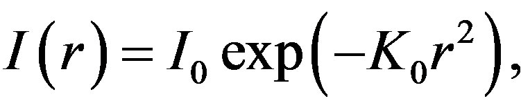 where
where  and
and  is the radius of the irradiation region on the body surface. We assume that all the thermal and mechanical coefficients of the material do not depend on temperature, and the laser beam is absorbed directly on the irradiated surface. The nonlinear effects, as well as the energy loss by radiation and convection are neglected. Provided that the characteristic size of the beam is
  and the time of energy input is
  (L is the characteristic size of the body, and a is the thermal conductivity of the material), the problem can be solved by using the half-space model (Figure 1).
In this formulation, the problem of determining the temperature field is reduced to the solution of the differential equation of heat conduction for the following
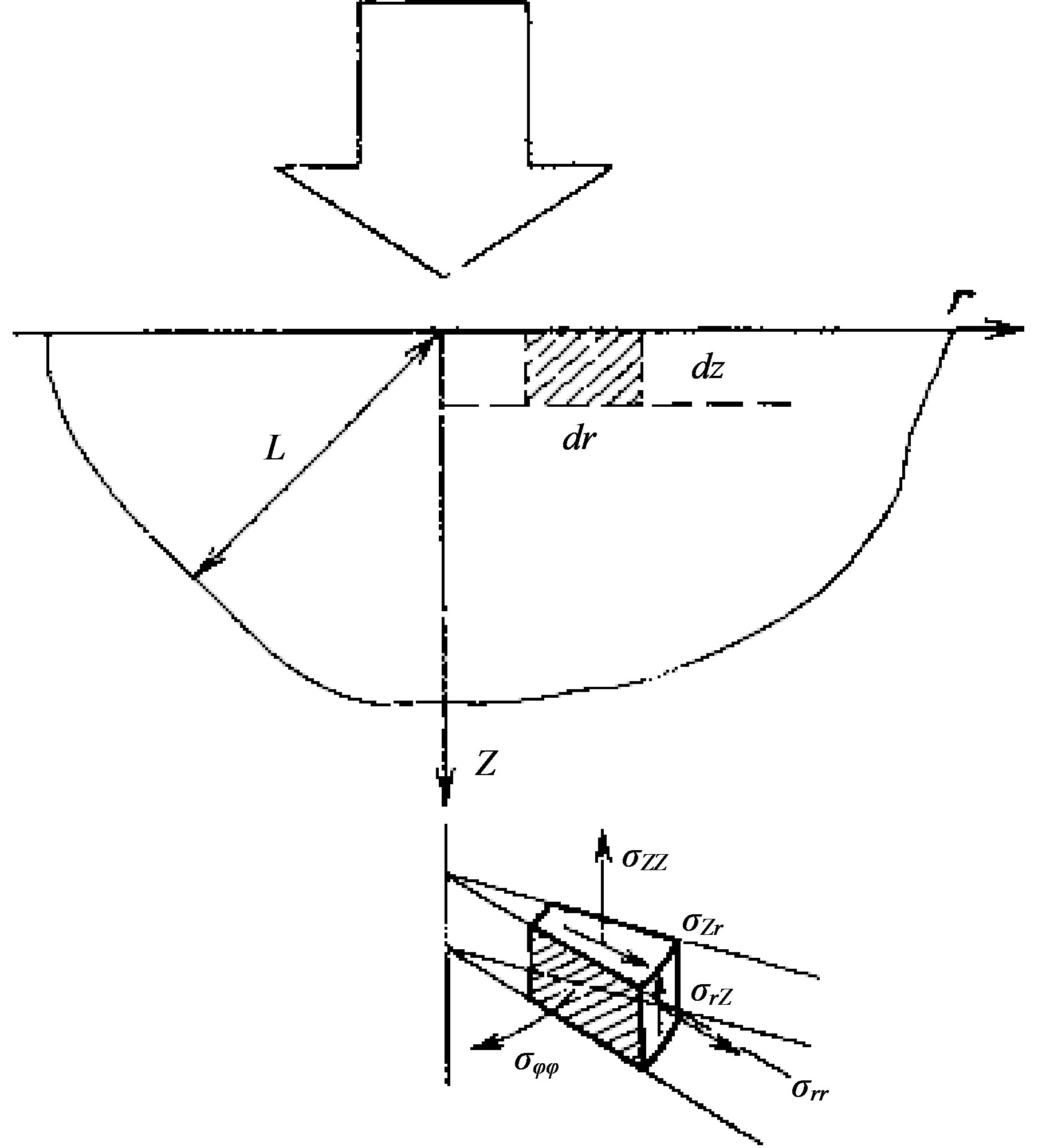
Figure 1. CO2-laser radiation on the surface of solid body.
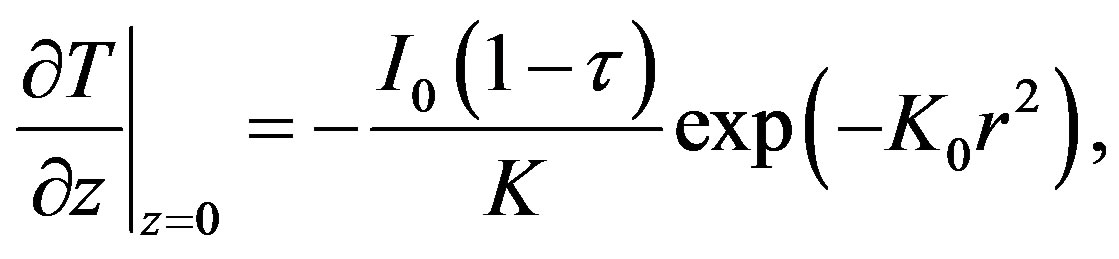
initial and boundary conditions:
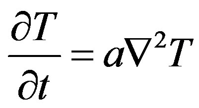 (1)
(1)
 (2)
(2)
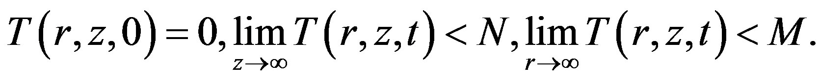 (3)
(3)
Here, K is the thermal conductivity and  is the reflectivity of the material surface.
By applying to (1) the Hankel transform over r and the Laplace transform over t and using the initial and boundary conditions (3), we obtain:
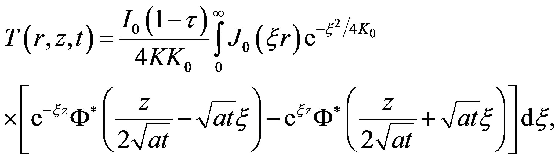 (4)
(4)
where  is the zero-order Bessel function and
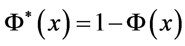 ;
;  is the error function.
The behavior of the temperature field on the surface of the body exposed to a laser beam is shown by the example of a quartz sample with a gold coating . Figure 2 shows the surface temperature profiles calculated for several time points.
However, if the exposure time satisfies the inequality  then a stationary temperature field can establish. In this case, the expression for the temperature has the form:
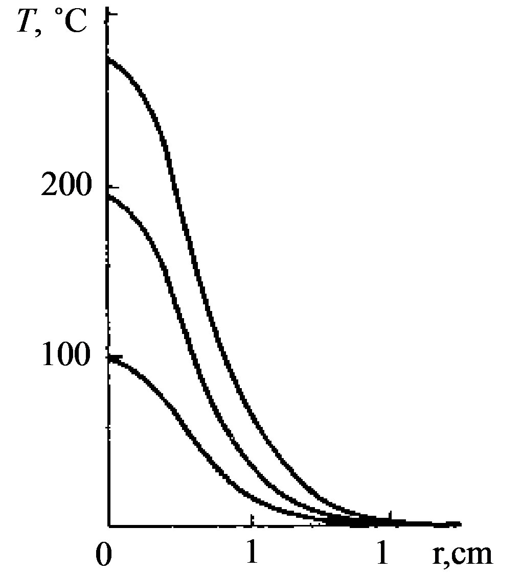
Figure 2. Temperature profile dependence in time on the solid surface covered by gold.
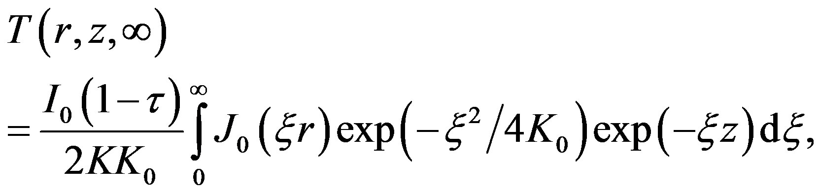 (5)
(5)
at the point  where the maximum temperature is reached. Then, expression (5) is simplified:
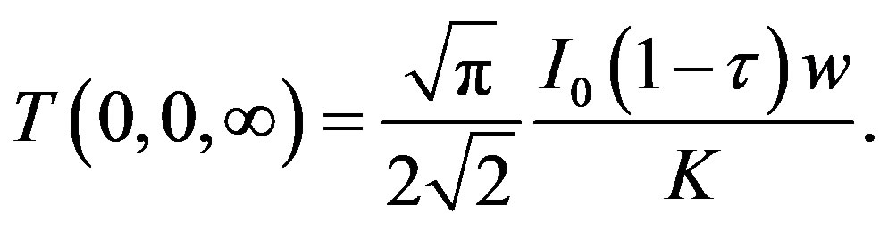 (6)
(6)
For comparison, Figures 3 and 4 show the calculated distribution of the stationary temperature fields in goldcoated aluminum and quartz samples for different values of K0 at a given power level.
The analysis of expression (5) confirms the localization of the temperature field, the intensity of which decreases sharply with increasing distance from the center of the irradiated region on the surface and deep inside the material.
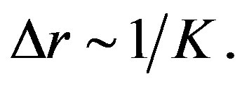
The half-width of the intensity distribution of the laser beam is several times narrower than the half-width of the corresponding temperature profile on the irradiated surface, and the broadening of the latter is determined solely by the thermal conductivity of the material:
If, during the laser exposure the melting point of the material is reached, then the optical surface is irreversibly deformed. By setting  in (4) and equating the obtained expression for
  to the melting temperature Tm of the material, we can estimate the value of the maximum laser intensity, which during the exposure time t0 leads to the melting of the surface layer:
 (7)
(7)
where  is a temperature
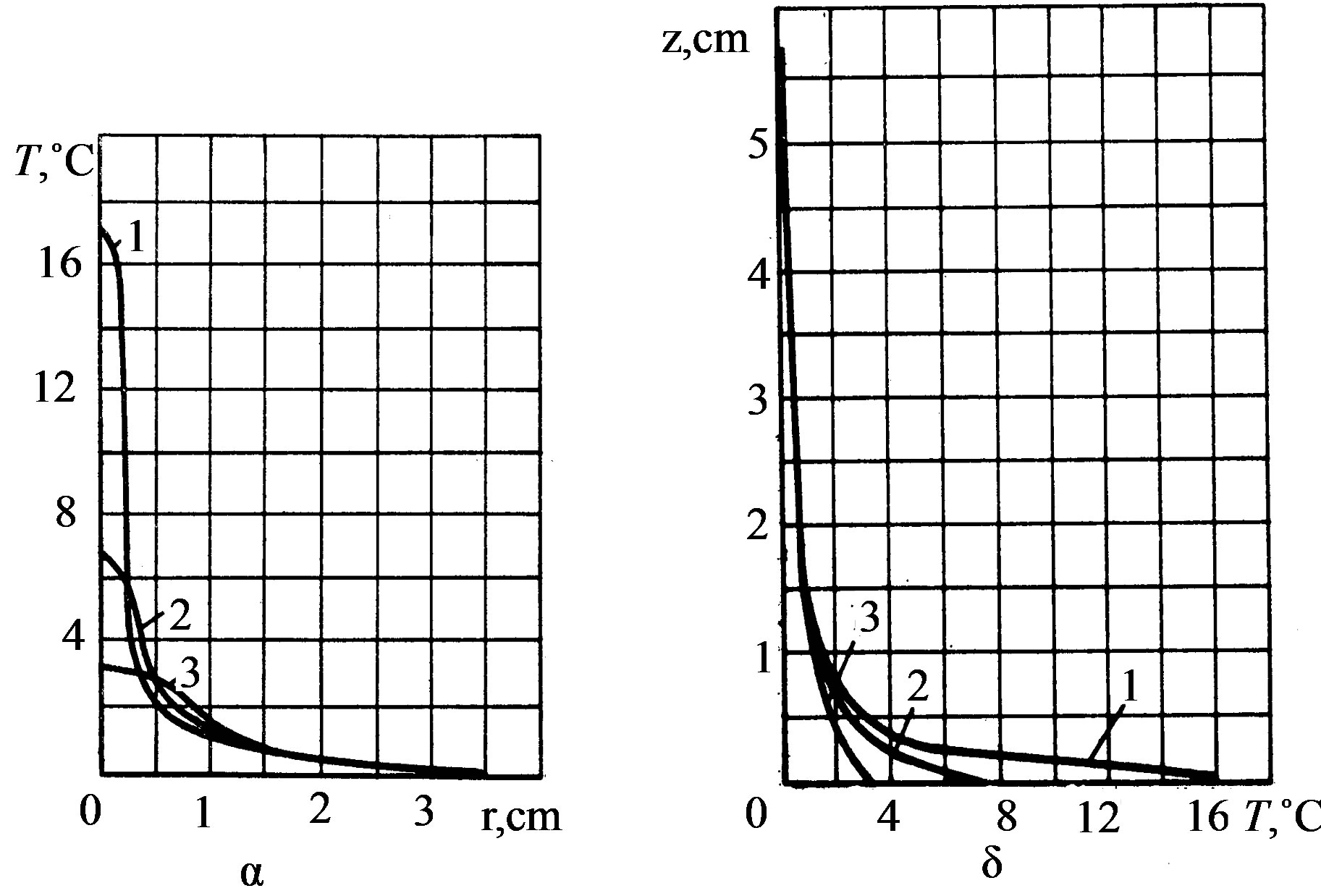
Figure 3. Temperature field distribution in the sample from Al covered by gold.
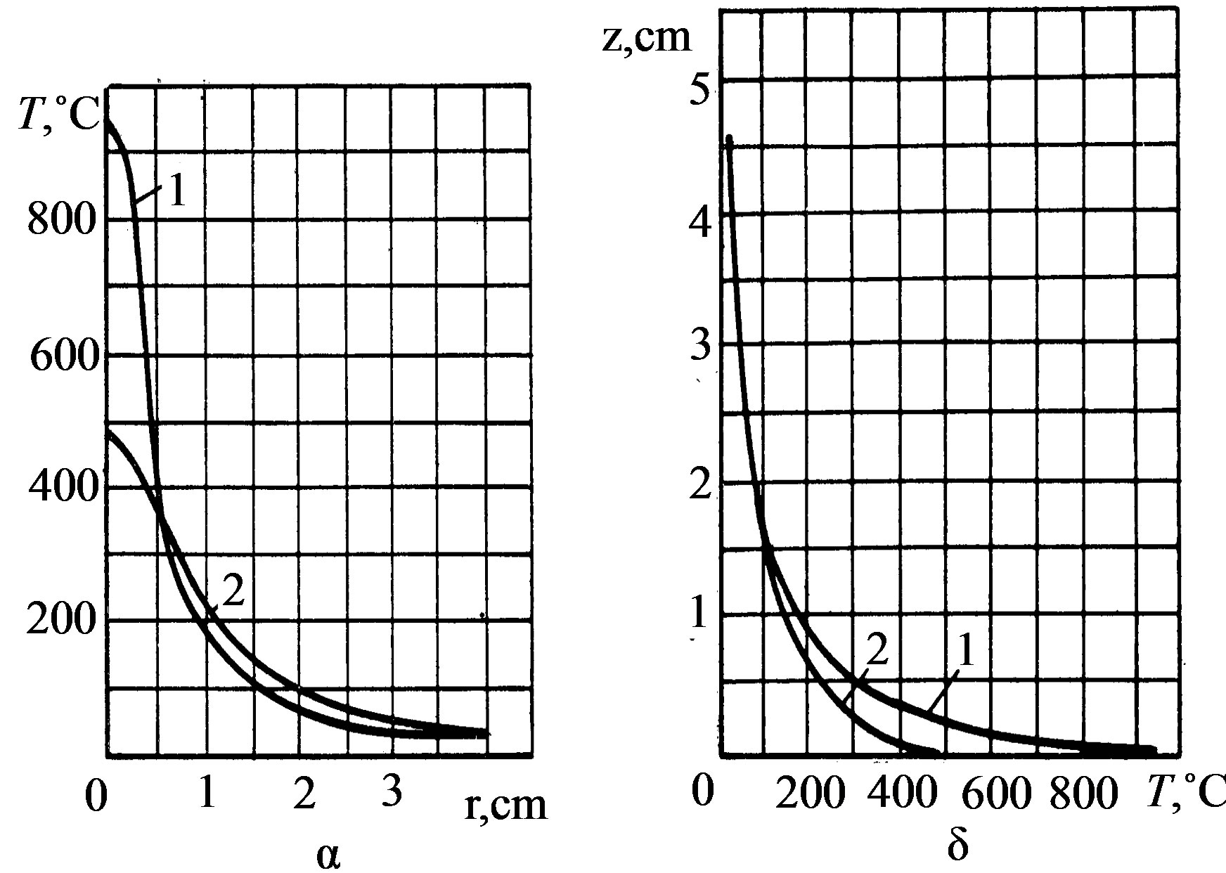
Figure 4. Temperature field distributions in the sample from quartz covered by gold.
function, which depends on the dimensionless parameter
(the Fourier number) 
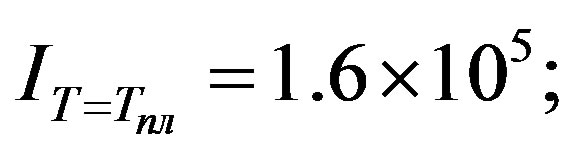
Thus, knowing the value of the temperature function at a given F0 (Figure 5), we can determine the maximum intensity of the laser radiation, which leads to the melting of the optical surface, for any material and any beam geometry at known values of the parameters Tпл, K, (Figure 6).
From this discussion it follows that for  the value of
  increases linearly with decreasing F0 and remains constant for
  In particular, for an aluminum sample with a reflectance
 , the maximum intensity, leading to the melting of the surface, is 8.6 × 10⁷ W/cm2 with a pulse duration t0 = 10−6 s and is virtually independent of the parameter
 . If the duration is t0 = 1 s, the values of the maximum intensity differ for different values of the parameter
  (
(
 W/cm2, and 0.2 cm, respectively
  сm), which is due to the mechanism of the material conductivity in the interaction process, resulting in a significant energy exchange between neighboring areas of the irradiated body. Note that

Figure 5. Temperature function ft dependence on Fo.
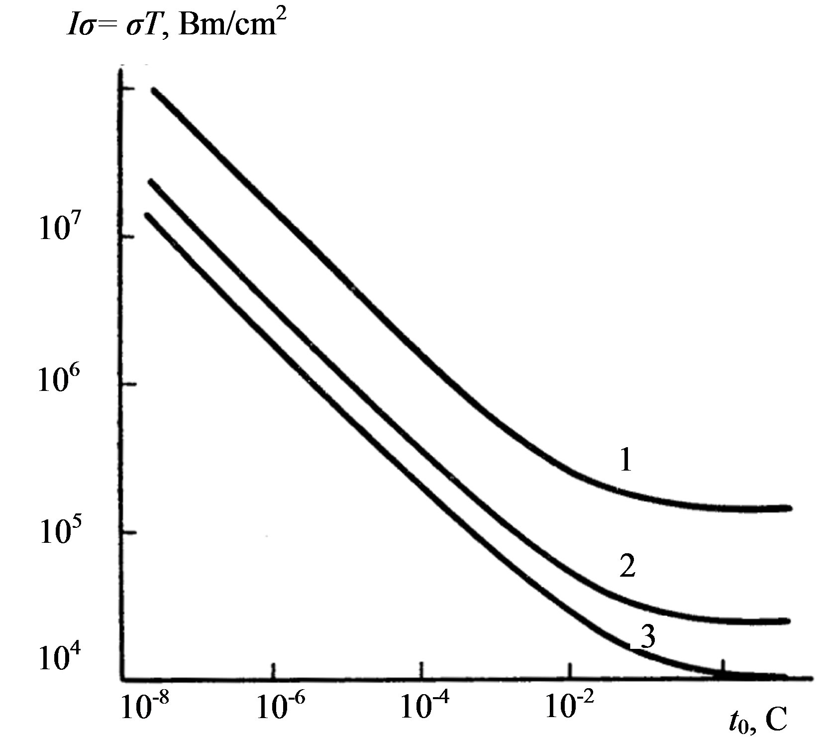
Figure 6. Maximum intensity of the laser radiation dependence on laser pulse duration for Ko = 50, 8.2.
this solution is valid for describing the processes preceding the thermal breakdown of the material. The nonstationary temperature field  causes a stress in the irradiated body, which also changes with time. Let us now define thermal stresses in a solid body.
5.2. Thermoelastic Stresses
In the quasi-static formulation, the problem of determining stresses in the half-space irradiated by an axisymmetric flux leads to the equation
 (8)
(8)
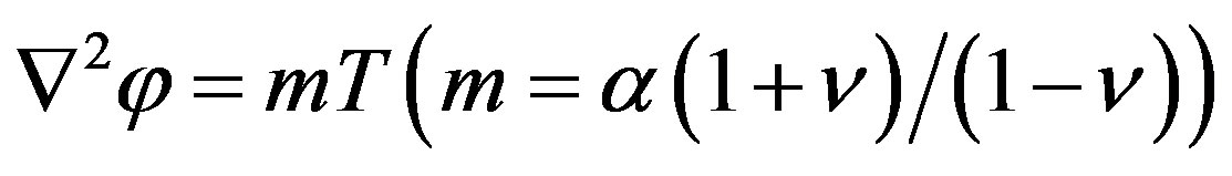
with the initial conditions  and boundary conditions at which
  Here
Here  is the thermoelastic displacement potential
 ,
,  is the coefficient of linear expansionand
  is Poisson’s ratio.
The solution of the problem is the sum of two fields of thermoelastic stresses: the fields  whose components of the stress tensor satisfy thermoelasticity equations, but do not satisfy the boundary conditions, and the fields
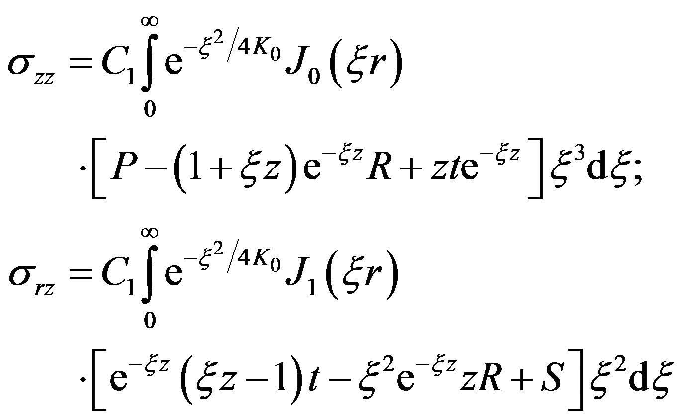
  whose stress components characterize the temperature-free solution of the corresponding classical theory of elasticity and satisfy the boundary conditions of the thermoelastic problem. After necessary transformations, we obtain the desired stress field:
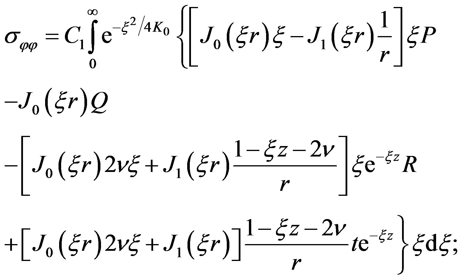 (9)
(9)
Here
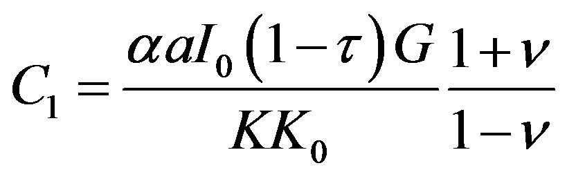
(G is the displacement modulus)


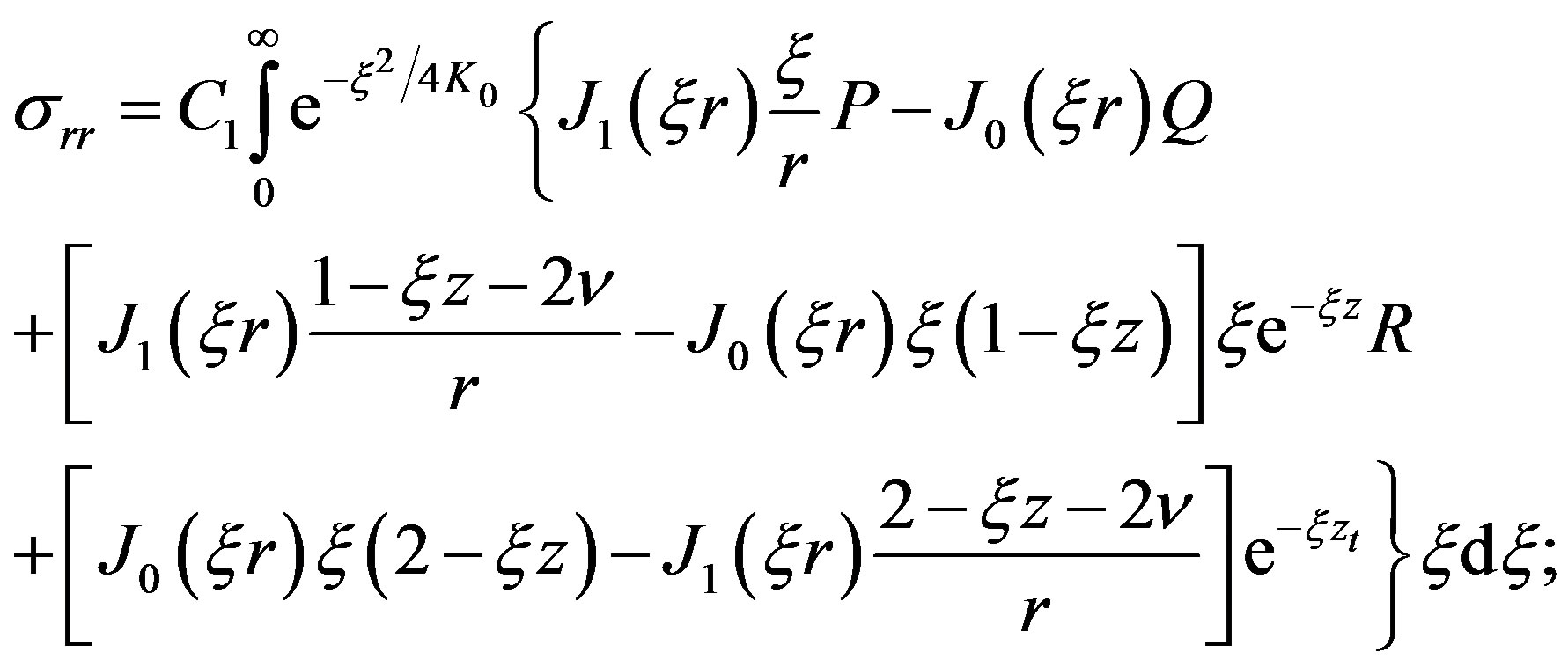
The expressions obtained show the variation of the stress field of the irradiated body during exposure to laser radiation. The maximum values of the radial and circumferential stresses are at a point r = 0 on the surface, where they are equal to each other, and can be written in the form:
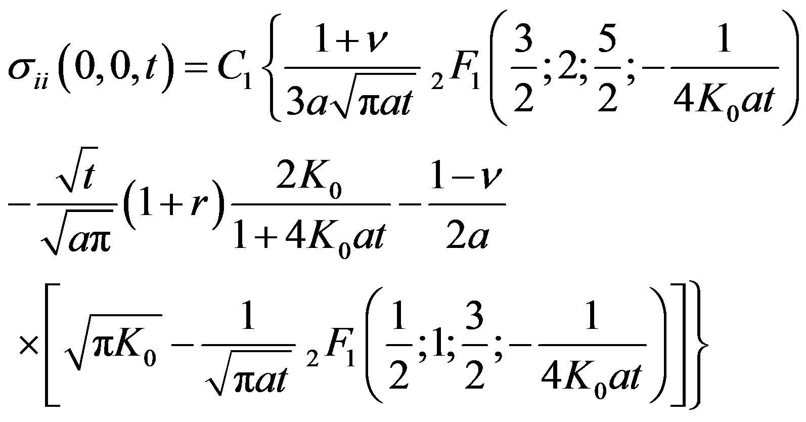 (10)
(10)
[ is the hypergeometric function].
Expression (10) allows one to evaluate the maximum laser intensity  leading during the irradiation time t0 to the achievement of the yield strength of the material, and to determine the maximum permissible duration of the laser pulse, corresponding to the given intensity. It is known that at intensities greater than the limit, plastic deformations arise in the surface layer, and after the termination of the laser pulse inevitable there appear residual stresses. Multiple repetition of the described process leads to a rapid destruction of the optical surface.
Figure 6 shows the dependence of the maximum laser intensity on the pulse duration for three values of the parameter K0 for a polished aluminum sample. Comparing the dependence obtained with the dependence  one can see that the maximum intensities, leading to a plastic yield of the material, are by 1.5… 2 orders of magnitude lower than the values corresponding to the melting of the material. In the case of CW exposure a stationary stress field can arise, which for the halfspace has the form
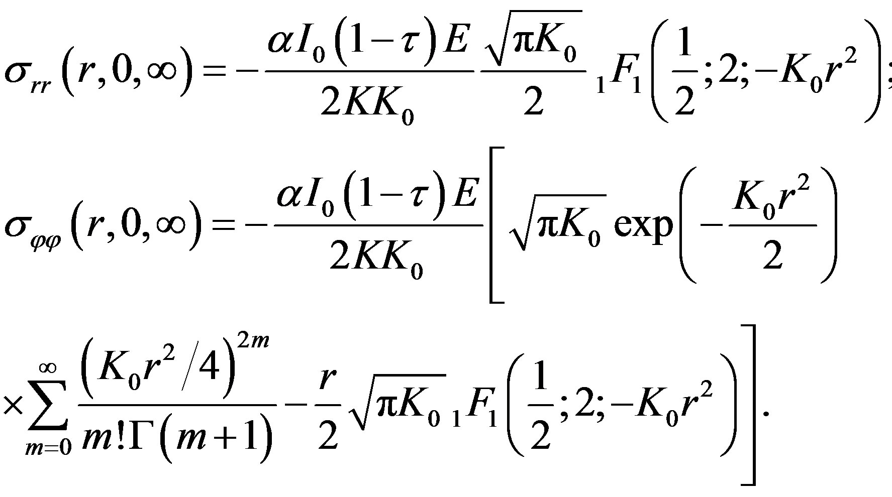 (11)
(11)
Here  is the degenerate hypergeometric function and E is Young’s modulus.
The components of the stress tensor  and
and  on the metal surface as a function of distance from the center of the irradiated region are shown in Figure 7. The change in the sign of the component
  at a distance
  seems interesting. This behavior of the stress field can lead to cracking of the material in the irradiation region and to its subsequent chipping.
Let us analyze now the other two components of the stress field in a solid body, arising during its exposure to a high-power light of finite duration, namely,  and
and  Of most interest is the consideration of the behavior of the component
 , because the component
  due to the axial symmetry of the problem everywhere on the axis is zero and
  has a maximum at point z0 > 0.
Figure 8 shows the dependence of the stress field component  at the axis
  of the aluminum sample during the exposure to laser radiation with intensity
  on the pulse duration t0. The feature

Figure 7. The components of the stress tensor  and
and  on the metal surface of Al as a function of distance from the center of the irradiated region
Figure 8. The dependence of the stress field component σzz at the axis (r = 0) of the aluminum sample during the exposure to laser radiation with intensity I0 exp(−K0r2) on the pulse duration t0.
of the behavior in the component  is the fact that as the exposure time decreases the maximum stress at point z0 passes through a maximum, and the coordinates decreases monotonically, approaching the surface. By equating the expression for the component
  at point z0 to the ultimate tensile strength of the metal, one can estimate the intensities at which the coating starts sagging during the exposure. Thus, the destruction of the optical surface by laser radiation can occur at intensities much lower than those required for its melting.
5.3. Surface Deformation
Let us determine the value of the displacement of the solid-body surface due to the impact of laser radiation. Displacement of the body surface can be represented as the sum of the derivatives in the coordinates of the thermoelastic displacement potential and Love’ function. The expression for the normal surface displacement that matches the temperature distribution has the form
 (12)
(12)
The displacement is negative, because the Z-axis is directed into the solid body. Profiles of the optical surfaces of various materials, deformed by the laser beam, are calculated at t0 = 1 s, K0 = 2 and P = 1 kW and are shown in Figure 9.
The graph shows that the minimum deformation
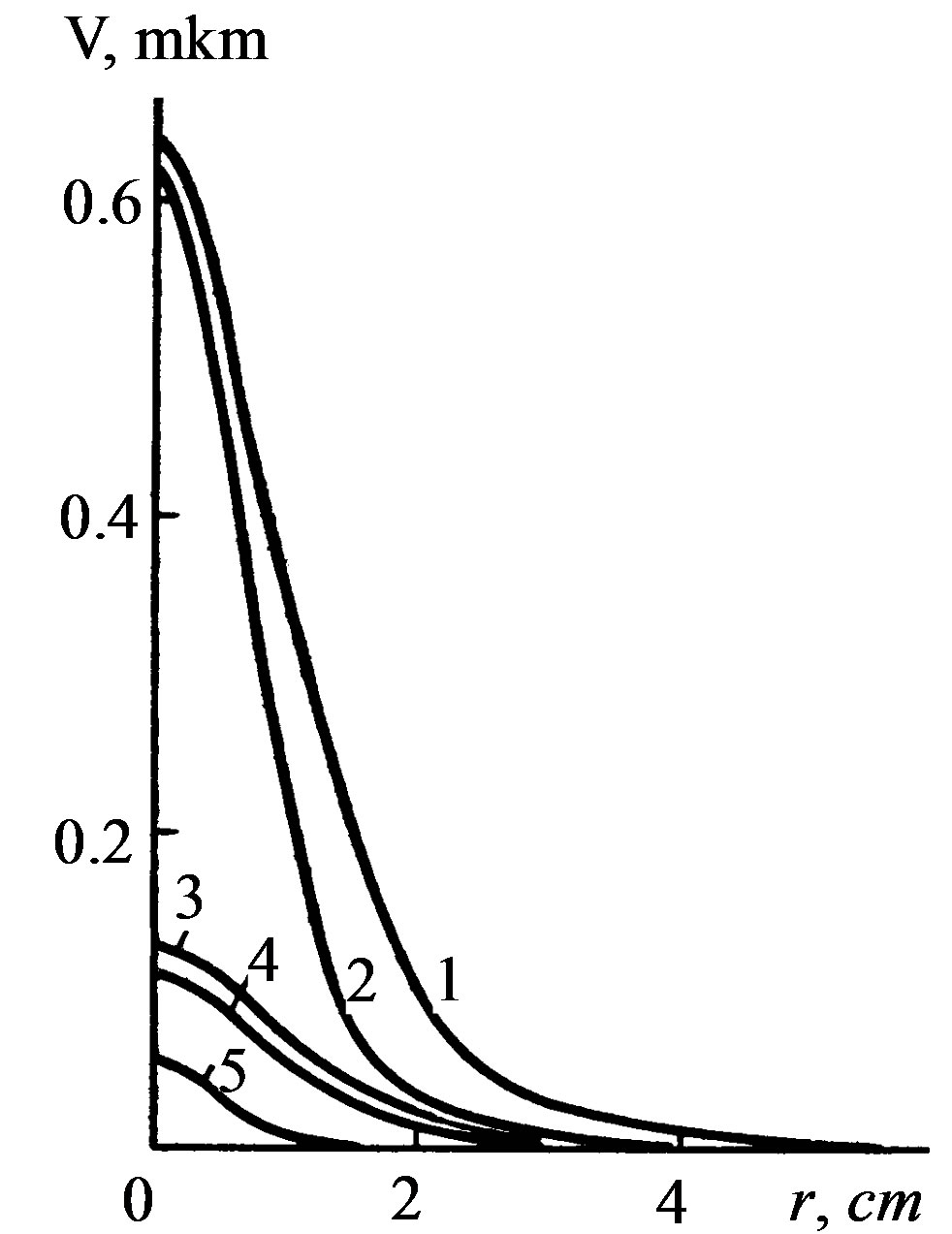
Figure 9. Profiles of the optical surfaces of various materials, deformed by the laser beam, are calculated at t0 = 1 s, K0 = 2 and P = 1 kW for Al-1, Ni-2, Cu-3, W-4, quartz with Au-5.
corresponds to a gold-coated quartz sample. This is explained by a slow increase in the material heating region due to the low thermal conductivity of quartz, and by the low value of its thermal expansion coefficient. However, the temperature of the surface of the quartz—gold sample is two orders of magnitude higher than the temperature of the copper sample. Equally significant is the dependence of the deformation of the irradiated surface on the energy distribution in the laser beam cross section. Figure 10 shows the deformation profiles of the surface of the nickel sample at different K0.
Consider the dependence of the surface deformation on the time of its irradiation. To do this, if r = 0 in (12) and the previously adopted notation is used, we obtain
 (13)
(13)
where
Thus, knowing the necessary parameters  one can determine the maximum deformation of the surface in the center of the irradiated region for any material and any exposure durations.
Note the following characteristics of the deformation process resulting from the consideration of the expressions obtained:
1) The process is local, and with decreasing exposure time the half-width of the deformation profile, exceeding the corresponding value of the laser beam for large t0, approaches the half-width of the energy distribution in the beam cross section, which causes deformation of the irradiated surface.
2) The value of the deformation increases rapidly at
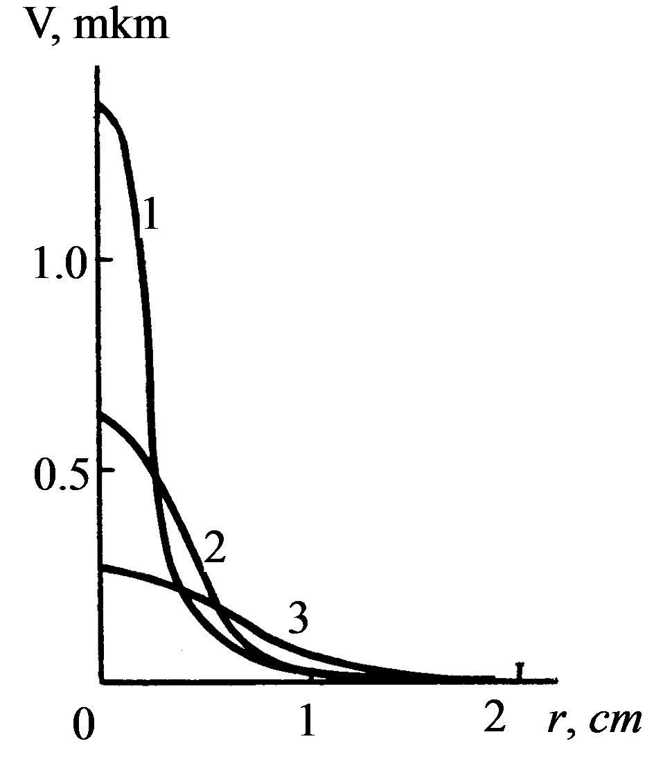
Figure 10. The deformation profiles of the surface of the nickel sample at different K0 = 50,8,2. P = 1 kW, t0 = 0,25c.
small values of the Fourier transform F0 and the rate of its increase is proportional to the intensity of the incident flux. When , the rate of change in the deformation decreases and the displacement of the surface continues to vary logarithmically slowly. The stage of the elastic behavior of the material is characterized by complete recovery of the initial state of the surface when terminating the laser action. However, in some cases, the deformations of the optical surface become inadmissible. Accounting for deformation is crucial for such laser systems as the quasi-optical transmission lines, telescopes, unstable resonators, and focusing systems.
The maximum of laser radiation can be estimated by equating V in (13) to the Vad, corresponding to the maximum admissible deformation of the surface, at which additional losses exceed some value fixed for each system
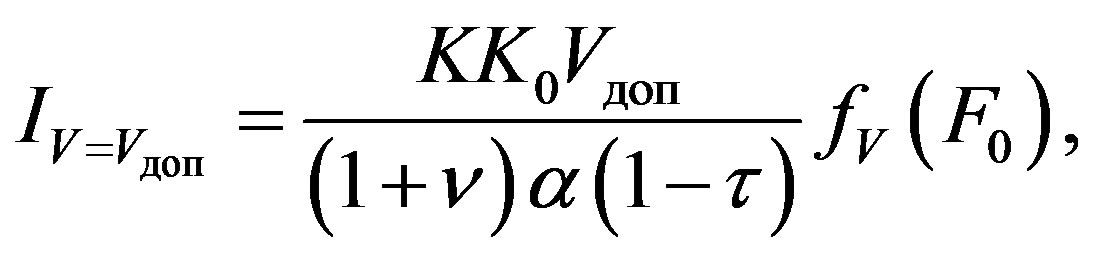 (14)
(14)
where  is the the displacement function.
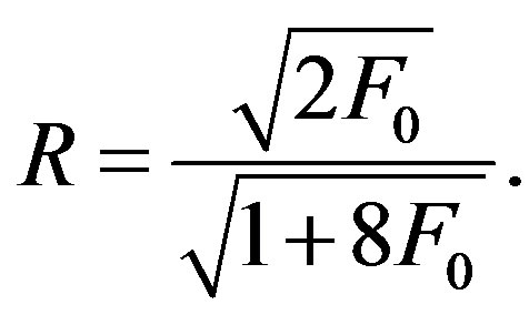
Thus, knowing the values of the function ,one can estimate the maximum intensity, resulting in admissible deformations of the optical surface of any material that obeys Hooke’s law. The dependence of the displacement on the dimensionless parameter F0 is shown in Figure 11. If
  the rate of a decrease in the function
  varies significantly, due to the saturation of the process of heat exchange by the material conductivity. The further slow drop in the displacement function is due to the increase in the value of the surface displacement from the effective heating region, the volume of which increases with F0.
Consider the behavior of the maximum intensities 
 as functions of the laser pulse duration
  for an aluminum sample (Figure 12), calculated for the beam with
  cm at
cm at 
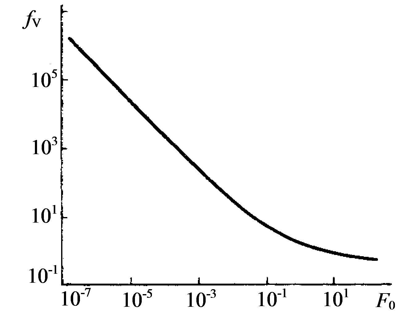
Figure 11. The dependence of the displacement function fv on the dimensionless parameter F0.
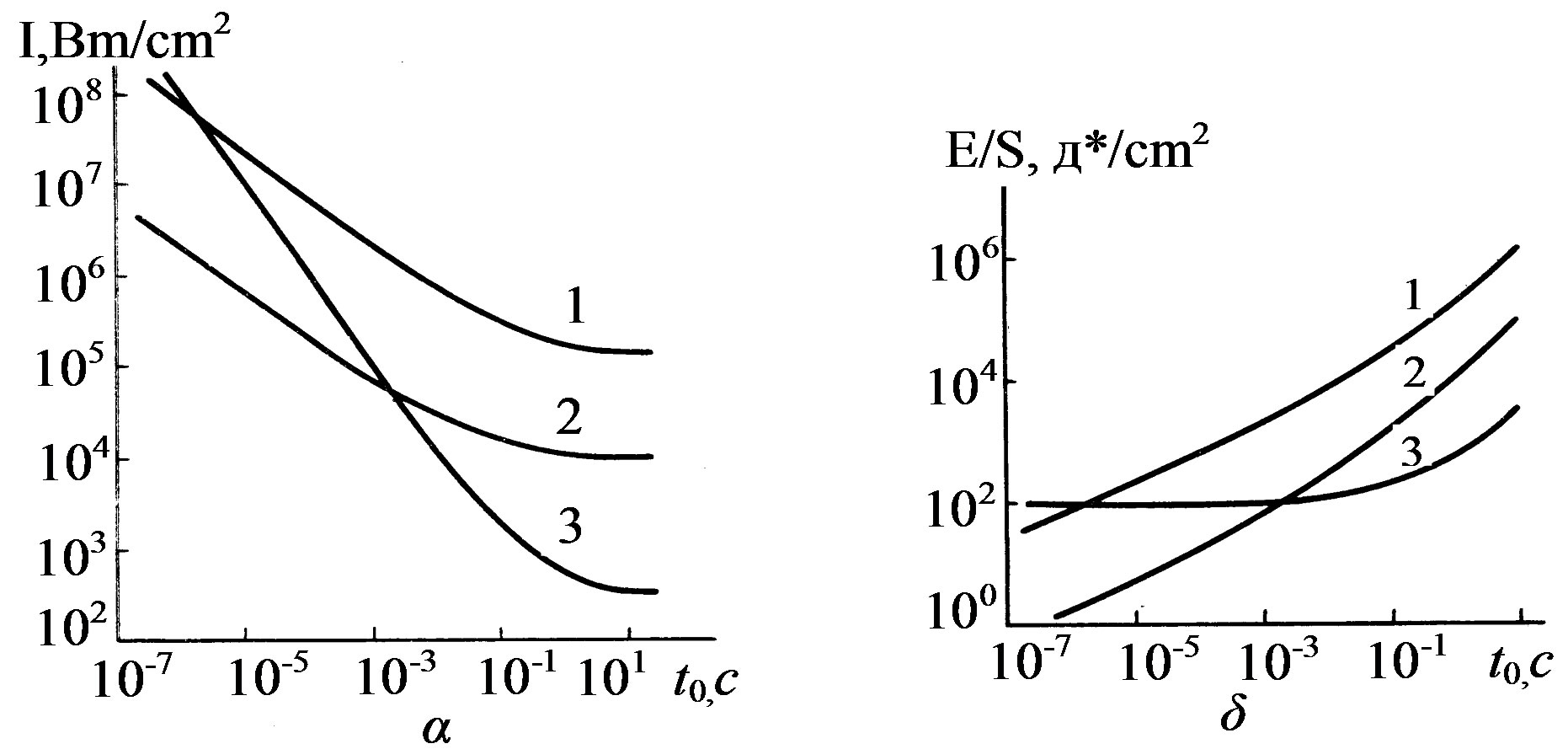
Figure 12. The maximum intensities  dependences on the laser pulse duration t0 for an aluminum sample for the beam with w = 1 cm at
 kg/cm2.
 kg/cm2 (the wavelength of the incident radiation is
 µm). For pulse durations
  and the given parameters of
  and
and , the main process, which limits the maximum value of the laser intensity, is the elastic deformation of the reflecting surface. With a pulse duration less than this, the transition of the material to the inelastic region becomes crucial, which is due the stresses (caused by irradiation) above its yield strength. It is however important to note that the pulse duration
  s for aluminum depends on the parameter
  of the incident beam and significantly decreases with its increase. Thus, for example, at
  cm the value of the pulse duration
 , for which the surface deformations should be taken into account, is
  s. Insignificance of the process of the reflecting surface deformation at low laser pulse durations is explained by the smallness of the effective heating of the material.
However, it should be noted that these estimates are valid for ideal surfaces in a vacuum, because the presence of air and slight contamination of the irradiated surface can lead to the breakdown of the gas near the surface and, consequently, to its destruction at laser intensities that are less than the estimated ones.
6. POROUS STRUCTURES IN HIGH POWER OPTICS
The feasibility of using structures with open porosity for cooling heat-stressed laser mirrors was justified for the first time theoretically and experimentally in [21]. An increase in the optical damage threshold of laser reflectors based on porous structures was provided by a “minimum” thickness of the separating layer (tens of microns), by the heat transfer growth via an increase in the coolant circulation velocity pumped through the structure and by the effect of the significant development of the surface [21-26]. We have shown experimentally that the placement of special porous structures in made it possible to increase (by ~ 9 times) the effective coefficient of convective heat exchange and to reach ~ 22 W/cm2 × deg. The test results of water-cooled laser mirrors that are based on the structures with open porosity first indicated the possibility of removal of high heat flows at low values of the mirror surface deformations. The maximum density of the heat flow being removed, which does not lead to destruction, is  kW/cm2, and at q = 2 kW/cm2 the
  µm/20, where λ value of thermal deformation was ~λ/20 µm. A further increase in the optical damage threshold of cooled mirror surfaces can be achieved by optimizing the parameters of the porous structure, the appropriate choice of the coolant and the rational design of its inlet and outlet. The development of such “optimal” laser reflectors requires a detailed study of heat and mass transfer in porous structures, which are currently insufficiently studied. Let us consider some aspects of this problem.
6.1. Temperature Field
The temperature fields in the porous structures are calculated in the one-dimensional formulation under the following assumptions: the incident radiation is uniformly distributed over the irradiated surface; the thickness of the porous layer  is much greater than the depth of heating, which makes it infinitely large
  and allows consideration of the half-space model; and the temperature and velocity of the flow through the thickness of the porous layer is constant.
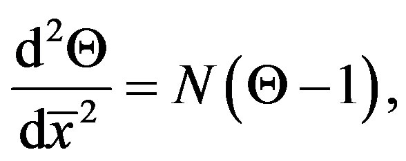
Then the heat transfer equation, which describes the temperature distribution over the thickness of the porous layer, can be written as
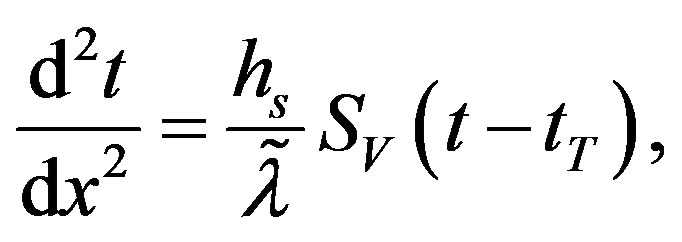 (15)
(15)
where x is the coordinate; t, tT is the temperature material (skeleton) of the porous structure and the coolant, respectively; hs is the heat transfer coefficient between the material structure and coolant;  is the skeleton thermal conductivity along the axis x; and SV is heat transfer surface per unit volume. Equation (1) can be written in the dimensionless form:
 (16)
(16)
where  and
and  are the dimensionless temperature, coordinates and parameters, respectively;
  is the average particle diameter in the structure;
  is the modified Nusselt number, which characterizes the ratio of convective to conductive heat transfer across the skeleton boundary; and
  is the dimensionless parameter characterizing the structure.
The boundary conditions of equation can be written in the form:
 (17)
(17)
where  is the dimensionless heat flux density; q is the heat flux density transmitted through the separating layer.
Solution to equation) with the boundary conditions (17) has the form:
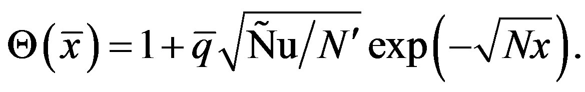 (18)
(18)
It follows from (18) that the rate of temperature decrease over the thickness of the porous structure is determined by the parameter .
.
We write down some relations required to calculate the thermal characteristics of laser reflectors. The temperature of the separation layer at the interface with a porous substrate  has the form:
 (19)
(19)
The maximum heat flux density, removed from the reflector due to convective cooling, follows from the condition of equality of the coolant  and the boiling point
  at appropriate pressure
  and has the form:
 (20)
(20)
The degree of heat transfer in a porous structure as a result of the flow circulation and the surface development is determined by the coefficient , which characterizes the ratio of the amount of heat removed by the coolant in the structure under consideration, to the amount of heat that would be removed directly from the cooling surface of the separation layer by the coolant when it flows in a Δ channel of depth
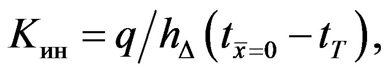
where  is the coefficient of convective heat transfer in the coolant flow in a slot gap of size Δ. For example, for the turbulent regime of the coolant flow the Nusselt number
  has the form
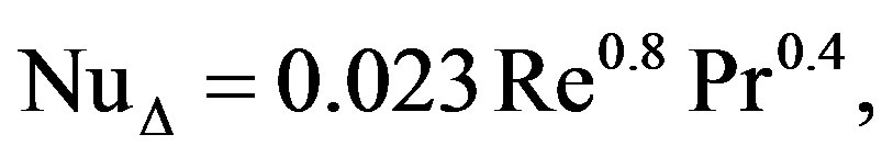
where Re, Pr are the Reynolds and Prandtl numbers.
Let us introduce the coefficient of heat transfer due to the flow turbulence  where hs is calculated from the condition that the flow of coolant circulating through the reflector is constant. Then,
  depending on the structure type and parameters and on the thermophysical properties of the coolant is calculated as follows:
 (21)
(21)
where  is the coefficient of ribbing of the cooled surface of the separation layer.
Equation (18) allows one to find the depth of the structure heating that defines the minimum possible thickness of the porous layer, conventionally assuming that the heating ends at the coordinates  where the skeleton and the coolant temperatures differ by 1%:
 (22)
(22)
In the case of removal of the maximum heat flux densities, the depth of heating is
 (23)
(23)
Thus, relations (18) - (23) allow one to calculate the temperature fields and thermal characteristics of the cooled laser reflectors. In combination with the expressions describing the flow hydrodynamics, they are the basis for optimizing the parameters of porous structures, ensuring minimal thermal deformations of mirror surfaces or, if necessary, the maximum heat flux, removed in the case of convective cooling.
6.2. Convective Heat Transfer
The regime of the coolant flow in porous materials, which are of interest for high-power optics, is a transition between laminar and turbulent regimes; in this case, the calculation of the heat transfer coefficient between the skeleton and the coolant is very difficult despite numerous experimental data. The lack of a unified approach to processing of the experimental results and the inability to accurately determine such important characteristics as the SV, ds etc. make the calculation of heat transfer of liquid drops in various types of porous structures with geometrical parameters that vary widely. Therefore, these equations can only be recommended as a first approximation to calculate the volumetric heat transfer coefficient in structures that are identical to the tested ones, and to gas coolants. It is generally accepted that the criterion equation of the interporous convective heat transfer for gases and droplets has the form:
 (24)
(24)
where c and n are the constants depending only on the structural characteristics of the porous material.
Based on the experimental data of papers we analyzed the dependences of c and n on the structural characteristics of porous materials for which the latter are quite authentically known; as a result, we found that c and n depend mainly on the bulk porosity . Thus, relation for the dimensionless Nusselt number with account for correlation expressions с(ΠV) and n(ΠV) allows one to calculate the coefficient of convective heat transfer in a porous material.
6.3. Hydrodynamics of a Single-Phase Flow
The temperature field and thermal deformation of the reflector are largely determined by the discharge of the coolant pumped through a porous layer, which depends on the hydrodynamic characteristics and conditions of the coolant inlet and outlet. Hydrodynamic characteristics of a single-phase fluid flow in porous materials, mainly in the region  were studied in many experimental works. The expressions proposed by different authors can be used to calculate the hydrodynamics of the flow in materials that has an identical structure to the samples studied.
In general, the hydrodynamics of the flow in porous materials is described by the modified Darcy’s equation (Dupuit – Reynolds – Forchheimer):
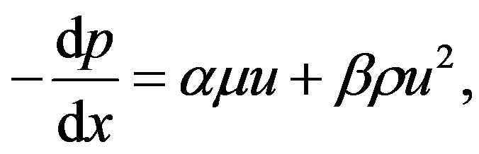 (25)
(25)
where p is the flow pressure; u is the filtration rate, equal to the ratio of the specific coolant discharge G to the density ρ; and β are the viscous and inertial is coefficient of dynamic μ resistance coefficients, respectively; and viscosity of the coolant.
From Equation (25) we obtain the equation for the coefficient of friction, Cf, in the form
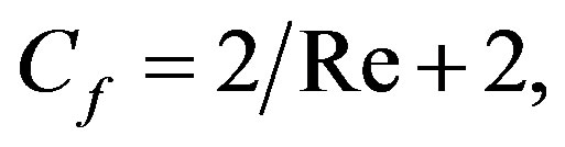 (26)
(26)
where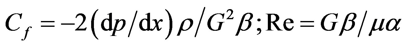 (the characteristic size β/α).
Practical use of relation (26) for the calculation of the hydrodynamics of the flow in different types of porous materials, whose structural characteristics vary widely, is hampered by lack of information about the coefficients α and β, which are usually determined experimentally.
Well known a slightly different approach to the calculation of Cf: as a characteristic size they used , where K is the permeability coefficient, characterizing the hydrodynamics of the flow according to Darcy’s law
 , then
 (27)
(27)
The relationship parameters α and β between the coefficients c and K can be represented as  and
and .
.
Parameter c is a universal constant for identical porous structures. For example, for all the materials made of metal powders with spherical or close-to-spherical particles we have , and for materials made of powders of arbitrary shape we have
 . Thus, in the future when calculating the hydraulic characteristics of the structures we assume
 , although in our case this provides a somewhat higher value of the coefficient of friction.
Research conducted with fibrous materials, foams and structures of the layers of particles of arbitrary shape has shown that the parameter c for these materials is relatively small. This is explained by the fact that c, characterizing the fraction of inertial losses, depends largely on the nature of the wake formed behind solid particles due to the flow, and the wake depends on the type of porous structure.
The presence of the free ends (further turbulizing the flow) in metal-fibrous structures increases c; therefore, for a relatively short fibers, l/d = 50 - 100, с ≈ 0,132.
The permeability coefficient K, which is a structural characteristic of a porous material, does not depend on the flow regime and is determined experimentally from Darcy’s law. In connection with the development of works in the field of heat pipes, many experimental data are currently available to determine K for powder and metal fibrous structures. According to our experimental data, the relation of the permeability coefficient for metal fibrous structures with bulk porosity has the form:
 (28)
(28)
where A and m are the coefficients depending on the relative length of the fibers l/d. Similar expressions can be obtained for powder materials.
In addition, the permeability coefficient is calculated from the known Carman-Kozeny relation:
 (29)
(29)
where  is a constant depending on the structure.
Expressions (27) - (29) were used to determine the hydraulic characteristics of the power optics elements, made of porous materials based on metal powders and metal fibrous structures.
6.4. Effect of the Coolant Inlet and Outlet Conditions on the Hydraulic Characteristics
Usually, in cooled laser reflectors the coolant is supplied to and removed from the porous structure through evenly distributed alternating channels, which are made in the form of slots or holes on the cooling surface. With a slotted inlet, a more uniform velocity field of the coolant and a minimum differential pressure required for its pumping are provided. In the case of inlets and outlets in the form of alternating holes we may deal with a significant non-uniformity of the velocity field in calculating the flow in radial directions. This leads to additional pressure drops in the circulation of the coolant, which are considered by the coefficient Kг; in this case, the total pressure drop in a porous layer has the form
 (30)
(30)
where Δр is the pressure in the case of a uniform velocity field.
Under the assumption of uniform injection (outflow) of the coolant in the radial directions in the regions of supply (outlet) restricted by the region  (s is a step between alternating holes, r0 is the radius of the hole), the coefficient Kг, characterizing the influence of collector effects on hydraulic resistance during the motion of the fluid in a porous layer, can be written as:
 (31)
(31)
Here G is the mass flow rate of the coolant, F is the area of the exposed surface, n is the number of channels for the supply (outlet) of the coolant, and  is a relative spacing between the holes. One can see from Equation (31) that Kг depends both on the geometric characteristics of the supply and removal of the coolant (on a) and on G; with increasing a and G, the coefficient Kг increases. Thus, the coefficient Kг is characterized by design excellence of the inlet and outlet system of the mirror coolant.
With the known Kг the total pressure drop in the porous layer is calculated by the formula (30), taking into account the expression for calculating р:
 (32)
(32)
where v = Gs/(ρFΔ) is the coolant filtration rate.
6.5. Thermal Conductivity
As for the problems of cooling of power optics elements, of interest is to study the thermal conductivity of a porous material skeleton without account for the thermal conductivity of the coolant. Taking into account the summarized the results of numerous experimental studies of thermal conductivity of materials of various structures and showed that the effective thermal conductivity depends not only on the volume porosity, but also on such factors as the sintering behavior of the material, the size and shape of the primary particles, pressing and sintering technologies, etc., which leads to a large scatter in the data and makes it difficult to generalize the results. Practical data are summarized in the form of the dependence  (ПV) for the samples, manufactured using the single technology and the same type of material. Analysis of experimental results shows that for the calculation of a wide range of porous powder materials can be based on the Odolevsky equation:
 (33)
(33)
where λк is the thermal conductivity of a compact material.
Effective thermal conductivity of metal fibrous felt structures may have a considerable anisotropy depending on the direction of the fibers in the felt. Thus, on the basis of  is generalized by the relations:
 (34a)
(34a)
 (34b)
(34b)
where  is the effective thermal conductivity in the direction parallel to (34a) and perpendicular (34b) to the felt-making plane. In the latter case one can also use the expression
 (35)
(35)
Expressions (34b) and (35) satisfactorily approximate the experimental data and can be used in the determination of the thermal characteristics of cooled laser mirrors, made of metal fibrous structures. In this case, expression (34b) describes the upper limit of the experimental data (an optimistic estimate), and (35)—the lower (a pessimistic estimate).
6.6. Estimate of the Thermal Deformation
In general, thermal deformations of a mirror are calculated by using the temperature field of the separating layer and the porous base and the known conditions of their attachment. The exact solution of this problem of thermal strength under real conditions of the reflector exposure is very difficult.
To estimate the low distortions of the optical surface, which are characteristic of deformation of power-optics elements, one can make the assumption of free expansion of the porous base and the separating layer according to the temperature fields. Then, the thermal deformation of the mirror surface W is the sum of extensions of the separating and porous layers:
 (36)
(36)
where αp and αn are the temperature coefficients of linear expansion of the separating and porous layers, respectively;  is the dimensionless temperature; t0 is the coolant temperature at the inlet of the reflector; and t1 and t2 are the temperatures of the outer and inner surfaces of the separating layer, respectively.
It follows from equation (36) that the higher the coolant flow rate, the lower the W. The maximum deformations of the optical surface are realized in the region of the outflow of the coolant from a porous layer, the heating value of the coolant through the slot channels having the form

where GT is the heat capacity of the coolant.
6.7. Results of Thermal Characteristics Calculations
The above-derived expressions describing the processes of heat and mass transfer in porous structures, were used to calculate the characteristics of cooled laser mirrors with the coolant inlet and outlet system in the form of uniformly (with a step s) alternating holes; the distribution of the heat load on the surface of the reflector was assumed uniform.
Figure 13 shows the qualitative dependence of the deformation on the maximum density of the heat flow being removed (the constant ПV at a constant ds) for two selected regions of the reflector, corresponding to the regions of injection W1(qmax) and outflow W2(qmax) of the coolant. Varying the average grain size ds (or the diameter of the fiber), we can construct a family of curves, characterized by a constant value of ds and variable porosity ПV, for reflectors with the same type of capillary structure. The curves are plotted at a constant pressure drop and by taking into account the coolant heating in the porous layer; the temperature of the coolant at the inlet temperature was assumed equal to the temperature of the final finishing of the mirror. The deformation of the optical surface in the coolant outflow region obeys W2 > W1. Crucial to the selection of the structural characteristics of the porous material is curve 2, and the difference between curves 1 and 2 characterizes the degree of the cooling system perfection. The curves are the envelopes of the working thermal deformation characteristics of a family of reflectors with this type of structure. Performance characteristic of the reflector with a given porosity structure ПV is obtained by connecting the
Figure 13. Qualitative dependence of the thermal deformation on the maximum heat flux density removed from two regions of the reflector, corresponding to the region of the coolant injection (1) and outflow (2).
straight line from point C with the origin of the coordinates. Point C corresponds to the maximum heat flow, removed due to convective cooling, and the line segment OC is a dependence of thermal deformations of the mirror surface on the heat load. In general, curve 2 has two main points: point A corresponding to optimal porosity  which facilitates removal of the maximum heat flux density for the selected grain size, coolant pressure drop, and coolant supply and removal conditions; and point B (the point of tangency of curve 2 with the straight line from the origin of the coordinates) corresponding to the porosity
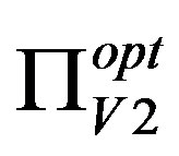 , for which in the porous structure the optimal thermal distortions of the mirror surface are realized.
The choice of material and the basic parameters of the structure (ds, ПV) must be based on a comparison of a family of curves 2 with possibilities of obtaining the desired porous structures and separating layers.
Figures 14 and 15 present the results of numerical cal-
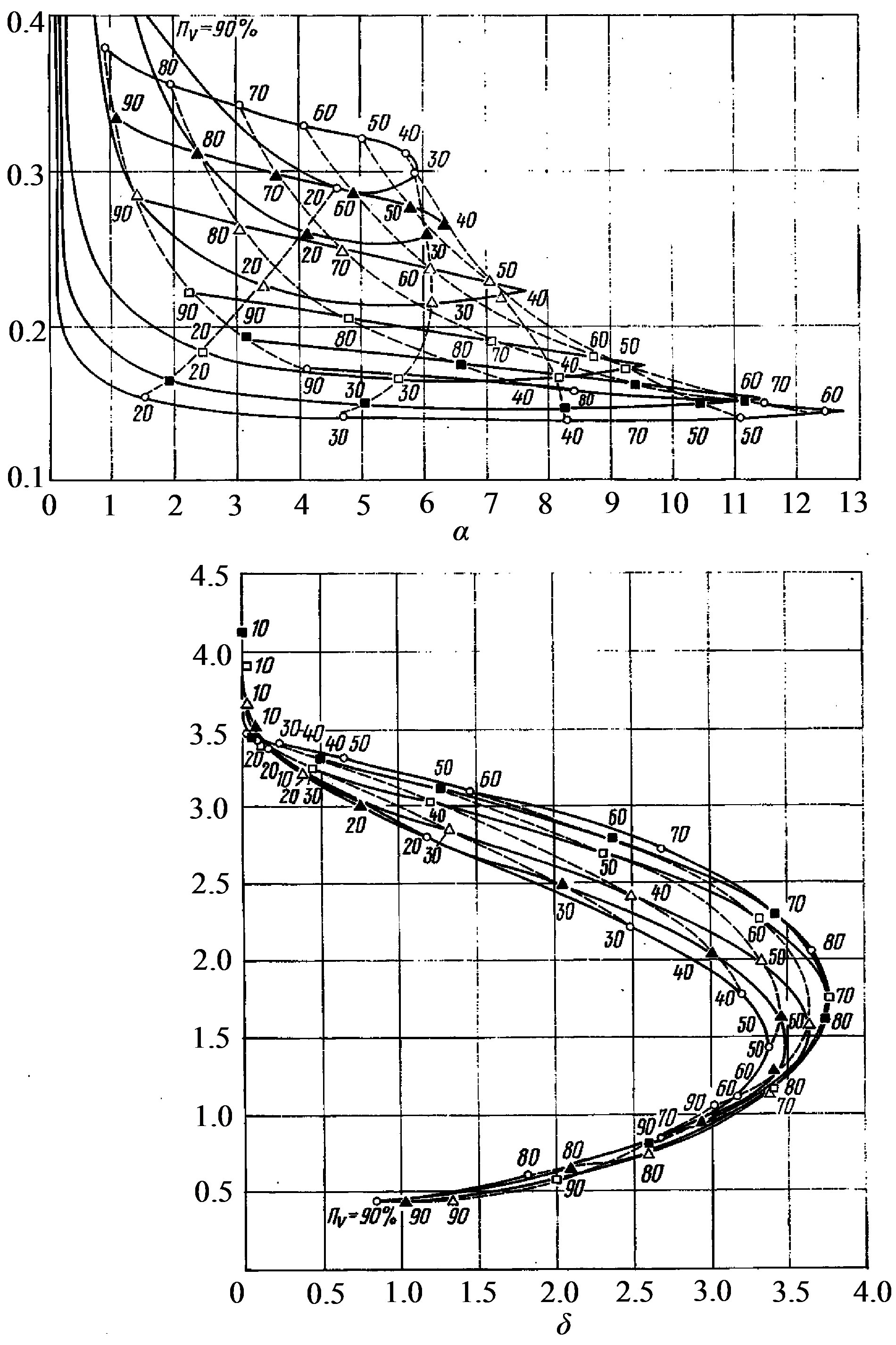
Figure 14. Nomograms of thermal deformation characteristics of a family of water-cooled reflectors made of copper (a, b) and molybdenum (c, d) powders for the injection region (a, c) and the outflow region (b, d); points in this and other figures correspond to the following particle diameters or felt: #—20, #—30, #—50, #—150, and #—200 µm.
Figure 15. Nomograms of thermal deformation characteristics of a family of water-cooled reflectors based on porous structures made of copper (a, b) and molybdenum (c, d) felt: the region of the coolant injection (a, c) and region of the coolant outflow (b, d).
culations of thermal deformation characteristics of a family of water-cooled reflectors with porous structures made of the widely used copper powders (Figures 14(a) and (b)) and molybdenum powders (Figures 14(c) and (d)), illustrating the capabilities of the method. The average grain size and bulk porosity varied between 20 ≤ ds ≤ 200 µm and 0, 1 ≤ ПV ≤ 0,9.
One can see from Fig. 14 that the maximum heat flux densities are as follows: in the region of the coolant inlet qпр1 = 12.8 kW/cm2, in the region of the coolant outlet qпр2 = 3.75 kW/cm2, with W1 = 0.1 - 0.4 µm, and W2 = 0.4 - 3.5 µm. In the region of the maximum heat flux density W2 = 1.5 - 2 µm, which is in most cases much higher than the maximum allowable deformation of the reflectors for CO2 lasers.
With the increase in coolant flow (Figure 14(b)) W2 can be dramatically reduced by using the materials with high bulk porosity (0.7 - 0.8) and the transition to a larger grain size. In this case, qmах = 2 kW/cm2 at W = 0.5 µm. Powder-material structures with ПV > 0,75 for the power optics are very difficult to produce. With a decrease in porosity to the real values (~0.6) the heat flux densities being removed will be ~ 1.4 kW/cm2 at a 0.5 µm deformation. Note that increasing the coolant flow rate is also achieved through rational design of the coolant inlet and outlet system, providing a more uniform distribution of the coolant along the cooling surface.
One can see from Figures 14(c) and (d) that the use of porous molybdenum allows an approximately four-fold decrease in the level of thermal deformations of mirror surfaces in both the first and second regions; in this case qпр somewhat decreases: qпр1 = 7,8 kW/cm2, (qпр2 = 2,8 kW/cm2). For this structure (Figure 14(c)) in the implementation of the maximum removed flows the arising thermal deformations are below the characteristic optical damage thresholds of the reflectors for CO2 lasers. For example, a structure with ΠV = 83% и ds = 20 µm facilitates the removal of qmax = 2.8 kW/cm2 at W = 0.45 µm. With increasing the coolant flow  (Figure 14(b)), qmax decreases. In this region the level of heat flows to be removed can be increased by the use of materials with the larger size of the particles; for example, the molybdenum powder structure with ΠV = 83% и ds = 20 µm facilitates the removal of qmax = 2.1 kW/cm2 at W = 0.23 µm.
Figure 15 shows the thermal deformation characteristics of the reflectors with porous structures made of copper (Figures 15(a) and (b)) and molybdenum (Figures 15(c) and (d)) felt. One can see from Figures 15(a) and (c) that the transition to metal fibrous structures leads to a significant (~1.7) decrease in qпр, which is associated with a decrease in the effective thermal conductivity of these structures compared to powder structures.
In regions of the coolant outflow (Figures 15(b) and (d)) the maximum heat flux densities are on the same level as for the mirrors with powder structures; however, an increase in the coolant flow leads to a strong dependence of W on ПV and to less sensitivity to the diameter of the initial fibers. Deformations corresponding q# are approximately two times lower compared to the powder structures: for copper and molybdenum reflectors W = 1.2 and 0.3 µm at qпр = 3,9 kW/cm2 and qпр = 2.6 kW/cm2, respectively. For mirrors with a copper fiber structure the heat flux densities, which can be realized with W = λ/20 (where λ = 10.6 µm), of 2.4 kW/cm2, are 2.4 kW/cm2, which exceeds the corresponding level of qmax for powder materials. Thus, the use of metal fibrous structures for producing power optics elements is very promising; for example, the structure of molybdenum fibers with a diameter of 100 - 200 µm and a porosity of 50% - 60% qmax = 2.2 kW/cm2 at W ≈ 0.15 µm. In addition, the possibility of obtaining materials with high ПV (70% - 80%) makes it possible to manufacture optimal reflectors.
6.8. Comparison of Theoretical and Experimental Results
We have compared the calculation results of thermal mirror-surface deformations of the laser reflector based on a porous copper-powder material with the experimental data.
Figure 16 presents the results of experimental studies of thermal deformations of a water-cooled mirror as a function of the density of the heat flow removed, and the results of calculation of the maximum thermal deformation characteristics in the region of the coolant removal for a family of reflectors with a 55% - 70% porosity. Straight lines are the calculated characteristics of the tested reflector for the maximum porosity of 60% and 62%. It is seen that there is good agreement between theoretical and experimental data [36-45].
Figure 16(b) shows the calculation of the thermal deformation characteristic of a family of reflectors in the region of the coolant inlet, which, like the curve in Figure 16(a), is obtained for the cooling surface temperature of the separating layer equal to 100˚C. It follows from Figure 16(b) that qmax = 8,2 kW/cm2, in good agreement with the experimental data .
Note in conclusion that this method of predicting the thermal and deformation characteristics of porous laser reflectors offers optimized type and parameters of the structure to ensure the necessary removal of heat fluxes at the admissible values of the distortion of the mirror
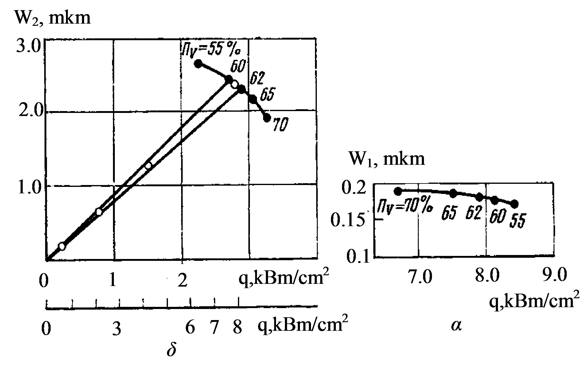
Figure 16. Thermal deformation characteristics of a family of water-cooled reflectors based on porous structures made of copper powder: the region of the coolant injection (a), the region of the coolant outflow (b) (filled circles are the theory, light circles are the experiment).
surface. The results of theoretical and experimental studies suggest that water-cooled laser reflectors with porous structure have a high optical damage threshold. With the accumulation of new experimental data on convective heat transfer and hydrodynamics of flows in porous structures the latter can be quite easily introduced into the calculation algorithm.
7. PURSUIT OF POWER OF SEMICONDUCTOR LASER STRUCTURES
One of the brightest and most promising implementations of the ideas of cooled power optics is now the introduction of forced heat transfer in high-power semiconductor lasers. Currently, this type of laser has the highest efficiency reaching 80% - 90%. Modern manufacturing technologies of semiconductor structures made it possible to significantly increase the laser lifetime, which is tens of thousands of hours of continuous operation. The variation of the semiconductor material composition can change the wavelength range of the radiation from the near-IR to the UV. They are very compact, reliable and easy to operate. The power output can be increased by the simultaneous use of a large number of laser diodes, which are formed in one-dimensional or two-dimensional effectively cooled structures.
Cooled laser diode assemblies possess almost all the remarkable properties of single semiconductor lasers: high-density, high reliability, long lifetime (up to 1012 cycles). These lasers have much smaller weight and size dimensions in comparison with other types of lasers, can easily be fed from independent low-voltage power supplies (solar, nuclear energy) without bulky transformers. Equipment based on laser diode assemblies really becomes a reliable high-performance instrument that can be used in industry, medicine, research, and military applications.
The stability of operation of laser diode assemblies and the value of their output are completely determined by the heat transfer efficiency. Laser diode arrays are soldered with a low-temperature solder to the surface of the heat exchanger, which is produced by high-power optics technology. It should be noted that the levels of heat fluxes which are to be removed from the contact region of the array with the heat exchanger have already approached the characteristic values of the high power optics. To date, there have been three main areas of use of cooled high-power laser diode assemblies.
First, pumping of solid-state crystal lasers. These lasers, having high-quality output radiation, work as light transformers. The efficiency of such lasers is much higher that the efficiency of solid-state lamp-pumped lasers; it is pumping by semiconductor lasers that makes it maximal and has already exceeded the value of a few tens of percent for kilowatt power levels. Radiation of semiconductor lasers does not deteriorate the gain medium of crystal lasers, thereby extending significantly the lifetime of the entire laser system. Weight and size dimensions of such systems are small, which makes them transportable.
The main purpose is the development and creation of diode arrays with the highest possible power density. The record of 200 W from a 1-cm-long diode array has been demonstrated recently thanks, above all, to a highly efficient heat transfer. The maximum output power from one array, according to calculations, can reach 500 W. Highpower solid-state diode-pumped lasers with an output power of 100 kW and higher are being developed in the US.
Second, an important task is the coupling of the diode array radiation into the fiber for further transport to the processing facility. Radiation losses in the laser diode assembly—optical fiber system is about 20% and are mainly determined by the same heat transfer, which manifests itself in the form of a smiley, which does not allow one to effectively combine the lasing zones of separate diodes of the array into a minimal spot with the help of cylindrical optics. It is now known about such systems with an output power of a few kW, manufactured commercially in the US, Japan and Germany.
Third, and in our opinion, the most promising line of laser diode assemblies is the creation of a phase-locked diode array [46-54]. The output radiation of such a laser is a set of narrowly focused interference peaks (in particular one peak) with a small divergence. Based on theoretical estimates, the output power of such systems can be as high of the power of a conventional out-of-phase diode array. Therefore, this laser is a light source with a high efficiency inherent in semiconductor lasers and with low divergence characteristic of solid-state crystal lasers. By analogy with the technique of phase-locked antennas in the radio range, the radiation divergence in the case of phase-locked array diode arrays can be increased to 10−6 rad without expensive telescopic systems, which provides ultra-long communication and transmission of energy over long distances.
The General Physics Institute has already shown the possibility of scaling the process of phase-locking of the arrays and bars of laser diodes. Besides, 500-W laser diodes have been produced and phase-locking of laser diode structures at high power levels is being investigated. Thus, water-cooled high-power laser diode bars and arrays are promising sources of radiation.
Among the effective implementations are the diamond turning and creation of unique machining tools ensuring high accuracy and high purity of finishing. They are currently widely used to manufacture memory disks, copying machine drums, etc. From “non-mirror” practice, of significance are the technology of the production of a wide range of capillary-porous structures based on a variety of metals and composites, the technology of deposition of resistant and hard metallic and intermetallic coatings, etc.
8. OPTICS BASED ON SILICON CARBIDE
Currently, the development of high-power optics stimulates three trends of efficient use of its technical and technological solutions [55]:
1) Lightweight large groundand space-based telescopes for studying the universe;
2) Astronomical optical remote sensing instruments for small satellites;
3) Mirrors for high-power lasers for special purposes.
All the three trends are based on cutting-edge technology for the conservation and development of scientific and industrial potential of the country and its defense industry. The main element of the basic objects of all the three trends is large lightweight mirrors with a diameter of up to 1000 mm. The choice of mirror material is a key issue in production of a new generation of optical objects. Comparative evaluation of materials with the help of optical quality criteria developed by us in the early 1970s showed that for a wide range of mirror applications (including heavy weight ones) silicon carbide has a distinct advantage over traditional materials, such as aluminum, glass, pyroceram, beryllium, copper, etc. This conclusion is consistent with more recent conclusions of foreign experts, who are conducting research in this area. As an example, we can single out the Advanced Mirror System Demonstrator (AMSD) program of NASA and the US Department of Defense, within the framework of which large-scale works were carried out to choose the necessary material and develop basic technologies for the production of power and large cooled lightweight mirrors. The program provided the basis for large-scale studies of this problem in Germany, France, Japan, and the USA. Today the technology of silicon carbide is successfully being developed in China. Based on the studies performed, it was concluded that silicon carbide has an indisputable advantages when it comes to production of large, lightweight and cooled mirrors for space-based telescopes. This conclusion is implemented by industrialized countries in dozens of new generation telescopes. Thus, a bulky silicon carbide mirror has a weight that is 5 - 7 times less than the weight of a similar mirror made of glassceramic, the best quality in terms of surface scattering, high thermal stability and a minimum time constant when changing the external temperature. Obviously, the transition to a new generation of spacebased telescopes, high-power large mirrors of high-power lasers is not possible without the introduction of silicon carbide in practice [55-62].
9. OPTICAL COATINGS
Thus, we have conducted a series of studies and developed the technology of manufacturing highly reflective multilayer mirrors. In the experiments, it was found that at a level of rear mirror deformations corresponding to the optical power of 1 m−1, the combined effects of mechanical stresses and exposure to laser radiation lead to failure. To reduce the stress, a multilayer combined metallic dielectric coating consisting of 3 - 5 layers was developed (in a traditional coating there are 20 - 25 layers). To ensure the radiation resistance of coatings use was made of the technology of ion bombardment and implantation. The coatings were tested experimentally in lasers with an output power up to 1.5 kW. These tests showed high radiation resistance in the high-frequency pulse-periodic regime. Ion treatment significantly improves the coating deposition technology and the optical and operational characteristics, such as radiation resistance, scattering and absorption coefficients. The most important areas of ion treatment when applying optical coatings are as follows:
• ion polishing of wafers in vacuum chamber for coating deposition;
• ion polishing of coatings (ion treatment of the produced film surface);
• ion sub-polishing of coatings (layer-to-layer ion polishing of the film during its deposition);
• ion bombardment of the growing film during its deposition;
• deposition of coatings by ion beam sputtering;
• deposition of coatings by ion beam sputtering with ion bombardment of the growing film;
• deposition of coatings from an ion beam incident on the substrate.
Ion treatment of optical materials for production of mirrors for high-power lasers is an effective tool for advanced optical technology. Ion treatment has already made it possible to elaborate a number of innovative technological processes that can significantly enhance the precision and performance capabilities of high-power laser industry, which is especially important for mirrors of high-frequency pulse-periodic lasers [58,63,64]. The value of the scattering coefficient of 0.1 - 0.2-µm-thick Si films is 0.015% - 0.02%. Microphotographs show that the surface of conventional films is significantly nonuniform: against the general background of particles measuring 7 - 10 nm there is a significant amount of clusters measuring 25 - 60 nm. After ion polishing the surface of films becomes uniform, the crystallite size being 5 to 7 nm. The coefficient of light scattering after ion polishing with the help of oxygen ions with an energy of 3 keV for 5 min decreased to 0.005% - 0.008%. Radiation resistance of optical coatings of the mirrors increases significantly because due to the appropriate choice of the regimes of ion bombardment, the damage threshold of optical coatings increases by 65%, and the lifetime of the mirror increases by an order of magnitude and reaches the desired value of 3000 h, which corresponds to today’s serviced life of laser diodes used to pump the gain medium. These results are of practical interest in designing optical interference systems with small loss of light, elements of integrated optics and mirrors of high-power high-frequency pulse-periodic laser systems. The developed coatings made it possible to use membrane mirrors in solid-state laser resonators. With these mirrors the feasibility of Q-switching with a deformable rear mirror has been experimentally.
10. CONCLUSION
In conclusion, a very important and true to our life relationship should be mentioned in this rather difficult time for science. The resources invested effectively in the development of any field of advanced technology will as a rule afford a feedback in a number of ancillary applications in other ancillary and sometimes rather remote fields of science and technology. Thus, phase-locked 1-d and 2-d LD arrays with high level of radiation fluxes and new configuration of solid-state laser—single module scalable disk laser—appear to be due in part to achievements in the field of HPO. HPO is a universally recognized contributor to other advanced laser systems and applications for the 21st century [56,62-64]. Author would like to express his gratitude to V. I. Borodin, Yu. P. Voinov, V. F. Goncharov, S. I. Derzhavin, S. I. Zienko, V. V. Kuzminov, A. G. Safronov, V. Yu. Khomich, S. A. Chetkin, V. A. Shmakov, S. F. Sholev, A. N. Shults, V. A. Shurygin. During the project performance time the author of review had been the scientific adviser or scientific consultant of research, provided by mentioned above scientists.
REFERENCES
- Apollonov, V.V., Barchukov, A.I. and Prokhorov, A.M. (1971) Report of FIAN.
- Apollonov, V.V., Barchukov, A.I. and Prokhorov A.M. (1972) Report of FIAN.
- Apollonov, V.V., Barchukov, A.I. and Prokhorov, A.M. (1972) Thermal deformation of solid state surface by laser beam. Letters to the Journal of Technical Physics, 15, 248.
- Apollonov, V.V., Barchukov, A.I. and Prokhorov, A.M. (1972) Private communication, FIAN.
- Apollonov, V.V., Barchukov, A.I. and Prokhorov, A.M. (1973) Report of FIAN.
- Apollonov, V.V., Barchukov, A.I. and Prokhorov, A.M. (1973) Optical mirrors loses on scattering measurements. 2nd European Conference on “Lasers and Applications”, Drezden.
- Apollonov, V.V., Barchukov, A.I., Prokhorov, A.M. and Shirkov, A.V. (1973) Preprint FIAN No. 157.
- Apollonov, V.V., Barchukov, A.I. and Prokhorov, A.M. (1973) Optical mirrors loses on scattering measurements. Journal of Quantum Electronics, 4, 505.
- Apollonov, V.V., Barchukov, A.I. and Prokhorov, A.M. (1974) Preprint FIAN No. 105.
- Apollonov, V.V., Barchukov, A.I. and Prokhorov, A.M. (1974) Optical destructions of laser mirrors. JEEE of Journal of Quantum Electronics, 6, 10.
- Apollonov, V.V., Barchukov, A.I. and Prokhorov, A.M. (1974) Thermal deformation of laser mirrors. Radiotechnics and Electronics, XIX, 46.
- Apollonov, V.V., Barchukov, A.I. and Prokhorov, A.M. (1974) Report of FIAN.
- Apollonov, V.V., Barchukov, A.I., Prokhorov, A.M., Karlov, N.V. and Shefter, A.M. (1975) Thermal action of high power lasers on the surface of solids. Journal of Quantum Electronics, 2, 380.
- Apollonov, V.V. (1975) Candidate degree thesis.
- Apollonov, V.V., Barchukov, A.I. and Prokhorov, A.M. (1975) Report of FIAN.
- Apollonov, V.V., Barchukov, A.I. and Prokhorov, A.M. (1976) Report of FIAN.
- Apollonov, V.V., Barchukov, A.I., Lukanin, V.N., Ostrovskaya, L.M., Khomich, V.Yu., Prokhorov, A.M., Rodin, V.N., Kharitinova, L.D. and Tsipin, M.I. (1976) Patent No. 103162.
- Apollonov, V.V., Barchukov, A.I. and Prokhorov, A.M. (1977) Report of FIAN.
- Apollonov, V.V., Barchukov, A.I., Lukanin, V.N., Ostrovskaya, L.M., Prokhorov, A.M., Rodin, V.N., Serebryakova, O.S., Tcipin, M.I., Shirkov, A.V., Shevakin, Yu.F. and Khomich, V.Yu. (1977) Patent No. 114243.
- Apollonov, V.V., Barchukov, A.I., Konykhov, V.K. and Prokhorov, A.M. (1978) Preprint FIAN No. 136.
- Apollonov, V.V., Bystrov, P.I., Goncharov, V.F. and Prokhorov, A.M. (1978) Patent No. 135237.
- Apollonov, V.V., Barchukov, A.I., Brovalsky, Yu.A., Bystrov, P.I., Goncharov, V.F., Prokhorov, A.M., Lukanin, V.N., Maksimov, I.I. and Shirkov, A.V. (1978) Patent No. 135238.
- Apollonov, V.V., Goncharenko, I.G., Ivanova, E.N., Khristyan, E.V. and Chetkin, S.A. (1986) Patent No. 1301260.
- Andryushin, V.I., Apollonov, V.V., Borodin, V.I., Brynskih, A.S., Ostanin, V.V., Prokhorov, A.M. and Chetkin, C.A. (1986) Patent No. 240743.
- Apollonov, V.V., Borodin, V.I., Brynskih, A.S., Ostanin, V.V., Prokhorov, A.M., Temnov, S.M. and Chetkin, C.A. (1986) Patent No. 234217.
- Apollonov, V.V., Borodin, V.I., Brynskih, A.S., Ostanin, V.V., Prokhorov, A.M., Temnov, S.M. and Chetkin, C.A. (1986) Patent No. 234216.
- Alexeev, V.A., Apollonov, V.V., Bilibin, S.V., Danchenko, Yu.V., Kunevich, A.P., Makaro, V.P., Temnov, S.M. and Chetkin, C.A. (1986) Patent No. 241100.
- Apollonov, V.V., Brynskih, A.S., Granovskiy, M.S., Ostrovskaya, L.M, Rodin, V.N., Tsipin, M.I, Sholev, S.F., Shubin, A.A., Temnov, S.M. and Chetkin, S.A. (1987) Patent No. 202719.
- Apollonov, V.V., Motorin, V.N., Kharchenko, V.N., Ivlyutin, A.I. and Chetkin, S.A. (1987) Patent No. 4212816.
- Apollonov, V.V., Motorin, V.N., Kharchenko, V.N., Ivlyutin, A.I. and Chetkin, S.A. (1987) Patent No. 4227169.
- Apollonov, V.V., Danchenko, Yu.V. and Chetkin, S.A. (1987) Patent No. 261206.
- Apollonov, V.V., Chetkin, S.A., Zienko, S.I. and Muraviev, S.V. (1987) New precision displacement devises based on magnetostriction effects for adaptive optical elements. Pribory i Tekhnika Experimenta, 4, 83.
- Apollonov, V.V., Chetkin, S.A. and Temnov, S.M. (1987) Preprint IOFRAN No. 231.
- Apollonov, V.V., Chetkin, S.A. and Temnov, S.M. (1988) High power optics, Invited lecture on the 1 World Conf. on Experimental Heat Transfer, Fluid Mechanics and Thermodynamics. Dubrovnik.
- Apollonov, V.V. (1988) Promising realization of stable heat transfer by means of evaporation condensation of heat carver in high porous cellular metals for high intensity laser optics. Invited Lecture on International Conference “Lasers’88”, Lake Tahoe.
- Apollonov, V.V., Chetkin, S.A. and Temnov, S.M. (1988) Evaporation-condensation in porous materials. Letters to the Journal of Technical Physics, 14, 89.
- Apollonov, V.V., Chetkin, S.A. and Temnov, S.M. (1988) Adaptive water cooled mirror. Journal of Quantum Electronics, 16, 65.
- Apollonov, V.V., Chetkin, S.A. and Temnov, S.M. (1989) Mirror-Like Corrector of laser beam phase distortions. Experimental Technic der Physics, 37.
- Apollonov, V.V., Chetkin, S.A. and Temnov, S.M. (1989) Experimental investigation of heat exchange in porous structures. Letters to the Journal of Technical Physics, 15, 95.
- Apollonov, V.V., Chetkin, S.A., Prokhorov, A.M. and Ivanova, E.A. (1989) Experimental investigation of a mirror reflective surface. Letters to the Journal of Technical Physics, 15, 45.
- Apollonov, V.V., Chetkin, S.A., Prokhorov, A.M. and Ivanova E.A. (1989) Formation of a pregiven reflecting surface topography by elastic deformation of the mirror substrate. Laser Damage Symptoms, Boulder, 4-9 December 1988, 298-306.
- Apollonov, V.V., Chetkin, S.A., Prokhorov, A.M. and Ivanova, E.A. (1990) High power mirror surface creation and maintaining by adaptive optical elements. Journal of Quantum Electronics, 17, 76.
- Apollonov, V.V., Vdovin, G.V., Chetkin, S.A. and Prokhorov, A.M. (1990) Analitical model of adaptive mirror. Journal of Quantum Electronics, 17, 340.
- Apollonov, V.V., Chetkin, S.A., Ivanova, E.A. and Kijko, V.V. (1990) Algorithme of surface form for adaptive mirror. Journal of Quantum Electronics, 17.
- Apollonov, V.V., Borodin, V.I., Ostanin, V.V., Prokhorov, A.M. and Chetkin, S.A (1990) Water cooled adaptive mirror with spring actuators. Journal of Quantum Electronics, 17, 125.
- Apollonov, V.V., Artemov, D.V. and Kislov, V.I. (1993) Sintez of laser mirror surface configuration as optical task. Journal of Quantum Electronics, 20, 83.
- Apollonov, V.V., Artemov, D.V. and Kislov, V.I (1994) High efficiency resonators and telescopes with spherical optic. Proceedings of the International Conference on Lasers‘94, Quebec, 19-23 December 1994.
- Apollonov, V.V., Kislov, V.I and Prokhorov, A.M. (1996) Phasing of LD matrix in external resonator. Journal of Quantum Electronics, 23, 231.
- Apollonov, V.V., Derzhavin, S.I. and Koval, Yu.P. (2001) 2D laser diode structure for pumping of solid state lasers and phase locking. Proceedings of the International Conference on Lasers‘96, Portland, 18 December 1996.
- Apollonov, V.V., Derzhavin, S.I., Koval, Yu.P., Mashkovskiy, D.A. and Kuzminov, V.I (1996) Patent No. 2117371.
- Apollonov, V.V., Derzhavin, S.I., Koval, Yu.P., Mashkovskiy, D.A. and Kuzminov, V.I. (1997) Phase locking of a semiconductor diode array in external cavity. Journal of Quantum Electronics, 24, 104.
- Apollonov, V.V. (1998) Optics for high power lasers, Innovations through reforms. MCNTI, Moscow.
- Apollonov, V.V., Derzhavin, S.I., Mashkovskiy, D.A. and Kuzminov V.I. (1998) LD array with SiC based cooler. Letters to the Journal of Technical Physics, 25, 67.
- Apollonov, V.V., Derzhavin, S.I, Mashkovskiy, D.A. and Kuzminov, V.I. (1999) Patent No. 2166823.
- Apollonov, V.V., Babayants, G.I and Kishmakhov, B.Sh. (1999) High power LD array with SiC based cooler. International Forum on Advanced High-Power Lasers and Applications, Osaka, 14 December 1999, 23.
- Apollonov, V.V., Prokhorov, A.M. and Guenther, A.H. (2001) High power optics. Laser Physics, 11, 930.
- Apollonov, V.V., Prokhorov, A.M. and Shmakov, V.A. (2003) Figures of merit for high power optical elements, Journal of Quantum Electronics, 3, 655.
- Apollonov, V.V., Prokhorov, A.M. and Guenther A.H. (2003) Mirrors maintain shape under intense laser light. Laser Focus World, 101.
- Apollonov, V.V. (2012) Optics for high power lasers. Journal “Scientific Israel-Technological Advantages”, 14, 47.
- Apollonov, V.V. (2012) High power optics. Symposium HPLS@A-2012, Istanbul, 10-14 September 2012, 7.
- Apollonov, V.V. (2012) High power optics. SITA Journal, 14, 1.
- Apollonov, V.V. (2013) High power optical elements, Chinese Journal of Optics, 6, 1.
- Apollonov, V.V. (2013) High repetition rate lasers for space debris cleaning. Scientific Israel-Technical Advantages, 15, 42.
- Apollonov, V.V. (2013) High power disk laser. Chinese Journal of Natural Science, 5, 1.