Journal of Modern Physics
Vol. 2 No. 8 (2011) , Article ID: 7117 , 10 pages DOI:10.4236/jmp.2011.28104
Microstructural Morphological Changes in Laser Irradiated Platinum
Department of Physics, University of Engineering & Technology, Lahore, Pakistan
E-mail: *anwarlatif@uet.edu.pk
Received February 10, 2011; revised April 1, 2011; accepted April 28, 2011
Keywords: Nd, YAG Laser, SEM, XRD, AFM
ABSTRACT
The micro structural morphological investigations of the laser exposed samples of Platinum are presented. Q-Switched Nd: YAG laser (1064 nm, 1.1 MW, 9 - 14 ns) represented by Gaussian profile, power density 3 × 10¹⁵ Watt/m2 and focal spot size 12 µm is used to irradiate the targets (4 N, 1 × 1 × 0.3 cm3). Surface modifications are observed and examined for optimized 50 pulses in air (1 atm) as well as under vacuum (~10–3 torr) by analyzing SEM micrographs. Ripples, cones, crater and hillocks formation, splashing, sputtering, solidification and redeposition are observed as main modifications at the irradiated surface. It is explored that material is ejected with explosive expel. Motic digital microscope is used for the measurements of ablated micron sized droplets. The average distance between the adjacent cones is larger near the crater region. Topographical changes are characterized applying Atomic Force Microscopy. RMS surface roughness, hillocks and crater sizes on the irradiated surfaces are also calculated. The structural analysis is mainly focused on measurements of grain sizes, diffracted X-Rays intensity and interplanar distance. The results thus obtained determine that IR radiations are unable to change interplanar distance of the target where as changes in diffracted x-rays intensity and grain sizes for irradiated platinum are noticed.
1. Introduction
Pulsed laser irradiation of solids is a unique way for the perturbation of materials away from the equilibrium [1-3]. The absorption of incident photons by valence and conduction-band electrons sets stage for a complex sequence of events. The ablative effects normally appear in the form of melting, evaporation, overheating and explosive boiling of the target surface. The conversion of electromagnetic energy initiates electronic excitation and finally appears in the form of thermal, chemical and mechanical energy to cause evaporation, ablation, excitation and plasma formation [4].This requires a precise control of the properties of both the ablated material (yield, stichometry, size distribution) and the remaining sample (ablation depth, crater profile) for micromachining setting [5]. Energy transport can have a significant effect on ablation threshold. Nanosecond laser ablation is considered to have tremendous promising applications and material synthesizing. A lot of research has been carried out for understanding the fundamental physical mechanisms involved. The different aspects of surface and structural studies of irradiated metals in nano regime have been performed by various working scientists [6-12].
We have explored, investigated and performed a more detailed analysis for structural, morphological and topographical changes occurring due to radiation effects on the Platinum targets.
2. Experimental
A passive Q-switched Nd: YAG laser (1064 nm, 10mJ, 1.1 MW, 9-14 ns) is used as an energy source of ablation for Platinum target of 4 N purity and 1 × 1 × 0.3 cm3 in size. The specimens are irradiated in air (1atm.) as well as under vacuum (~10–3torr). Samples are mounted on the Wilson seal to expose them sequentially. The laser beam is shined at an angle 45˚with normal to the surface for 50 shots in a stainless steel eight port vacuum chamber. The Gaussian laser focused spot size is 12 µm with the power density 3 × 10¹⁵ w/m2. The irradiated surface is analyzed by using SEM (Hitachi S-3000 H, 3 nm). For droplets size measurements, Motic digital microscope (DMB3-223 ASC) is used. Topographical changes were examined using the diagnostic SPM/AFM (Veeco AP-0100) System. The PANalytical X pert PRO X-ray diffraction system is employed for structural investigations. The schematic of the experimental setup is shown in Figure 1.
3. Results and Discussion
Nonuniform heat conduction is prominent in SEM micrographs (Figures 2 (a)-(d)) [13]. The electric field and current density produced in the target is responsible for the heat conduction in a specific direction [14-15]. Laser effected zone is in elliptical form rather than the circle with sharp boundary (Figure 2 (a)). The heat compensation between irradiated hottest region and cool surroundings resulted in sharp boundary and material solidification [4]. Some redeposited small particles were observed on effected and non-effected regions revealing the plasma effects which are dominant in air presence [16]. When laser energy is converted into thermal energy, melting takes place which leads towards the
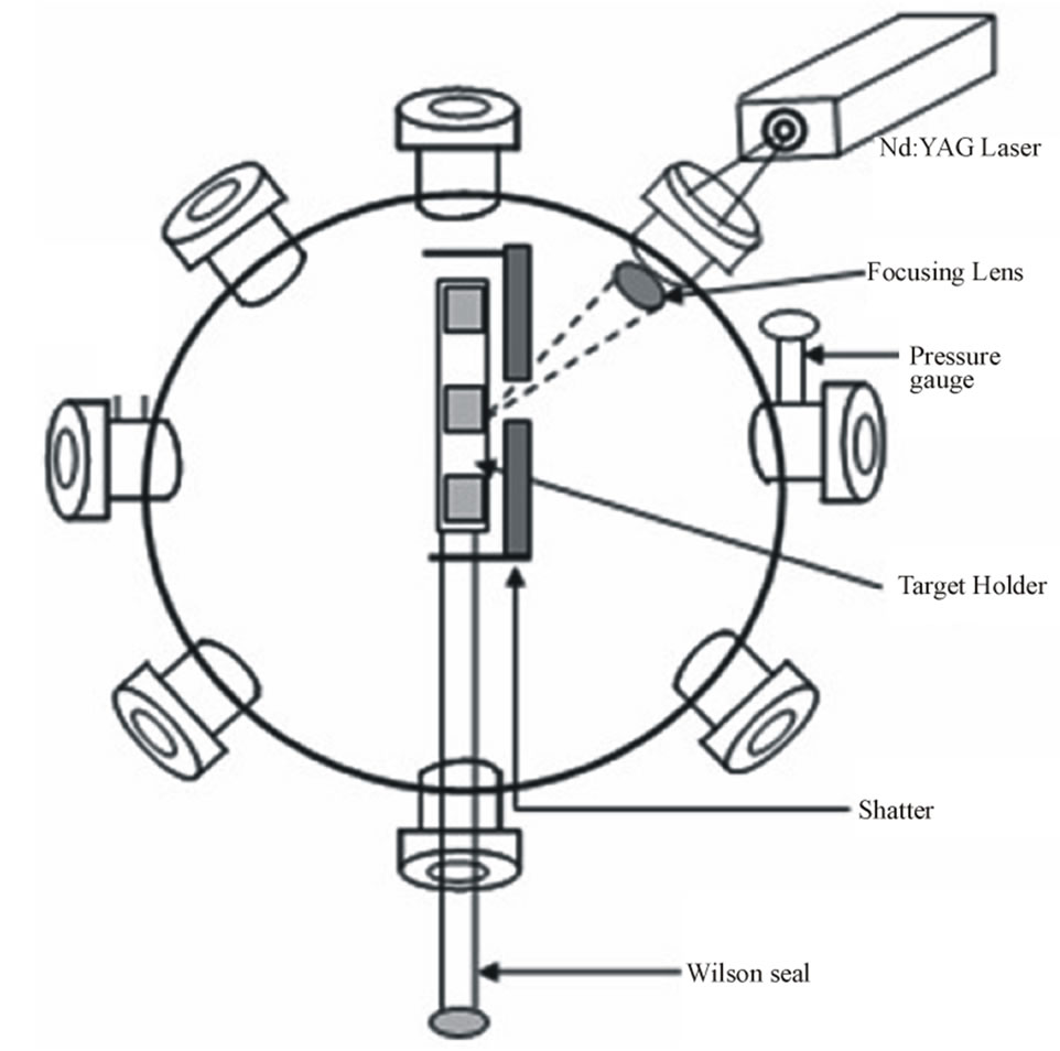
Figure 1. A Schematic of the Experimental set up.
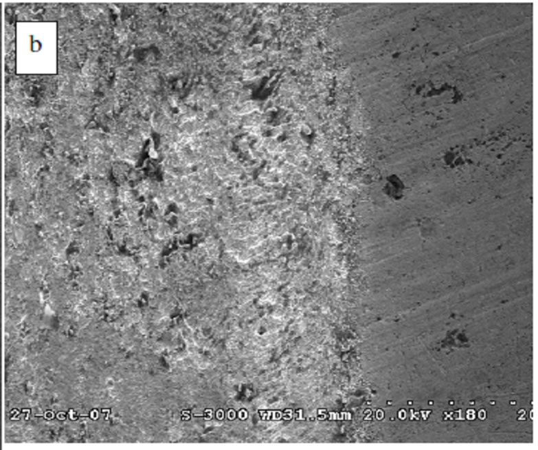
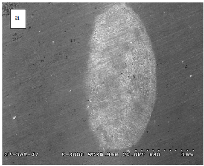
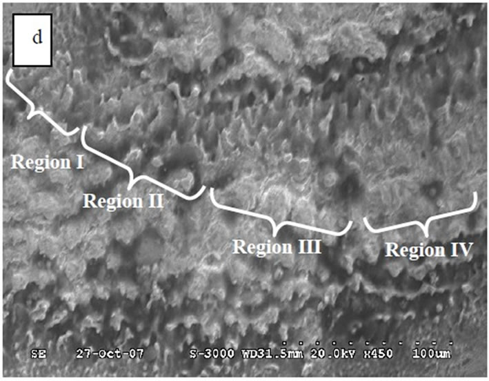

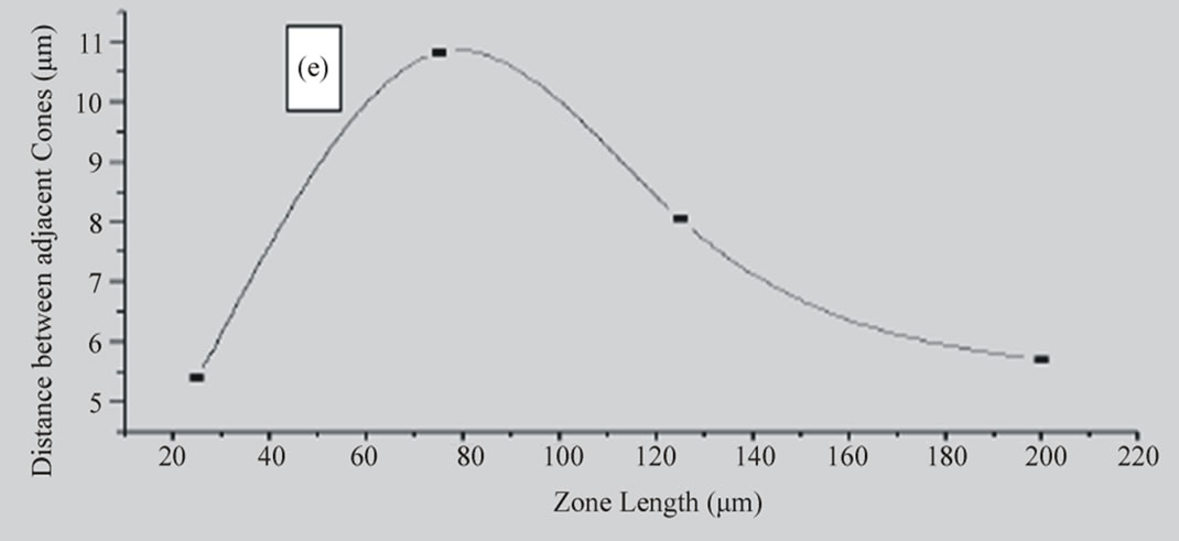
Figure 2. SEM Micrographs of platinum samples (a) (×30) irradiated in air for 50 shots. (b) (×180) irradiated in air for 50 shots. (c) (×450) irradiated in air for 50 shots. (d) (×450) irradiated under vacuum (~103torr) for 50 shots (e) Plot of average zone length (μm) versus the distance between adjacent cones (μm).
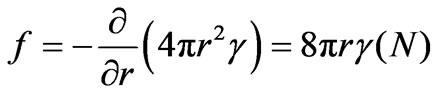
formation of wave patterns at the edges of the damaged site, due to continuous flow towards the boundary (Figure 2(b)). The formation of micron sized redeposited particles and cones like structures indicate ablation and exfoliation sputtering. Figure 2(c) indicates the disruption in morphology of the sample in the form of periodic surface structures due to attenuation and absorption of energy at the surface treated in air. This gives rise to splashing and hydrodynamic sputtering [9]. The average size of droplets calculated from the micrograph is 3.2 µm. The separation of asperities from the surface will be opposed by a force, acting as a restoring force, given by [4].
 (1)
(1)
where r is droplet radius and γ is the liquid surface energy. The value of γ for platinum is 1.8J/m2 [4].
 (2)
(2)
This force must be compensated by the laser energy in order to eject the material. It becomes difficult for droplets of large radii to leave the surface whereas small droplets easily overcome the force of the surface resulting in splashing or vaporization. The cooling of ejected material causes redeposition. Formation of the droplets is due to surface tension occurring during resoldification of molten globules [4].
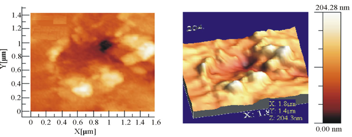
A crucial change in surface morphology occurs when sample is affected by laser irradiation under vacuum. Figure 2(d) shows the hydrodynamic flow of droplets from irradiated area. Splashing and sputtering resulted from energy absorption by the target surface. This energy absorption is through the formation of different channels [9]. Peaks, valleys and cone formations revealed the energy conservation. Micron sized droplets are observed in the immediate proximity outside the splashed hydrodynamic zone. This explosive expel of material is due to subsurface boiling with high pressure that lead in cones formation by resolidification. The distance between these cones formed in a particular sequence depends upon the surface properties of melted region [4,17-18]. A plot of distance between adjacent cones and corresponding zone lengths measured from ablated region is shown in Figure 2(e). The average distance between the adjacent cones is comparatively large near the crater region. The distance between cones is dependent on the surface tension of the liquid in term of surface energy as those regions had minimum distance followed the larger melted area than others. As material tends to splashed out, it gets less possibility to be ejected due to more surface energy. So a crater is formed due to washing out the molten in the region with large asperities distance. [4]. Topography in two dimensions of the irradiated area and the corresponding surface profiles are shown in Figures 3(a) and (b) and Figures 4(a) and (b) respectively Surface texture and morphology clearly indicates hillocks, valleys and crater formation (Figures 5(a) and (b)). The measured size for the hillock is 559 nm with maximum height of
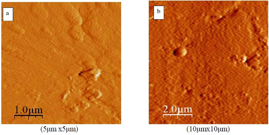
Figure 3. Two dimensional AFM images (a) irradiated platinum (b) droplets and melted materials on platinum surface.
 (a)
(a)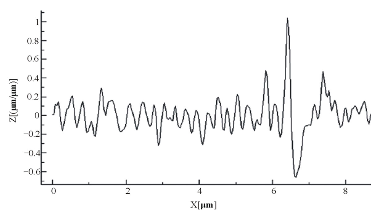 (b)
(b)
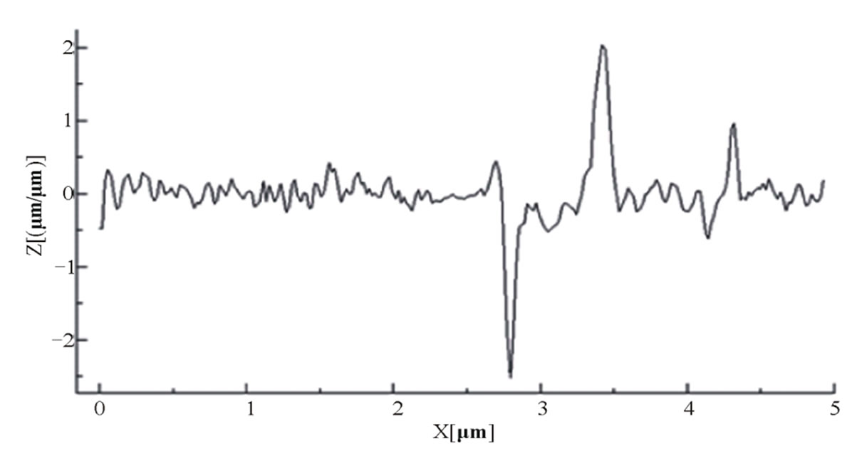
Figure 4. Surface profile (a) irradiated target in air (b) irradiated target under vacuum (10–3 torr).
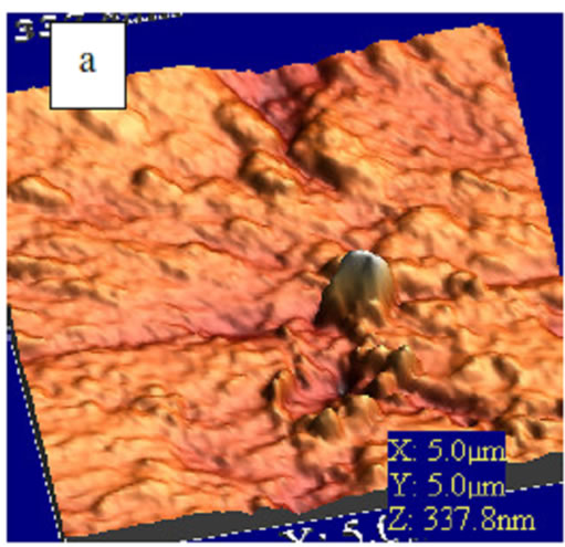
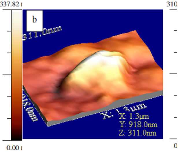
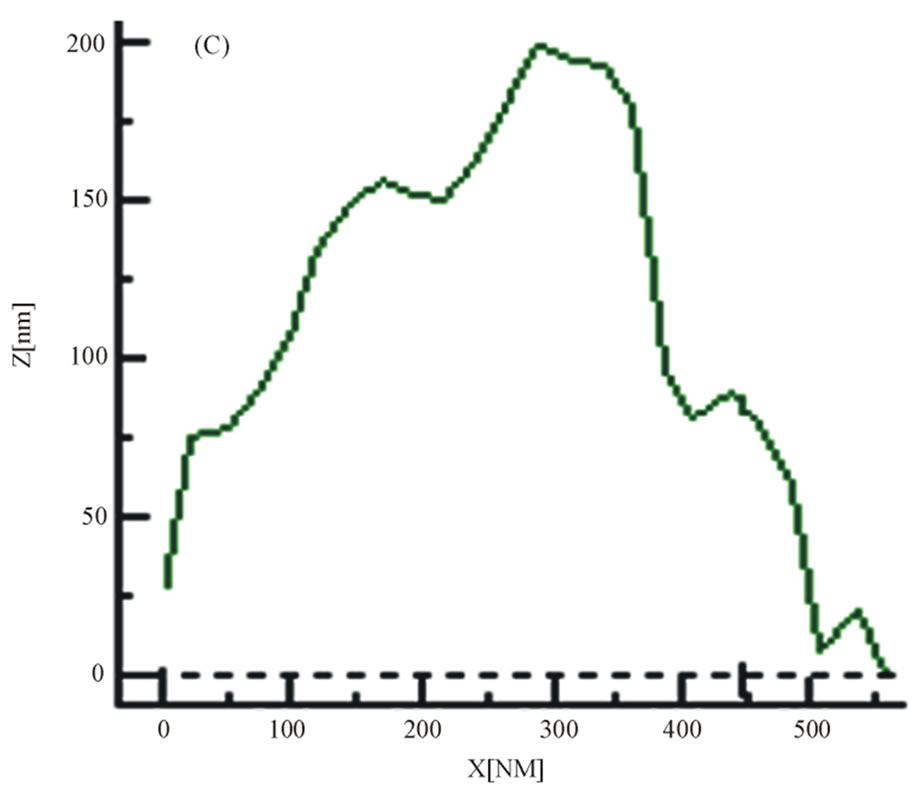
Figure 5. (a) Hillock formation on the target surface irradiated in air (1 atm) (b) Hillock focused area, appear as a heap of material undetached. (c) Measurement of a Hillock size (width 559 nm and height 288 nm).
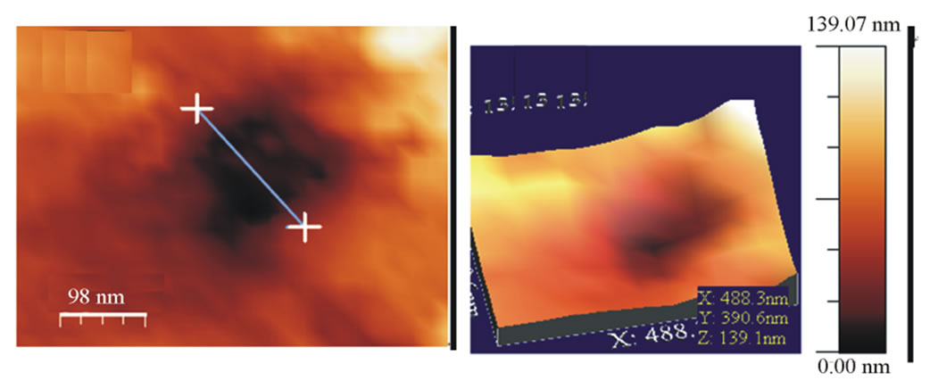
188 nm. Here the involved processes are thermal in nature as the undetached material appearing on the surface as a hill when the material is thermalized before the removal of material starts from a super heated liquid[19]. The electron-phonon and phonon-phonon interaction times may be less than time of thermalisation [20]. The images appearing in Figures 6(a) and (b) is a valley, a crater surrounded by various hills, appears to be the region splashed out of the crater on laser impact showing maximum absorption by the surface at atmospheric pressure. Size of the valley is 1.50 μm. IR radiation effects resulted in a crater of size 180.50 nm and depth of 40 nm. The rms roughness of the surface was found to be 23.91 μm (Figure 7).
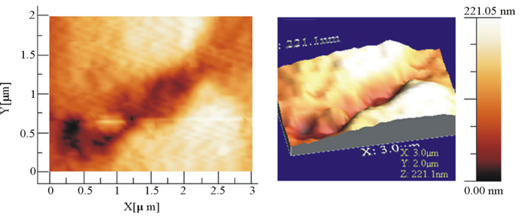
The track formation on the target surface under vacuum (~10–3 torr) is shown in Figures 8(a) and (b) respectively. The crater profile shows a depth of 50nm which is greater than that in air indicating more absorption of energy under vacuum. Figures 9(a) and (b) illustrate the resolidification of the material in the form of flakes. The marked particulate has a diameter of 0.90 μm. The surface topography indicates the rms roughness 67 μm which is greater as compared to that in air.
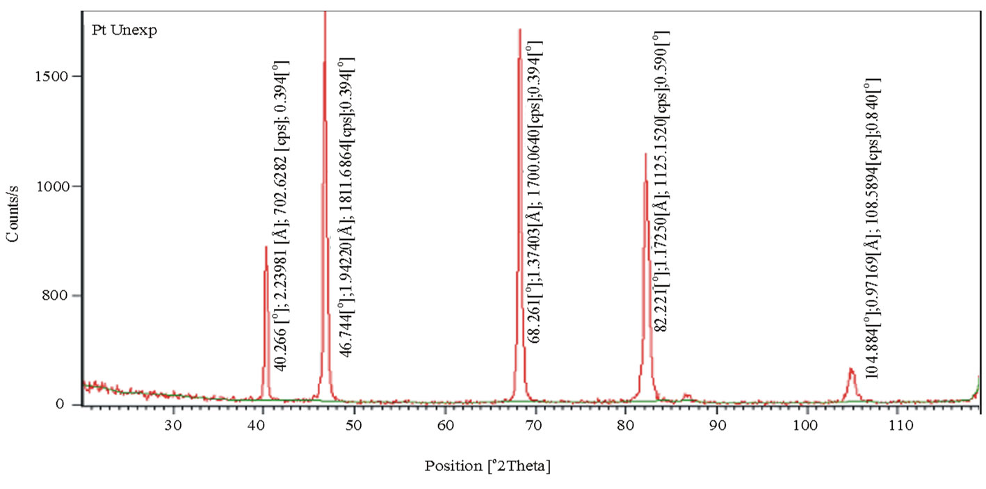
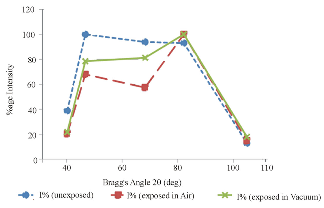
The structural changes in the irradiated samples were noticed through XRD patterns shown in Figures 10(a) -(c). An X-Ray diffraction pattern exhibits significant changes in intensities after the laser produced excitations. This behavior of sample confirms the strong threedimensional structural reorganization in photo-induced state, and also in good agreement to the good reproducibility of the previous results for other metals [21-23]. The comparative study of unexposed and exposed platinum samples, both in air and under vacuum, indicate that the peak intensity values are varying. Grains unstrained positions due to laser heating, recrystalisation at elevated temperature, defects and imperfections within the crystal may cause intensity variation [6-7,22,24,25]. The variation in intensity is demonstrated by a sharp decrease for the exposed sample in air (Figure 11(a)) at Bragg’s angle 2q = 70˚. Monotonic decrease in grain size is also
 (a) (b)
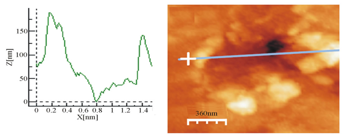 (c) (d)
Figure 6. AFM micrographs (a) indicating crater formation due to laser irradiation (b) showing a valley, craters surrounded by various hills on the target surface (c) Surface profile of the formed valley (d) Average size measurement of the valley (1.50 μm).
 (a) (b)
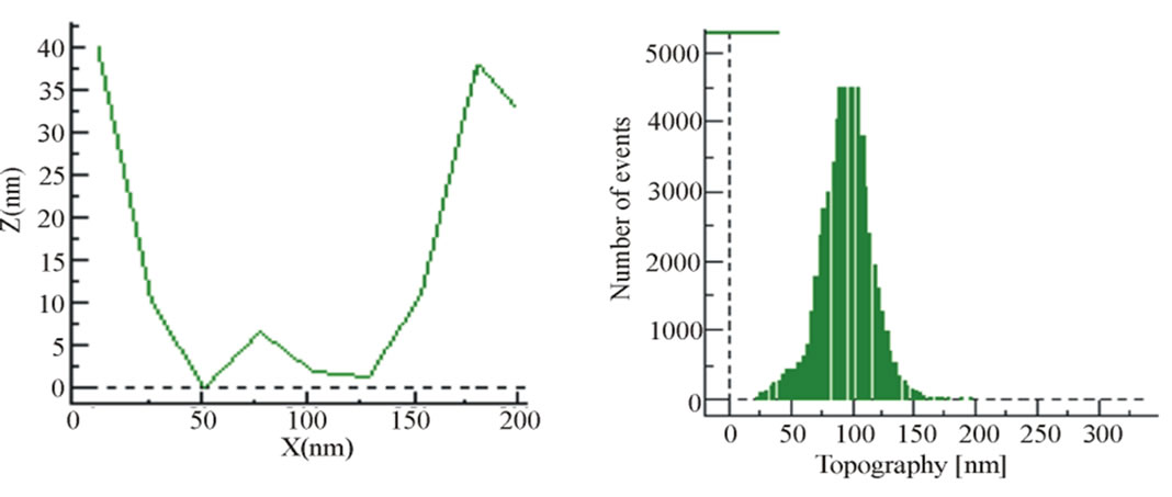 (c) (d)
Figure 7. (a) AFM micrograph, crater formation measurement (b) Crater appearing as a part on the Surface (c) Crater size and depth (Size = 180.50 nm, Depth = 40nm) (d) Surface roughness measurement by topographic histogram (rms roughness = 23.91 mm).
 (a) (b)
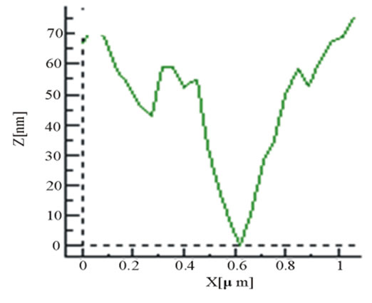 (c) (d)
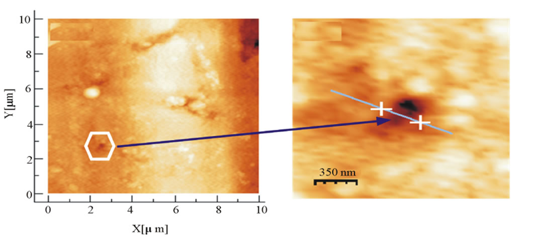 (e)
(e)
Figure 8. (a) AFM Micrograph, Laser Impact Effects on the Surface under vacuum (10–3 torr) (b) Track Profile on the Surface due to Laser Impact (c) Crater Formation (d) Crater Size Measurement on the Surface (e) Surface Profile for the Measurement of Crater Depth (50 nm).
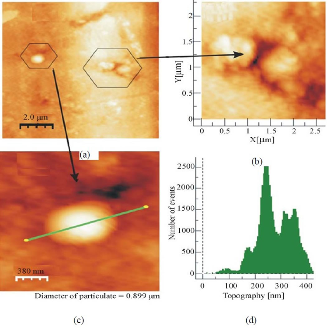
Figure 9. AFM micrographs (a) indicating resolidified Material (b) Droplet formations indicating splashing (c) Size measurement of the marked drop (0.90 μm) (d) RMS roughness of the surface (67 μm).
 (a)
(a)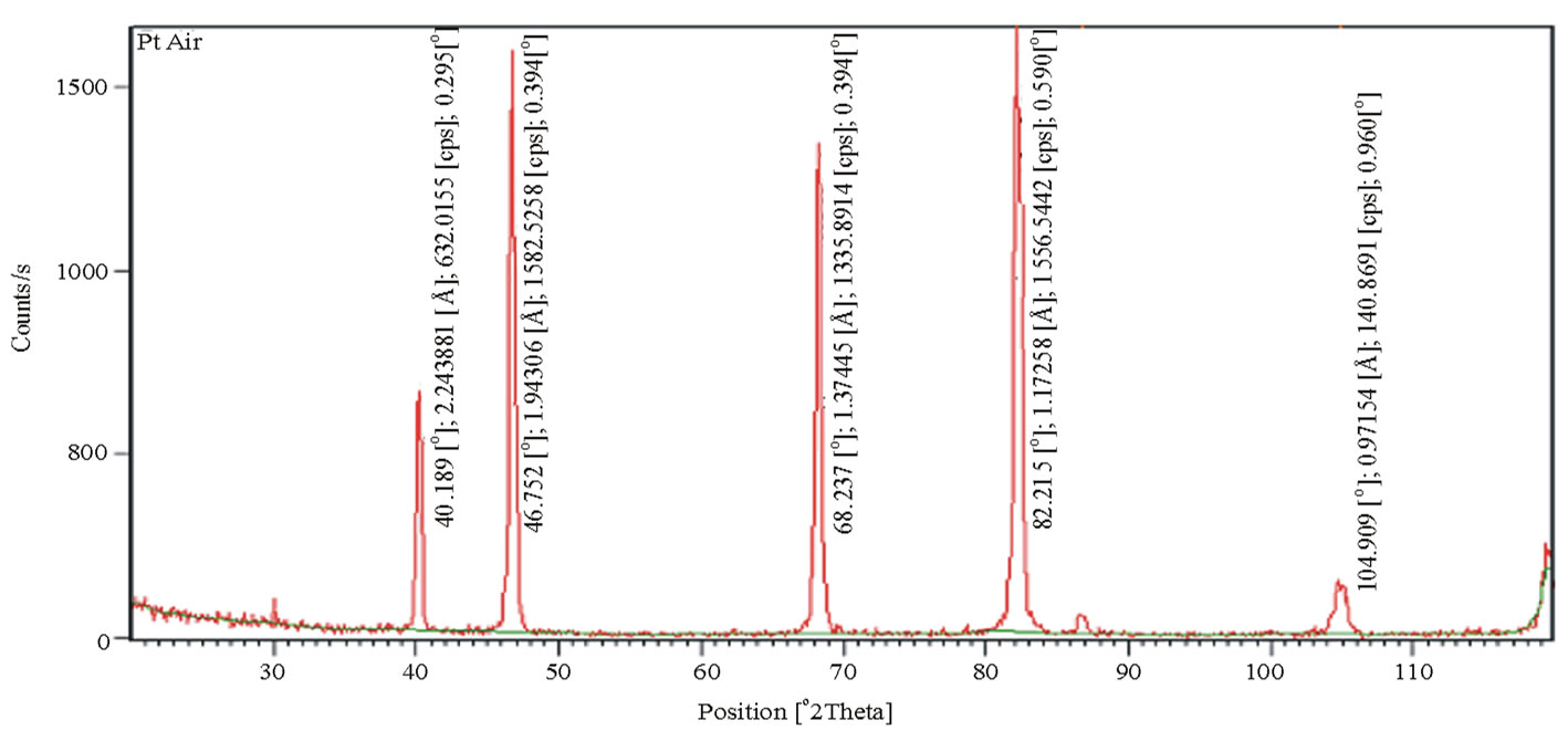 (b)
(b)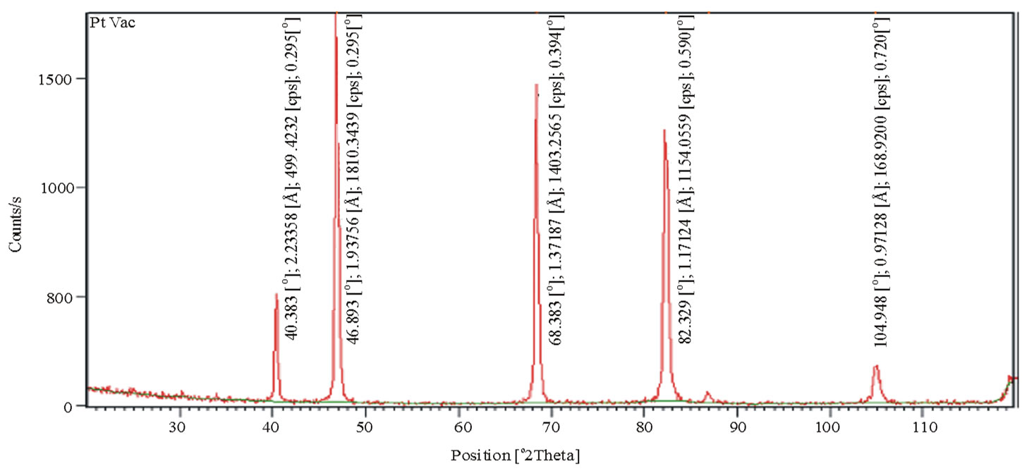 (c)
(c)
Figure 10. XRD patterns (a) unexposed platinum sample in air (b) irradiated platinum sample in air (c) irradiated of platinum sample (pressure 10–3 torr).
 (a)
(a)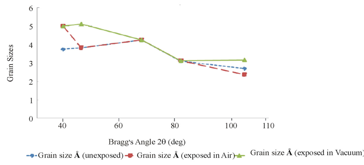 (b)
(b)
Figure 11. The plots of (a) diffracted X-ray intensity vs. Bragg’s angle 2q (b) Grain sizes vs. Bragg’s angle 2q.
observed with the Bragg’s angle (Figure 11 (b)). Irradiation does not impose any significant change in d-spacing of the target planes. Variations in FWHM of the peaks resulted in small modifications in grain sizes. The results obtained are in agreement with those obtained by other experimentalists investigating laser-matter interaction on such other metals [6-12, 26,27].
4. Conclusions
Non-uniform heat conduction occurs in laser platinum interaction. Material ejection occurs with explosive expel under vacuum than as compared with that in air. Thermal splashing, sputtering phenomena and hydrodynamic flow are pretty clear. Distance between consecutive asperities/cones is larger near the crater and it goes on decreasing with the distance from crater. The surface roughness and crater depth are more for samples irradiated under vacuum. No significant change is imposed by radiations on d-spacing of the target material. Large variations take place in the intensity of diffracted x-rays whereas FWHM and grain sizes vary slightly.
5. Acknowledgments
The authors acknowledge “Centre of Excellence in solid state Physics, Punjab University, Lahore, Pakistan” for providing AFM facility.
REFERENCES
- P. Lorazo, L. J. Lewis and M. Meunier, “Thermodynamic Pathways to Melting, Ablation and Solidification in Absorbing Solids under Pulsed Laser Irradiation,” Physical Review B, Vol. 73, No. 13, 2006, p. 134108. doi:10.1103/PhysRevB.73.134108
- J. C. Miller and R. F. Haglund, “Laser Ablation and Desorption,” Academic Press, Waltham, 1998.
- S. R. Franklin and R. K. Thareja, “The Effects of Degraded Spatial Coherence on Ultra–Fast Laser Channel Etching” Appied Surface Science, Vol. 222, No. 1-4, 2004, pp. 293-306. doi:10.1016/j.apsusc.2003.08.083
- D. B. Chrisey and G. K. Hubler, “Pulsed Laser Deposition”, John Willey and Sons, New York, 1994.
- D. Perez and L. J. Lewis, “Damage in Materials Following Ablation by Ultrashort Laser Pulses: A Molecular-Dynamics Study,” Physical Review Letter, Vol. 89, No. 25, 2002, p. 255504. doi:10.1103/PhysRevLett.89.255504
- M. Khaleeq-ur-Rahman, K. A. Bhatti, M. S. Rafique, A. Latif, et al., “X-rays Emission from Laser Induced Copper Plasma under External Magnetic Field,” Laser Physics, Vol. 17, 2007, p. 1382.
- M. S. Rafique, M. Khaleeq-ur-Rahman, T. Firdos, K. A. Bhatti, M. Imran and H. Latif. “Plume Dynamics and Radiation Emission from Laser Plasmas,” Laser Physics, Vol. 17, No. 9, 2007, p. 1138. doi:10.1134/S1054660X0709006X
- C. R. Philips, “Laser Ablation and Applications,” Springer Series in Optical Sciences, Vol. 29, 2007, p. 588.
- A. Latif, M. Khaleeq-ur-Rahman and M. S. Rafique, Proceeding “Laser Ablation Phenomena in Metals,” Conference on Advanced Materials, Putrajaya, Malaysia, 2005, p. 154.
- P. Gibbon, “Short Pulse Laser Interaction with Matter: An Introduction,” Imperial College Press, London, 2005.
- V. S. Burakov, A. F. Bokhonov, Nedel’ Ko and N.V Tarasenko, “Change in the Ionisation State of a NearSurface Laser-Produced Aluminium Plasma in Double-Pulse Ablation Modes,” Applied Surface Science, Vols. 138- 139, 1999, p. 350. doi:10.1016/S0169-4332(98)00575-3
- B. N. Chichkov, C. Momma, S. Nolti, F. Von Alvensleben and A. Tunnerman, “Laser Beat Wave Excitation of Surface Plasma Wave and Material Ablation,” Applied Physics A, Vol. 63, No. 2, 1996, pp. 109-115. doi:10.1007/BF01567637
- M. Khaleeq-ur-Rahman, A. Latif, A. Hayat, M. S. Rafique, A. Usman and A. Rehman, “ Surface Modifications of Materials by Repititive Laser Pulses,” Radiation Effects and Defects in Solids, 2011 (accepted).
- H. G. Rubahn, “Laser Applications in Surface Science and Technology,” John Wiley and Sons, New York, 1999.
- J. W. Elan and D. H. Levy,” Low Fluence Laser Sputtering of Gold at 532nm,” Journal of Applied Physics, Vol. 81, No. 1, 1997, p. 539-542. doi:10.1063/1.364095
- A. Pereira, P. Delaporte, M. Sentis and W. Marine, “Optical and Morphological Investigation of Backward-Deposited Layer Induced by Laser Ablation of Steel in Ambient Air,” Applied Physics, Vol. 98, 2005, p. 8.
- J. Maul, I. Strachnov, S. Karpuk, P. Bernhard, A. Oelsner, G. Schonhense and G. Huber, “Onset of Crater Formation during Short Pulse Laser Ablation,” Applied Physics A, Vol. 82, No. 1, 2006, pp. 43-47. doi:10.1007/s00339-005-3357-3
- J. M. Fishburn, M. J. Withford, J. A. Coutts, et al., “Study of the Interplay of Vaporization, Melt Displacement and Melt Ejection Mechanisms under Multiple Pulse Irradiation of Metals,” Applied Surface Science, Vol. 253, No. 2, 2006, pp. 662-667. doi:10.1016/j.apsusc.2005.12.168
- Matsunami, O. Fukuoka, M. Tazawa and M. Sataka, “Composition and Optical Properties of Silicon Nitride Films Grown on SiO2-Glass and R-Al2O3 Substrates by Reactive RF Magnetron Sputtering,” Surface Coating Technology, Vol. 196, No. 1-3, 2005, pp. 50-55. doi:10.1016/j.surfcoat.2004.08.093
- H. Latif, M.S. Rafiqe, M. Khaleq-ur-Rahman, R. S. Rawat, A. Sattar, S. Naseem and P. Lee, “Impact of Laser Produced X-Rays on the Surface of Gold,” Applied Surface Science, Vol. 254, No. 22, 2008, p. 7505-7511. doi:10.1016/j.apsusc.2008.06.032
- A. Arbonet, “Electron-Phonon Scattering in Metal Clusters,” Physical Review Letter, Vol. 90, No. 17. 2003, pp. 177401-177405. doi:10.1103/PhysRevLett.90.177401
- W. F. Smith, “Principles of Material Science and Engineering,” McGraw-Hill, Tokyo, 1990.
- B. D. Culity, “Elements of X-Ray Diffraction,” Edison Wesley, London, 1978.
- R. Jordan, D. Cole, J. G. Lunney, K. Mackay and D. Givord, “Pulsed Laser Ablation of Copper,” Applied Surface Science, Vol. 86, No. 1-4, 1995, pp. 24-28. doi:10.1016/0169-4332(94)00370-X
- E. Mirica, G. Kowach, P. Evans and H. Du, “Morphological Evolution of ZnO Thin Films Deposited by Reactive Sputtering,” Crystal Growth Design, Vol. 4, No. 1, 2004, pp. 147-156. doi:10.1021/cg025595j
- N. Bidin, R. Qindeel, M. Y. Daud and K. A. Bhatti, “X-Rays Emission from Laser Induced Copper Plasma under External Magnetic Field,” Laser Physics, Vol. 17, No. 10, 2007, pp. 1222-1228. doi:10.1134/S1054660X07100064
- A. Latif, M. Khaleeq-ur-Rahman, K. A. Bhatti, M. S. Rafique and M. Imran, “Irradiation Effects on Copper”, Radiations Effects and Defects in Solids, Vol. 164, No. 1, 2009, pp. 68-72. doi:10.1080/10420150802163950