Open Journal of Fluid Dynamics
Vol.3 No.2(2013), Article ID:33674,6 pages DOI:10.4236/ojfd.2013.32018
Effects of Hub Profiles on Efficiency and Flow of Jet Fan with Single Stage Impeller
Faculty of Engineering, Kyushu Institute of Technology, Kitakyushu, Japan
Email: turbo@tobata.isc.kyutech.ac.jp
Copyright © 2013 Shinpei Kametaka et al. This is an open access article distributed under the Creative Commons Attribution License, which permits unrestricted use, distribution, and reproduction in any medium, provided the original work is properly cited.
Received January 14, 2013; revised February 15, 2013; accepted February 22, 2013
Keywords: Jet Fan; Bidirectional Flow; Impeller; Initial Cost; Performance
ABSTRACT
The traditional jet fans have equipped with the tandem impellers and the exclusive motors, and such designs are associated with the expensive initial cost. This serial research proposes how to simplify the fan profile for reducing the initial cost without the performance deteriorations. The paper discusses the effects of the hub profiles installed in the traditional/commercial jet fan, on the performances in the several type single-stage work. The hub with the long tail corn gives the best efficiency, and not only the stay vanes but also the cooling fins deteriorate more or less the performances, accompanying the impeller works as follows. The efficiency at the reverse rotation of the original impeller, namely at the flow condition running from the outlet to the inlet, is doubtlessly lower than one at the original rotation. The unique cascade, where the leading and the trailing edges of the blade are alternated in the tangential direction, was prepared in anticipation of improving the performances. These results advise the desirable profile of the jet fan equipped with the single-stage impeller, and the numerical simulation provides the optimum blade profile for the bidirectional flow.
1. Introduction
The jet fan installed in the driveway tunnel is required to exhaust the injurious gasses in the bi-directions, namely the inlet and/or the outlet, at the emergency such as fires, traffic accidents and so on. Then, the traditional jet fan is generally equipped with the two-stage impellers which are effective to one direction, and each impeller is driven by the exclusive and particular motor. The impeller profiles have been optimized by many researchers and engineers [1-4], but above assemblages make not only the dimensions large but also the initial cost expensive.
To overcome such weak points, this serial research proposes how to simplify the jet fan profile for reducing the initial cost without the performance deteriorations as possible. This paper discusses the effect of the hub profiles, installed in the traditional/commercial jet fan, on the performances, while the several type impellers are in the single-stage work.
2. Model Jet Fan and Experiments
2.1. Model Jet Fan
Figure 1 shows the model jet fan where the length of the casing is 1.129 m, the duct diameter is 0.304 m with the hub ratio 0.41. The model jet fan was designed so as to meet the downsized dimensions of the standardized jet fan with the bore 1.025 m [5]. The motor is, however, set on the outside of the casing and drives the single impeller through the pulley system with the torque meter and the tachometer because the large sized motor was provided for the experiments. The rotational speed of the impeller was kept constant at 1700 min−1 by the inverter control. The flow is measured with the 3-holes pitot tube as the steady state conditions, at the Sections S1-S6 shown in Figure 1.
Three kinds of hub and stay vanes are prepared, the profiles and position of are shown in Figure 2, which have (a) the long tail corn with the half convergent angle 12 degrees (Long Tail Hub), (b) the short tail corn with the angle 24 degrees (Short Tail Hub) and (c) have not the tail corn (Suddenly Enlargement Hub). The cylindrical hub with the tail corn is supported by the three thin piano wires at two positions. Figure 3 shows the aircooling fin. The impeller and the stationary nose hub overhang the duct from the bearing box supported by the stay vanes at the inlet, while the nose hub profiles are the same as the tail hubs at the radius larger than the bearing box.
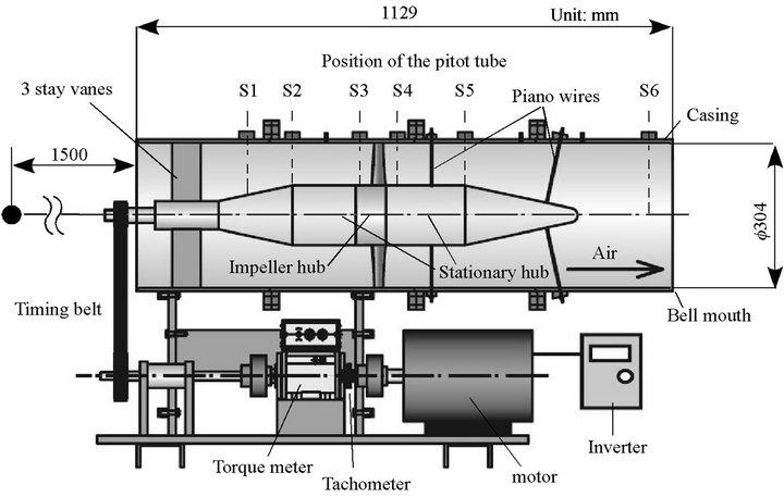
Figure 1. Model jet fan.
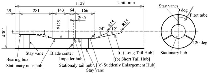
Figure 2. Model hub and model stay vanes.

Figure 3. Model air-cooling fin.
2.2. Impeller Profiles
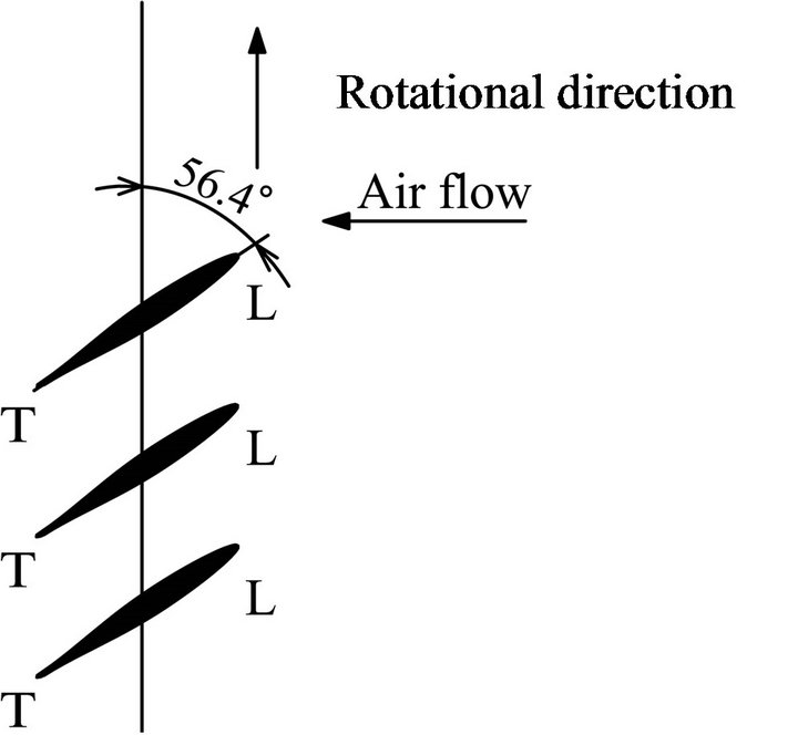
Figure 4 shows the original blade profile of the model impeller composed of 8 blades with the tip diameter 0.302 m, which is appropriated from the traditional/ commercial jet fan with the tandem impellers. The blade element has no camber but is twisted to make the swirling velocity component constant in the radial direction. Three kinds of the impellers/cascades were prepared in

Figure 4. Original blade profiles.
the experiments, as shown in Figure 5. These are called (a) “Original Type Impeller” taking Figure 4 as it is, (b) “Alternate Type Impeller” where the leading and the trailing edge positions of the original blade are alternated in the tangential direction, and (c) “Reverse Type Impeller” reversing Original Type Impeller. The blade setting angle were also adjusted between ±7 degrees from the normal dimensions given in Figures 4 and 5 (the adjusting angle is shown by Δβ and the positive value is
 (a)
(a) (b)
(b) (c)
(c)
Figure 5. Impeller profiles. (a) Original type impeller; (b) Alternate type impeller; (c) Reverse type impeller.
in the clockwise).
3. Effects of Impeller Profile
Figure 6 shows effects of the blade setting angle on the fan efficiency with Long Tail Hub, where η is the jet fan efficiency [=QΔPT/L, Q: the discharge, ΔPT: the difference of total pressure between Sections S1 and S6, L: the shaft power]. Original Type Impeller takes the maximum efficiency, and the efficiency of Alternate Type Impeller is between those of Original and Reverse Type Impellers. Besides, the impellers with the normal dimension, Δβ = 0 degree, have the maximum efficiency regardless of the impeller types.
To know the acoustic noise from the model jet fan, the microphone of the sound-level meter was set at 1.5 m front of the inlet on the centerline of the shaft as shown in Figure 1. The measured data was accumulated momentarily in the computer and the characteristics were processed by the FFT analyzer. The level and the frequency of the acoustic noise were evaluated without the background noises emitted from the motor, pulley system and the ambient circumstances. To normalize these noises, the specific sound level LSA [=SPL – 10log  + 20] is shown in Figure 7. The increase of the blade adjusting angle, namely the impeller giving the higher head and/or discharge, has the acceptable effect to suppress comparatively the noise. Reverse Type Impeller generates the higher noise than the other type impellers, because not only the cusp leading edge causes the stall on the large scale but also the blunt trailing edge brings markedly the velocity defect. Alternate Type Impeller can reduce the effects of the stall at the leading edge and the wake flow from the trailing edge, but the noise is unfortunately larger than Original Type Impeller, as it is.
Figure 8 shows the effects of the hub profiles on the jet fan efficiency η at Δβ = 0. The efficiency is better with the moderate increase of the tail corn length. It can hardly ask the suddenly enlargement hub to take the high efficiency.
Figure 9 shows the specific sound level LSA derived from Figure 8. The level seems to be in counter propor-
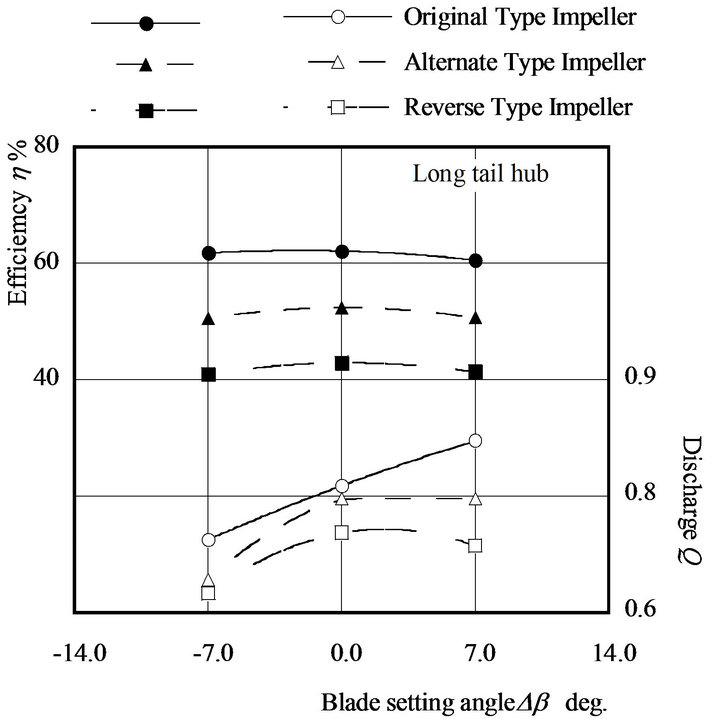
Figure 6. Effect of the impeller profiles on the jet fan efficiency and discharge.
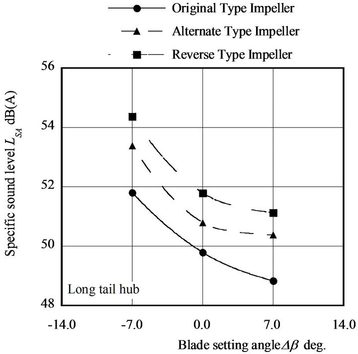
Figure 7. Effect of the impeller profiles on the specific sound level.
tion to the efficiency in Figure 8, as the flow separation increases the mixing losses in the downstream passage

Figure 8. Effect of the hub profiles on the fan efficiency.
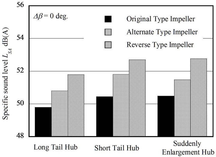
Figure 9. Effect of the hub profiles on the specific.
and promotes the noise.
4. Effects of Air-Cooling Fan and Vanes
The air-cooling fin may work partly to turn the flow near the hub wall to the axial direction as if the guide vane, but such an effect is tiny. Table 1" target="_self"> Table 1 shows the effects of the air-cooling fin on the jet fan efficiency η and the specific sound level LSA at Δβ = 0. The fin scarcely deteriorates the efficiency but makes the specific sound level increase more or less.
The effects of the stay vanes as shown in Figure 2, which are the flat plates with rounded leading and trailing edges, on h and LSA are shown in Table 2 while Δβ = 0 with Long Tail Hub. The stay vane causes the separation on the large scale at the leading edge and disturbs the flow discharged from the impeller. Then, it is desirable to equip with the cambered vanes or the slender bodies like circular cylinders in place of the flat plates.
5. Modification of Blade Profile
5.1. Numerical Simulation
The blade profile was modified on trial with the numeri-
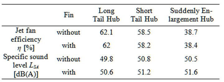
Table 1. Effect of the air-cooling fin on jet fan performances.
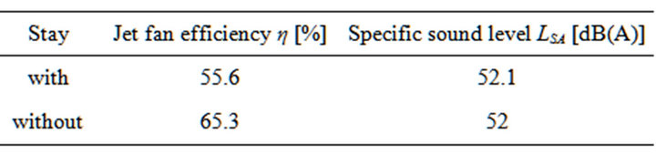
Table 2. Effect of the stay vane on jet fan performances.
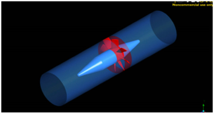
cal simulations by the commercial CFD code of ANSYS-CFX ver.12 with SST turbulent model, to provide the single stage impeller for the bidirectional type jet fan. The domain of the simulation is shown in Figure 10. The domain was divided into the rotational domain with the impeller, upstream and downstream stationary domains. The number of grid is about 800,000 for the rotating domain and about 800,000 for the stationary domains. These domains were connected with the frozen-rotor interface, while the boundary conditions are at the inlet and the constant static pressure at the outlet.
5.2. Flow Conditions around Original Impeller
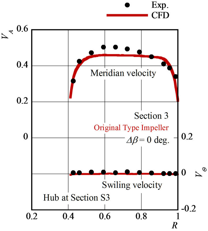
Figure 11 shows the axial VA and the swirling velocities VQ at Sections S3 and S4, where the velocities are divided by the impeller tip speed uT, R is the dimensionless radius with Long Tail Hub divided by the duct diameter. The commercial CFD code may simulate the flow around the impeller. Table 3" target="_self"> Table 3 shows the fan efficiency h and the average axial flow velocity VAM (divided by uT) at Section S6. The predicted results are in agreement with the experimental results.
5.3. Blade Profile Suitable for Bi-directions
The blade suitable for the bi-direction was designed to get the axial velocity VAM as the same as VAM of Original Type Impeller at the same rotational speed, with the aid of the numerical simulation whose reliability was verified above, and shown in Figure 12 (call Modified Impeller). The blade has no camber and the same profile at the leading and the tailing edges. Figure 13 shows the partial head H in the radial direction in comparison with H of Original Type Impeller, where Hth is the theoretical head averaged in the cross section of Original Type Impeller. The blade twists to increase the head in nearly proportion to the radius, though Original Type Impeller works mainly at the larger radius. Figures 14 and 15
 (a)
(a) (b)
(b)
Figure 10. Domains of numerical simulation. (a) Single impeller; (b) Tandem impeller.
 (a)
(a) (b)
(b)
Figure 11. Flow conditions. (a) Velocity distribution at Section S3; (b) Velocity distribution at Section S4.
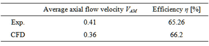
Table 3. Efficiency and average axial flow velocity at Section S6.
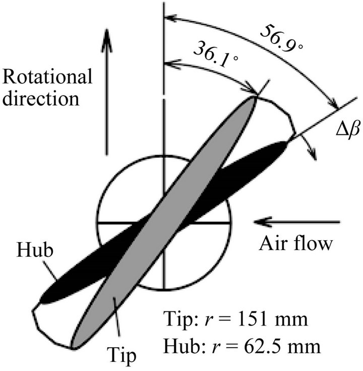
Figure 12. Optimized blade profile suitable for the bidirectional flows.
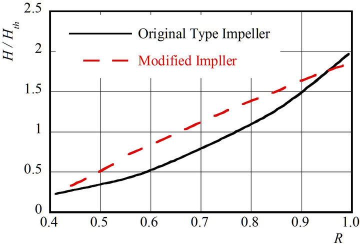
Figure 13. Partial head in the radial direction.
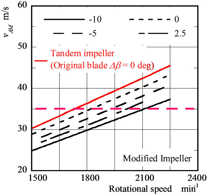
Figure 14. Effect of the blade profiles on the average axial velocity VAM.
show the effects of the blade adjusting angle Δβ on the average axial velocity VAM and the fan efficiency η, in comparison with the values of the tandem impellers with Original Type Impeller (the bidirectional jet fan, call
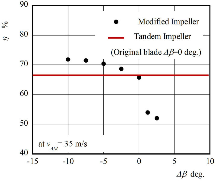
Figure 15. Effect of the blade profiles on the efficiency.
Tandem Impeller). Tandem Impeller takes the maximum velocity VAM regardless of the rotational speed. As for Modified Impeller, the normal adjusting angle, Δβ = 0, gives the higher velocity with the higher efficiency h as compared with one of Tandem Impeller. Modified Impeller with Δβ = 0 satisfies the rated velocity, VAM = 35 m/s, at the rotational speed n = 1816 min−1.
6. Concluding Remarks
To simplify the jet fan profile for reducing the initial cost without the performance deteriorations, the effects of the hub profiles on the performances and the flow conditions were investigated experimentally and numerically, using three type impellers/cascades. The efficiency at the reverse rotation of the original impeller, namely at the flow condition running from the outlet to the inlet, is doubtlessly lower than one at the original rotation. The unique cascade, where the leading and the trailing edges of the blade are alternated in the tangential direction, was prepared in anticipation of improving the performances, and gives the expected results. The hub with the long tail corn takes the best efficiency, but the stay vanes deteriorate the efficiency due to the flow separation at the leading edge. On the contrary, the air-cooling fins scarcely affect the efficiency and the flow condition. Based on these discussions, the blade profile was modified so as to take the acceptable performances.
7. Acknowledgements
The authors wish to thank Mr. S. Harada graduated from Kyushu Institute of Technology for helping the experiments, Mr. H. Kawakami and Mr. Y. Mitsuzuka of Fuji Electric Systems Co. Ltd. for fruitful discussions about the prototypes. Some parts of this research were thankfully co-sponsored by the 29th Harada Memorial Foundation.
REFERENCES
- M. Nishi, K. Yoshida, K. Kojima and H. Ishii “Aerodynamic Performance of a 2-Stage Jet Fan (Usage of a Rotor with Symmetric Blades),” Journal of Society of Mechanical Engineers, No. 38, 2004, pp. 129-130.
- S, Oba, “Development of the High Velocity Jet Fan,” Dengyosya Technical Review, Vol. 31, No. 1, 2007, pp. 9-13.
- M. Johkoh, T, Nishioka and T. Kanno, “Development of High-Speed Low-Noise Jet Fan for Modern Tunnel Ventilation Systems,” Proceedings of 9th Asian International Conference on Fluid Machinery, Jeju, 16-19 October 2007, No. AICFM9-056.
- H, Hayashi, “Effects of Blade Geometry on Flow and Noise Characteristics of Jet Fan,”Proceedings of 9th Asian International Conference on Fluid Machinery, Jeju, 16-19 October 2007, No. AICFM9-143.
- K, Hayashi, Y. Niizeki and S. Itoh, “JF-1000 High-Velocity Jet Fan,” Toshiba Review, Vol. 61, No. 8, 2006, pp. 32-35.
- T, Kanemoto, “Discussion of Numerical Flow Simulation for Counter-Rotating Cascades,” Vol. 1, IFFM Publishers, Gdansk, 2001.