Paper Menu >>
Journal Menu >>
 Intelligent Information Management, 2010, 2, 95-103 doi:10.4236/iim.2010.22012 Published Online February 2010 (http://www.scirp.org/journal/iim) Copyright © 2010 SciRes IIM Probabilistic Verification over GF(2m) Using Mod2-OBDDs José Luis Imaña Department of Computer Architecture, Faculty of Physics, Complutense University, Madrid, Spain Email: jluimana@dacya.ucm.es Abstract Formal verification is fundamental in many phases of digital systems design. The most successful verifica- tion procedures employ Ordered Binary Decision Diagrams (OBDDs) as canonical representation for both Boolean circuit specifications and logic designs, but these methods require a large amount of memory and time. Due to these limitations, several models of Decision Diagrams have been studied and other verification techniques have been proposed. In this paper, we have used probabilistic verification with Galois (or finite) field GF(2m) modifying the CUDD package for the computation of signatures in classical OBDDs, and for the construction of Mod2-OBDDs (also known as -OBDDs). Mod2-OBDDs have been constructed with a two-level layer of -nodes using a positive Davio expansion (pDE) for a given variable. The sizes of the Mod2-OBDDs obtained with our method are lower than the Mod2-OBDDs sizes obtained with other similar methods. Keywords: Verification, Probabilistic, OBDD, Mod2-OBDD, Galois Field GF(2m) 1. Introduction One of the most important aspects during circuit design is the verification, i.e., checking for functional equiva- lence. The translation of a circuit design from a high- level specification to a physical implementation depends on the correct transformation of its description at higher levels of abstraction to equivalent descriptions at more detailed levels. At logic level, verification consists of checking the equivalence of a Boolean function specifi- cation and its logic implementation. Most of the current successful equivalence checkers use Binary Decision Diagrams (BDDs) [1,2] or their derivatives as a core of the equivalence deduction engine. OBDDs [3,4] are used as canonical representations for both Boolean circuit specifications and logic designs. While OBDD-based methods have been quite successful in verifying combi- national and sequential circuits, they have significant limitations. For many circuits, verification systems that represent functions as OBDDs require a large amount of memory and time, and for some circuits the resource requirements are unacceptably large. Furthermore, OBDD sizes are quite sensitive to the ordering of their Boolean variables [5,6]. Various techniques have been proposed to reduce the memory complexity of BDDs by exploiting the structural and functional similarities of the circuits [7–9]. Some alternative to BDD-based equivalence checkers use Boolean Satisfiability (SAT) [10,11] or SAT-like methods (ATPG [12], recursive learning [13]) as a principal engine. In spite of the considerable advances in the area, the growing complexity of the verification instances moti- vates exploring the alternative approaches. Verification performed using OBDDs can be considered as a Deter- ministic Verification, in which if the OBDDs of the func- tions are the same (isomorphic), then these functions are said to be equivalent [14]. Another method that can be considered in order to circumvent the above limitations is the Probabilistic Verification, based on the theory of Blum, Chandra and Wegman [15], in which numeric codes or signatures represent the functions to be verified. This method is based on algebraic transforms of Boolean functions, so that a function can be substituted by its al- gebraic representation. A signature representing the func- tion is then obtained assigning numeric codes (randomly selected from a finite field) to the variables in the alge- braic representation, and then evaluating the result. The comparison is then performed over signatures, not over This work was partially supported by the Spanish Government Research Grant TIN2008-00508.  J. L. IMAÑA 96 data structures representing the functions [16]. Signa- tures can be computed more efficiently than graph-based representations, consume less time and space, and dis- tinguish any pair of Boolean functions with a very high probability of success. By performing several such runs with different random input variable assignments, the resultant algebraic simulation has a probability of error in verification that decreases exponentially from an ini- tially small value [16]. The probabilistic approach pre- sents significant advantages over deterministic methods using OBDDs. In deterministic verification, OBDDs are canonical representations of functions to be verified, and provide a basis for efficient computation. In probabilistic verification, functions are represented by signatures, not by a large data structure. Graph-based data structures are used only in intermediate evaluation steps. Therefore, more general OBDD-based models have been studied which can be used as such intermediate data structures [17–20]. In this paper, we consider Mod2-OBDDs [21] (also known as -OBDDs) which are extensions of OBDDs. Mod2-OBDDs are non canonical representations of Boolean functions. For canonical representations as OBDDs, testing the equivalence of two OBDDs simply reduces to the comparison of their pointers. For non ca- nonical representations as Mod2-OBDDs, a deterministic equivalence test requires time cubic in the number of nodes [22], and thus, it seems not to be suitable for prac- tical purposes. In [21], a fast probabilistic equivalence test for Mod2-OBDDs that requires only a linear number of arithmetic operations is used. In this contribution, a very efficient OBDD package (CUDD package from Colorado University) has been modified in order to construct Mod2-OBDD representa- tions of Boolean functions given in multilevel BLIF, and probabilistic verification based on Galois field GF(2m) arithmetic for the equivalence test (signatures compari- son) has been used. The addition of two elements from a binary extension field GF(2m) is simply a bitwise XOR of their corresponding binary representations, the sub- traction is exactly the same as addition, and the complex- ity of the multiplication depends on the irreducible gen- erating polynomial or the basis selected to represent the field elements [23–25]. These properties justify the use of GF(2m) as finite field. Firstly, OBDDs with signatures have been constructed. The signature-inclusion is carried out by including a 32 bit signature field on each OBDD-node and computing the signature in the synthesis process. This signa- ture-OBDD obtained has the same number of nodes as the original OBDD, but with the signature computed for the Boolean function that it represents. Secondly, Mod2-OBDDs have been constructed by the inclusion of a two-level layer of -nodes. This layer is created–using the positive Davio expansion (pDE) for a selected vari- able–in the synthesis of the BLIF file for the function. Signature is so computed for the Mod2-OBDD and is compared with signature obtained with the signa- ture-OBDD for the equivalence test. Times and sizes are compared for the three used structures (OBDDs, signa- ture-OBDDs and Mod2-OBDDs). The paper is structured as follows: In Section 2, some basic concepts concerning Mod2-OBDDs are introduced. In Section 3, probabilistic equivalence test using Galois field GF(2m) is presented. In Section 4, modifications on CUDD package for signature computation are outlined. Section 5 deals with the introduction of -nodes for the Mod2-OBDD construction. In Section 6, experimental results are presented. Finally, some conclusions are in- cluded in Section 7. 2. Mod2-OBDDs Mod2-OBDDs have been defined in [21]. A Mod2- OBDD (also known as -OBDDs) over a set Xn= {x1,x2,…,xn} of Boolean variables is a directed acyclic connected graph P where each node has out-degree 2 or 0. There is a distinguished non-terminal node, the root, which has in-degree 0. The two terminal nodes with out-degree 0, the 0-sink and the 1-sink, are labeled with the Boolean constants 0 and 1, respectively. The remain- ing non-terminal nodes v are either labeled with Boolean variables xiXn (denoted as branching or decision nodes), or with the binary Boolean operation XOR (-nodes). Let l(v) denote the label of the node v. The two edges starting in a non-sink node are labeled with 0 and 1. The 0-successor and 1-successor nodes of v are denoted by v0 and v1, respectively. If v2 is a successor of v1 in P and l(v1), l(v2)Xn then l(v1)<l(v2) according to a given or- dering on the set of input variables. The function fP associated with a Mod2-OBDD P is determined as follows. Given an input assignment a= (a1,a2,…,an){0,1} n, the Boolean values assigned to the leaves extend to Boolean values associated with all nodes of P as follows: If the successor nodes v0, v1 of a node v of P carry the Boolean values b0, b1, respectively, and if l(v)=xi, then v is associated with the value b0 or b1 according to xi =0 or xi=1. If l(v)=, then the value (b0,b1)=(b0 + b1) mod 2 is associated with v. The value fP(a) of the Boolean function fP represented by a Mod2-OBDD P is the value 1 or 0 associated with the root of P under the assignment a. A more compact representation can be obtained by using complemented edges [26]. 3. Probabilistic Verification Using Galois Fields Probabilistic verification consists of the generation of a Copyright © 2010 SciRes IIM  J. L. IMAÑA 97 code or signature for a Boolean function. The probabilis- tic comparison of two functions can be carried out by evaluating their representations on a randomly chosen vector of values selected from a finite field and compar- ing the results (signatures) obtained from the evaluation. If the signatures are different, then the functions are in- equivalent with certainty. If they are equal, then the functions are equivalent with a small probability of error. The signature for a Boolean function f(xn-1,…,x0) is generated by selecting random numerical values for each xi. These values can be selected from any field, but we will use the finite field GF(pm), with p prime and m N, representing a Galois field with pm elements. The evalua- tion of the function (with these randomly selected values assigned to its inputs) is carried out by the replacement of f(xn-1,…,x0) by an equivalent arithmetic function de- fined over the finite field. This replacement is deter- mined by an algebraic transformation of the Boolean function in terms of polynomials over the finite field. If we assign the polynomial px=x to a Boolean variable x, we can transform [16] the Boolean functions f and f1 f2 into the arithmetic expressions 1pf and pf1 pf2, re- spectively, where pf represents the polynomial assigned to the Boolean function f. By using the law of DeMorgan and idempotence, we can also transform f 1 f2 and f1f2 into pf1+pf2pf1 pf2 and pf1+pf22 pf1 pf2, respec- tively. It must be noted that the above arithmetic opera- tions are carried out on the selected finite field. In this paper, we consider the Galois field GF(2m) which is a characteristic 2 finite field with 2m elements, each of them represented as an m-bit vector. GF(2m) is an extension field of the ground field GF(2)={0,1}. The nonzero elements of GF(2m) are generated by a primitive element , where is a root of a primitive irreducible polynomial g(x)=xm +gm-1xm-1+…+g0 over GF(2). The nonzero elements of GF(2m) can be represented as the powers of , i.e., GF(2m)={0, 1, 2,…, , 22 m 21 m = 1}. Since is a root of g(x), g( )=0, and m=gm-1 m +…+g1 +g0. Therefore, an element of GF(2m) can also be expressed as a polynomial of with degree less than m, that is, GF(2m)={am-1 m-1 +…+ a1 + a0 | aiGF(2) for 0 i m-1}. Arithmetic in a field of characteristic 2 is essentially modulo arithmetic. Therefore, the addition of two polynomials becomes the bitwise XOR of the corresponding binary representations, and subtraction is the same as addition. Multiplication of two polynomials is the most important and one of the most complex and time-consuming operations. Complexity depends on many factors, such as the selection of the irreducible polynomial or the basis selected to represent the field elements: polynomial, dual or normal bases [25]. Be- cause of its characteristic 2, the product 2pf1pf2 in GF(2 m) is zero, and the above polynomial for the XOR is simpli- fied to the GF(2m) addition. Complement of a field ele- ment is simply the complementation of its least signifi- cant bit (in polynomial basis), and multiplication can be carried out in any of the representation bases. It must be noted that the multiplication operation in GF(2m) re- quires O(m) elementary operations [27]. When the signatures [H1] and [H2] of two functions f1 and f2 to be checked for equivalence are computed (using the above transformations, and evaluating them over the Galois field), then the signatures are compared: if [H1] [H2], then the functions are inequivalent with certainty; but if [H1] [H2], then the functions are equivalent, with small probability of error. The probability of error [16] is bounded by 1–e-n/p (where n is the number of variables and p is the cardinal- ity of the finite field) and if p>>n, then 1–e-n/pn/p. Therefore the error probability associated with the prob- abilistic equivalence check can be reduced by either in- creasing the size of the field, or by making multiple runs (using on each run an independent set of random as- signments and computing the signatures for the func- tions). If the signatures are different, we are sure that the two functions are not the same. If they are equal, we choose a new set of input assignments and reevaluate. The probability of erroneously deciding that the func- tions is equal decreases exponentially with the number of such runs. Applying these concepts, the probabilistic equivalence test of two functions represented by their Mod2-OBDDs is determined by the algebraic transformation of the Mod2-OBDDs in terms of polynomials over GF(2m). A polynomial pv: (GF(2m))nGF(2m) can be associated with each node v of the Mod2-OBDD as follows [28]: 10 11 001 0 01 011 0 () 01 0(1) ()(1)()() ()() () vn vnv nn vn vn p x,...,x ,vissink x px,...,xxpx,...,x, l vxX px ,...,xp x ,...,x,lv The polynomial associated with a Mod2-OBDD P is the polynomial associated with the root of P, so the equivalence test of two functions is the signature com- parison of their Mod2-OBDD roots polynomials evalu- ated at the randomly chosen set of input variables se- lected from GF(2m). Let Pf and Pg be two Mod2-OBDDs representing the Boolean functions f and g, and assume that a0,…,an-1 GF(2m) are generated independently and uniformly at random. For the Boolean signatures pf and pg computed for the Mod2-OBDDs Pf and Pg it holds [28] that pf(a0,…,an-1)=pg(a0,…,an-1), if f=g, and Prob (pf(a0,…,an-1) =pg(a0,…,an-1))<½, if fg. Therefore, if two given signa- tures pf(a0,…,an-1) and pg(a0,…,an-1) are equal, then the functions f and g are equal only with a certain probability. An estimation of the probability that the signatures for two nodes representing different Boolean functions in a Copyright © 2010 SciRes IIM 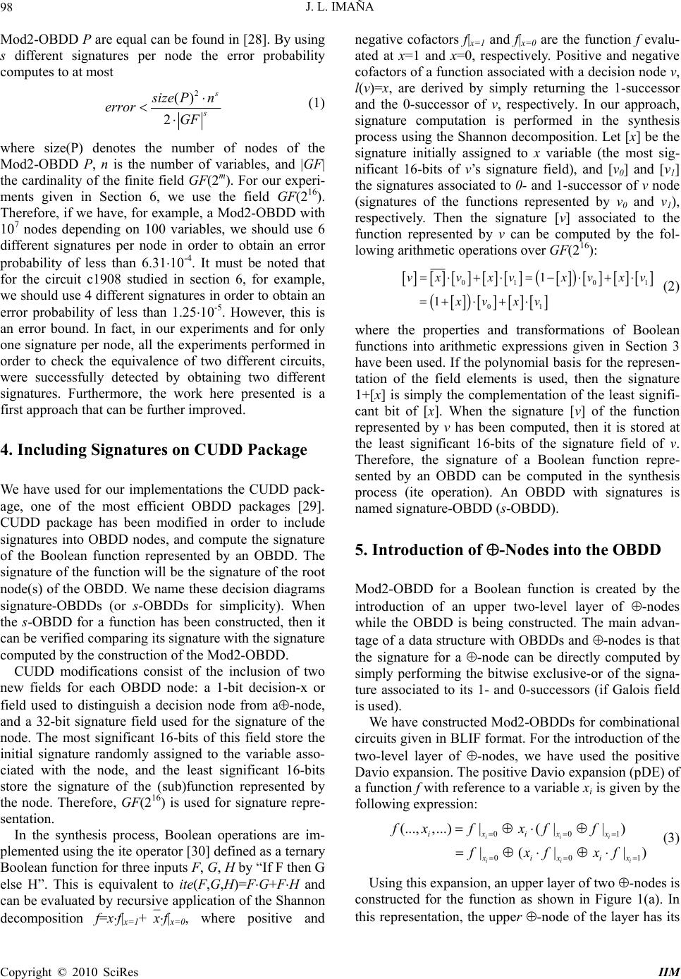 J. L. IMAÑA 98 Mod2-OBDD P are equal can be found in [28]. By using s different signatures per node the error probability computes to at most 2 () 2 s s s ize Pn error GF (1) where size(P) denotes the number of nodes of the Mod2-OBDD P, n is the number of variables, and |GF| the cardinality of the finite field GF(2m). For our experi- ments given in Section 6, we use the field GF(216). Therefore, if we have, for example, a Mod2-OBDD with 107 nodes depending on 100 variables, we should use 6 different signatures per node in order to obtain an error probability of less than 6.3110-4. It must be noted that for the circuit c1908 studied in section 6, for example, we should use 4 different signatures in order to obtain an error probability of less than 1.2510-5. However, this is an error bound. In fact, in our experiments and for only one signature per node, all the experiments performed in order to check the equivalence of two different circuits, were successfully detected by obtaining two different signatures. Furthermore, the work here presented is a first approach that can be further improved. 4. Including Signatures on CUDD Package We have used for our implementations the CUDD pack- age, one of the most efficient OBDD packages [29]. CUDD package has been modified in order to include signatures into OBDD nodes, and compute the signature of the Boolean function represented by an OBDD. The signature of the function will be the signature of the root node(s) of the OBDD. We name these decision diagrams signature-OBDDs (or s-OBDDs for simplicity). When the s-OBDD for a function has been constructed, then it can be verified comparing its signature with the signature computed by the construction of the Mod2-OBDD. CUDD modifications consist of the inclusion of two new fields for each OBDD node: a 1-bit decision-x or field used to distinguish a decision node from a-node, and a 32-bit signature field used for the signature of the node. The most significant 16-bits of this field store the initial signature randomly assigned to the variable asso- ciated with the node, and the least significant 16-bits store the signature of the (sub)function represented by the node. Therefore, GF(216) is used for signature repre- sentation. In the synthesis process, Boolean operations are im- plemented using the ite operator [30] defined as a ternary Boolean function for three inputs F, G, H by “If F then G else H”. This is equivalent to ite(F,G,H)=FG+FH and can be evaluated by recursive application of the Shannon decomposition f=xf|x=1+xf|x=0, where positive and negative cofactors f|x=1 and f|x=0 are the function f evalu- ated at x=1 and x=0, respectively. Positive and negative cofactors of a function associated with a decision node v, l(v)=x, are derived by simply returning the 1-successor and the 0-successor of v, respectively. In our approach, signature computation is performed in the synthesis process using the Shannon decomposition. Let [x] be the signature initially assigned to x variable (the most sig- nificant 16-bits of v’s signature field), and [v0] and [v1] the signatures associated to 0- and 1-successor of v node (signatures of the functions represented by v0 and v1), respectively. Then the signature [v] associated to the function represented by v can be computed by the fol- lowing arithmetic operations over GF(216): 01 0 01 1 1 vxvxv xvxv xv xv 1 (2) where the properties and transformations of Boolean functions into arithmetic expressions given in Section 3 have been used. If the polynomial basis for the represen- tation of the field elements is used, then the signature 1+[x] is simply the complementation of the least signifi- cant bit of [x]. When the signature [v] of the function represented by v has been computed, then it is stored at the least significant 16-bits of the signature field of v. Therefore, the signature of a Boolean function repre- sented by an OBDD can be computed in the synthesis process (ite operation). An OBDD with signatures is named signature-OBDD (s-OBDD). 5. Introduction of -Nodes into the OBDD Mod2-OBDD for a Boolean function is created by the introduction of an upper two-level layer of -nodes while the OBDD is being constructed. The main advan- tage of a data structure with OBDDs and -nodes is that the signature for a -node can be directly computed by simply performing the bitwise exclusive-or of the signa- ture associated to its 1- and 0-successors (if Galois field is used). We have constructed Mod2-OBDDs for combinational circuits given in BLIF format. For the introduction of the two-level layer of -nodes, we have used the positive Davio expansion. The positive Davio expansion (pDE) of a function f with reference to a variable xi is given by the following expression: 001 00 (..., ,...)|( ||) |(| | iii ii ixixx xixix fx fxff fxfxf 1 ) i (3) Using this expansion, an upper layer of two -nodes is constructed for the function as shown in Figure 1(a). In this representation, the upper -node of the layer has its Copyright © 2010 SciRes IIM 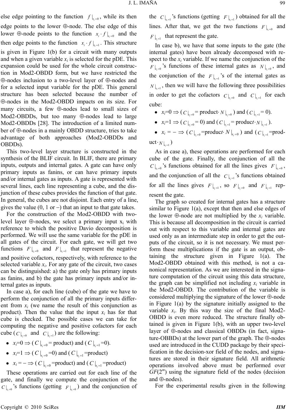 J. L. IMAÑA 99 else edge pointing to the function 0 i x f |, while its then edge points to the lower -node. The else edge of this lower -node points to the function 0 i ix x f| 1 i ix and the then edge points to the function x f| . This structure is given in Figure 1(b) for a circuit with many outputs and when a given variable xi is selected for the pDE. This expansion could be used for the whole circuit construc- tion in Mod2-OBDD form, but we have restricted the -nodes inclusion to a two-level layer of -nodes and for a selected input variable for the pDE. This general structure has been selected because the number of -nodes in the Mod2-OBDD impacts on its size. For many circuits, a few -nodes lead to small sizes of Mod2-OBDDs, but too many -nodes lead to large Mod2-OBDDs [28]. The introduction of a limited num- ber of -nodes in a mainly OBDD structure, tries to take advantage of both approaches (Mod2-OBDDs and OBDDs). This two-level layer structure is constructed in the synthesis of the BLIF circuit. In BLIF, there are primary inputs, outputs and internal gates. A gate can have only primary inputs as fanins, or can have primary inputs and/or internal gates as inputs. A gate is represented with several lines, each line representing a cube, and the dis- junction of these cubes provides the function of that gate. In general, the cubes are not disjoint. Each entry of a line, gives the value (0, 1 or ) that an input to that gate takes. For the construction of the Mod2-OBDD with two- level layer -nodes, we select a primary input xi with reference to which the positive Davio decomposition is performed. We will use the same variable for the pDE in all gates of the circuit. For each gate, we will get two functions and that represent the negative and positive cofactors, respectively, with reference to the selected variable xi. For any gate of the circuit, two cases can be distinguished: a) the gate only has primary inputs as fanins, and b) the gate has primary inputs and/or in- ternal gates as inputs. 0 i x F| 1 i x F| In case a), for each line (cube) of the gate we have to perform the conjunction of all the primary inputs differ- ent from xi (we name the result of this conjunction as product). Then the value that the input xi has for that cube is checked. The possible cases we can take for computing the negative and positive cofactors for each cube ( and ) are the following: 0 i x C| 1 i x C| xi=0 (0 i x C| = product) and (1 i x C| =0). xi=1 (0 i x C| =0) and (1 i x C| =product) xi = (0 i x C| =product) and (1 i x C| =product) These operations are carried out for each line of the gate, and finally we compute the conjunction of the ’s functions (getting 0 i x C| 0 i x F| ) and the conjunction of the 1 i x C| ’s functions (getting 1 i x F |) obtained for all the lines. After that, we get the two functions 0 i x F | and 1 i x F | that represent the gate. In case b), we have that some inputs to the gate (the internal gates) have been already decomposed with re- spect to the xi variable. If we name the conjunction of the 0 i x F | ’s functions of these internal gates as 0 i x N| , and the conjunction of the 1 i x F |’s of the internal gates as 1 i x N| , then we will have the following three possibilities in order to get the cofactors and 0 i x C| 1 i x C| for each cube: xi=0 (0 i x C| = product0 i x N| ) and (1 i x C| = 0). xi=1 (0 i x C| = 0) and (1 i x C| = product 1 i x N| ). xi = (0 i x C| =product0 i x N| ) and (1 i x C| =prod- uct 1 i x N| ) As in case a), these operations are performed for each cube of the gate. Finally, the conjunction of all the 0 i x C| ’s functions obtained for all the lines gives 0 i x F | , and the conjunction of all the 1’s functions obtained for all the lines gives 1, so0 i i x C| i x F| x F | and1 i x F | rep- resent the gate. The graph so created for internal gates has a structure similar to Figure 1(a), except that then and else edges of the lower -node are not multiplied by the xi variable. This is because all decomposition in the circuit is carried out with respect to this variable and internal gates are used only as an intermediate step in order to get the out- puts of the circuit, so it is not necessary. We must per- form these multiplications if the gate is an output, ob- taining the structure given in Figure 1(a). The Mod2-OBDD obtained with this method, is not a ca- nonical representation. As we are interested in the signa- ture computation of the circuit using this data structure, the graph can be simplified not including xi variable in the Mod2-OBDD. The contribution of the variable is considered multiplying the signature of the lower -node in Figure 1(a) by the signature initially assigned to the variable xi. By this way the size of the final Mod2- OBDD is even more reduced. The structure finally ob- tained is given in Figure 1(b), with an upper two-level layer of -nodes and classical OBDDs (in fact, signa- ture-OBBDs) at the lower part of the graph. The -nodes used are introduced in the CUDD package by their speci- fication in the decision-xor field of the nodes, and signa- tures are stored in their signature field. All arithmetic operations involved above must be performed over GF(2m) using the signature field of the nodes (decision and -nodes). For the experimental results given in the following Copyright © 2010 SciRes IIM 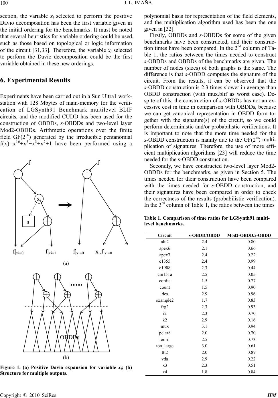 J. L. IMAÑA 100 section, the variable xi selected to perform the positive Davio decomposition has been the first variable given in the initial ordering for the benchmarks. It must be noted that several heuristics for variable ordering could be used, such as those based on topological or logic information of the circuit [31,33]. Therefore, the variable xi selected to perform the Davio decomposition could be the first variable obtained in these new orderings. 6. Experimental Results Experiments have been carried out in a Sun Ultra1 work- station with 128 Mbytes of main-memory for the verifi- cation of LGSynth91 Benchmark multilevel BLIF circuits, and the modified CUDD has been used for the construction of OBDDs, s-OBDDs and two-level layer Mod2-OBDDs. Arithmetic operations over the finite field GF(216) generated by the irreducible pentanomial f(x)=x16+x5+x3+x2+1 have been performed using a (a) (b) Figure 1. (a) Positive Davio expansion for variable xi; (b) Structure for multiple outputs. polynomial basis for representation of the field elements, and the multiplication algorithm used has been the one given in [32]. Firstly, OBDDs and s-OBDDs for some of the given benchmarks have been constructed, and their construc- tion times have been compared. In the 2nd column of Ta- ble 1, the ratios between the times needed to construct s-OBDDs and OBDDs of the benchmarks are given. The number of nodes (sizes) of both graphs is the same. The difference is that s-OBDD computes the signature of the circuit. From the results, it can be observed that the s-OBDD construction is 2.3 times slower in average than OBDD construction (with mux.blif as worst case). De- spite of this, the construction of s-OBDDs has not an ex- cessive cost in time in comparison with OBDDs, because we can get canonical representation in OBDD form to- gether with the signature(s) of the circuit, so we could perform deterministic and/or probabilistic verifications. It is important to note that the more time needed for the s-OBDD construction is mainly due to the GF(2m) multi- plication of signatures. Therefore, the use of more effi- cient multiplication algorithms [23] will reduce the time needed for the s-OBDD construction. f f Secondly, we have constructed two-level layer Mod2- OBDDs for the benchmarks, as given in Section 5. The times needed for their construction have been compared with the times needed for s-OBDD construction, and their signatures have been compared in order to check the correctness of the results (probabilistic verification). In the 3rd column of Table 1, the ratios between the times Table 1. Comparison of time ratios for LGSynth91 multi- level benchmarks. Circuit s-OBDD/OBDD Mod2-OBDD/s-OBDD alu2 2.4 0.80 apex6 2.1 0.66 apex7 2.4 0.22 c1355 2.4 0.99 c1908 2.3 0.44 cm151a 2.5 0.05 cordic 1.5 0.77 count 1.5 0.90 des 2.9 0.96 example2 1.7 0.83 frg2 2.3 0.93 i2 2.3 0.70 k2 2.9 0.16 mux 3.1 0.94 pcler8 2.0 0.70 term1 2.5 0.73 too_large 3.0 0.61 ttt2 2.0 0.87 vda 2.9 0.22 x3 2.3 0.51 x4 1.8 0.84 xi 0 f|xi=0 f|xi=1 f|xi=0 xi.f|xi=0 OBDDs Copyright © 2010 SciRes IIM  J. L. IMAÑA 101 Table 2. Sizes for OBDDs, two-level layer Mod2-OBDDs, and ratios between sizes of Mod2-OBDD and OBDDS. needed to construct two-level layer Mod2- OBDDs and s-OBDDs of the benchmarks are given. It can be ob- served that in all cases, Mod2-OBDD construction is faster than s-OBDD construction (0.66 times faster in average), even with hard benchmarks as c1908.blif (0.44 times faster). The sizes (number of nodes) of OBDDs and two-level layer Mod2-OBDDs have been also compared. In the 2nd column of Table 2 the OBDD sizes for the benchmarks are given, in the 3rd column the two-level layer Mod2- OBDD sizes are also given, and in the 4th column the ratios between the Mod2-OBDD and OBDD sizes are represented. From the experimental results, it can be observed that Mod2-OBDD sizes are in average 0.87 times smaller than OBDD sizes. Significant examples are apex7, c1908, k2, vda and x3 blif files, which Mod2-OBDD sizes are 0.34, 0.55, 0.26, 0.44 and 0.62 times smaller than OBDD sizes, respectively. We can also compare our method with other similar approaches given in the literature. The comparison of the sizes obtained by our method with the best results ob- tained in the work of Meinel and Sack [34] for some Benchmarks is given in Table 3. In [34], Mod2-OBDDs are constructed depending on a threshold factor, and dy- namic variable reordering techniques are neither used. From this comparison, it can be observed that the Mod2-OBDD sizes obtained by Meinel and Sack (with threshold factor equal to 1.0) are 0.99 times smaller than OBDD sizes, while the two-level layer Mod2-OBDD sizes obtained using our approach is 0.83 times smaller than OBDD sizes. In this table, ratio represents the ratio between the Mod2-OBDD and OBDD sizes. Finally, from the experimental results, it can be ob- served that the probabilistic verification procedure using signature-OBDDs and two-level layer Mod2-OBDDs seems to be a promising approach for verification. The times needed for the construction of signature-OBDDs are not very large compared with the times needed for the construction of classical OBDDs, and the times needed for two-level layer Mod2-OBDD construction are always smaller than the times needed for s-OBDDs. Furthermore, the two-level layer Mod2-OBDDs sizes are in average smaller (in some cases, much smaller) than classical OBDDs sizes. The comparison of our experimental results with similar work done in the literature shows the suitability of our approach in order to obtain Mod2- OBDDs with reduced sizes. The achieved results could be further improved by trying heuristics for initial vari- able ordering, using dynamic variable reordering [34], [35], and using efficient multiplication algorithms over GF(2m), which is part of our ongoing work. 7. Conclusions Probabilistic approach seems to be a promising alterna- tive for circuit verification. For probabilistic methods Table 3. Results of the comparison of our approach with the work done by Meinel and Sack for some benchmarks. Circuit OBDD Mod2-OBDD Mod2-OBDD/OBDD alu2 231 231 1.00 apex6 2760 1712 0.62 apex7 1660 566 0.34 c1355 45922 45953 1.00 c1908 36007 19697 0.55 cm151a 511 49 0.10 cordic 45 50 1.11 count 234 232 0.99 des 73919 74028 1.00 example2 469 553 1.18 frg2 6471 6216 0.96 i2 335 268 0.80 k2 28336 7351 0.26 mux 131071 131071 1.00 pcler8 139 146 1.05 term1 580 459 0.79 too_large 7096 5129 0.72 ttt2 223 228 1.02 vda 4345 1919 0.44 x3 2760 1712 0.62 x4 891 917 1.03 Total size 344005 298487 0.87 Meinel & Sack Our approach Circuit OBDD Mod2-OBDD ratio Mod2-OBDDratio alu2 231 237 1.02 231 1.00 apex7 1660 1570 0.94 566 0.34 c1355 4592245921 1.00 45953 1.00 c1908 3600735869 0.99 19697 0.55 count 234 226 0.96 232 0.99 example2469 456 0.97 553 1.18 frg2 6471 6348 0.98 6216 0.96 i2 335 334 1.00 268 0.80 k2 2833626361 0.93 7351 0.26 mux 131071131072 1.00 131071 1.00 term1 580 584 1.01 459 0.79 too_large7096 7091 1.00 5129 0.72 vda 4345 4214 0.97 1919 0.44 x3 2760 2429 0.88 1712 0.62 Total size265517262712 0.99 221357 0.83 Copyright © 2010 SciRes IIM 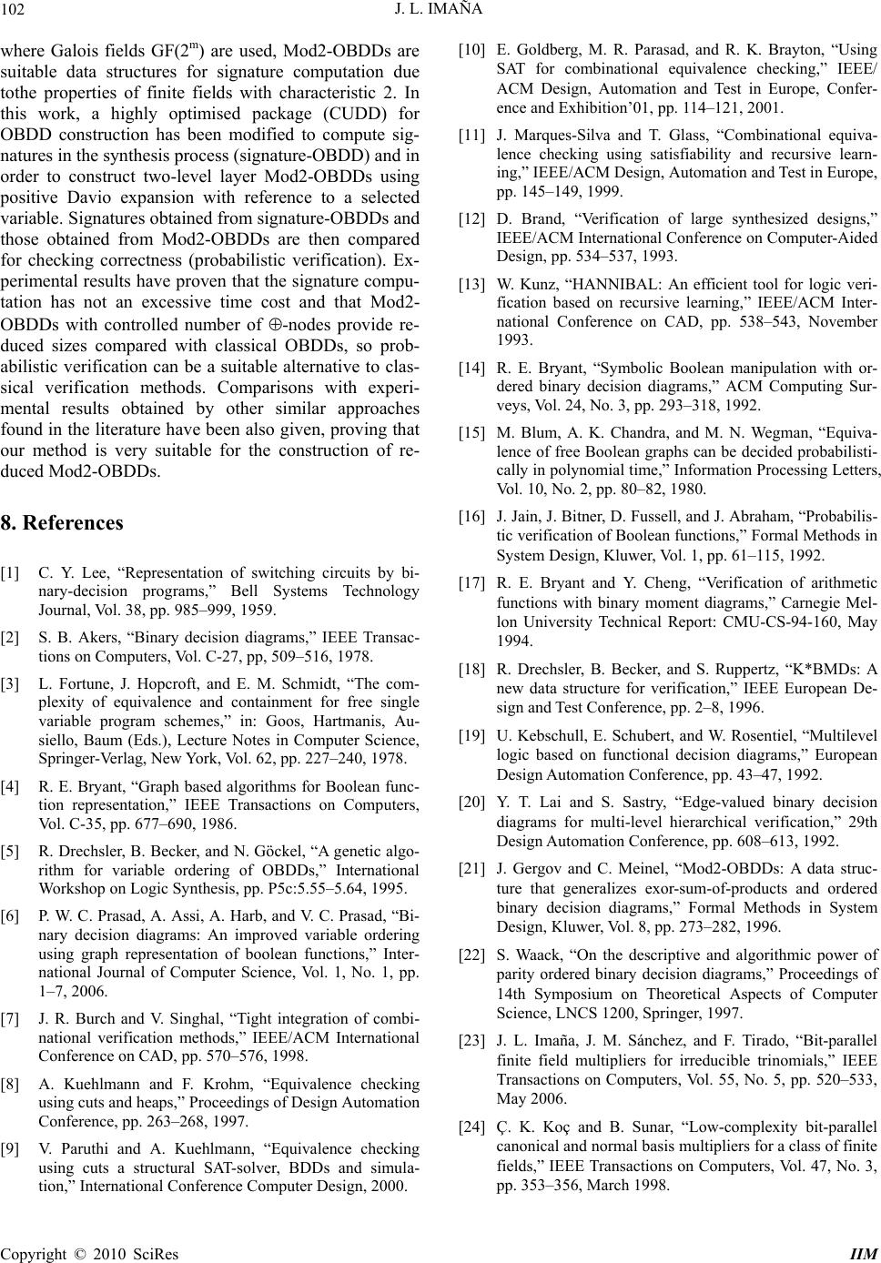 J. L. IMAÑA 102 where Galois fields GF(2m) are used, Mod2-OBDDs are suitable data structures for signature computation due tothe properties of finite fields with characteristic 2. In this work, a highly optimised package (CUDD) for OBDD construction has been modified to compute sig- natures in the synthesis process (signature-OBDD) and in order to construct two-level layer Mod2-OBDDs using positive Davio expansion with reference to a selected variable. Signatures obtained from signature-OBDDs and those obtained from Mod2-OBDDs are then compared for checking correctness (probabilistic verification). Ex- perimental results have proven that the signature compu- tation has not an excessive time cost and that Mod2- OBDDs with controlled number of -nodes provide re- duced sizes compared with classical OBDDs, so prob- abilistic verification can be a suitable alternative to clas- sical verification methods. Comparisons with experi- mental results obtained by other similar approaches found in the literature have been also given, proving that our method is very suitable for the construction of re- duced Mod2-OBDDs. 8. References [1] C. Y. Lee, “Representation of switching circuits by bi- nary-decision programs,” Bell Systems Technology Journal, Vol. 38, pp. 985–999, 1959. [2] S. B. Akers, “Binary decision diagrams,” IEEE Transac- tions on Computers, Vol. C-27, pp, 509–516, 1978. [3] L. Fortune, J. Hopcroft, and E. M. Schmidt, “The com- plexity of equivalence and containment for free single variable program schemes,” in: Goos, Hartmanis, Au- siello, Baum (Eds.), Lecture Notes in Computer Science, Springer-Verlag, New York, Vol. 62, pp. 227–240, 1978. [4] R. E. Bryant, “Graph based algorithms for Boolean func- tion representation,” IEEE Transactions on Computers, Vol. C-35, pp. 677–690, 1986. [5] R. Drechsler, B. Becker, and N. Göckel, “A genetic algo- rithm for variable ordering of OBDDs,” International Workshop on Logic Synthesis, pp. P5c:5.55–5.64, 1995. [6] P. W. C. Prasad, A. Assi, A. Harb, and V. C. Prasad, “Bi- nary decision diagrams: An improved variable ordering using graph representation of boolean functions,” Inter- national Journal of Computer Science, Vol. 1, No. 1, pp. 1–7, 2006. [7] J. R. Burch and V. Singhal, “Tight integration of combi- national verification methods,” IEEE/ACM International Conference on CAD, pp. 570–576, 1998. [8] A. Kuehlmann and F. Krohm, “Equivalence checking using cuts and heaps,” Proceedings of Design Automation Conference, pp. 263–268, 1997. [9] V. Paruthi and A. Kuehlmann, “Equivalence checking using cuts a structural SAT-solver, BDDs and simula- tion,” International Conference Computer Design, 2000. [10] E. Goldberg, M. R. Parasad, and R. K. Brayton, “Using SAT for combinational equivalence checking,” IEEE/ ACM Design, Automation and Test in Europe, Confer- ence and Exhibition’01, pp. 114–121, 2001. [11] J. Marques-Silva and T. Glass, “Combinational equiva- lence checking using satisfiability and recursive learn- ing,” IEEE/ACM Design, Automation and Test in Europe, pp. 145–149, 1999. [12] D. Brand, “Verification of large synthesized designs,” IEEE/ACM International Conference on Computer-Aided Design, pp. 534–537, 1993. [13] W. Kunz, “HANNIBAL: An efficient tool for logic veri- fication based on recursive learning,” IEEE/ACM Inter- national Conference on CAD, pp. 538–543, November 1993. [14] R. E. Bryant, “Symbolic Boolean manipulation with or- dered binary decision diagrams,” ACM Computing Sur- veys, Vol. 24, No. 3, pp. 293–318, 1992. [15] M. Blum, A. K. Chandra, and M. N. Wegman, “Equiva- lence of free Boolean graphs can be decided probabilisti- cally in polynomial time,” Information Processing Letters, Vol. 10, No. 2, pp. 80–82, 1980. [16] J. Jain, J. Bitner, D. Fussell, and J. Abraham, “Probabilis- tic verification of Boolean functions,” Formal Methods in System Design, Kluwer, Vol. 1, pp. 61–115, 1992. [17] R. E. Bryant and Y. Cheng, “Verification of arithmetic functions with binary moment diagrams,” Carnegie Mel- lon University Technical Report: CMU-CS-94-160, May 1994. [18] R. Drechsler, B. Becker, and S. Ruppertz, “K*BMDs: A new data structure for verification,” IEEE European De- sign and Test Conference, pp. 2–8, 1996. [19] U. Kebschull, E. Schubert, and W. Rosentiel, “Multilevel logic based on functional decision diagrams,” European Design Automation Conference, pp. 43–47, 1992. [20] Y. T. Lai and S. Sastry, “Edge-valued binary decision diagrams for multi-level hierarchical verification,” 29th Design Automation Conference, pp. 608–613, 1992. [21] J. Gergov and C. Meinel, “Mod2-OBDDs: A data struc- ture that generalizes exor-sum-of-products and ordered binary decision diagrams,” Formal Methods in System Design, Kluwer, Vol. 8, pp. 273–282, 1996. [22] S. Waack, “On the descriptive and algorithmic power of parity ordered binary decision diagrams,” Proceedings of 14th Symposium on Theoretical Aspects of Computer Science, LNCS 1200, Springer, 1997. [23] J. L. Imaña, J. M. Sánchez, and F. Tirado, “Bit-parallel finite field multipliers for irreducible trinomials,” IEEE Transactions on Computers, Vol. 55, No. 5, pp. 520–533, May 2006. [24] Ç. K. Koç and B. Sunar, “Low-complexity bit-parallel canonical and normal basis multipliers for a class of finite fields,” IEEE Transactions on Computers, Vol. 47, No. 3, pp. 353–356, March 1998. Copyright © 2010 SciRes IIM  J. L. IMAÑA Copyright © 2010 SciRes IIM 103 [25] R. Lidl and H. Niederreiter, “Finite fields,” Addi- son-Wesley, Reading, MA, 1983. [26] J. C. Madre and J. P. Billón, “Proving Circuit correctness using formal comparison between expected and extracted behaviour,” Proceedings of 25th ACM/IEEE Design Automation Conference, pp. 308–313, 1988. [27] P. A. Scott, S. E. Tavares, and L. E. Peppard, “A fast VLSI multiplier for GF(2m),” IEEE Journal on Selected Areas in Communications, Vol. 4, pp. 62–66, 1986. [28] C. Meinel and H. Sack, “-OBDDs–A BDD structure for probabilistic verification,” Pre-LICS Workshop on Prob- abilistic Methods in Verification (PROBMIV’98), Indi- anapolis, IN, USA, pp. 141–151, 1998. [29] F. Somenzi, “CUDD: CU decision diagram package,” Uni- versity of Colorado at Boulder. http://vlsi.colorado. edu/ ~ fabio/CUDD/. [30] K. S. Brace, R. L. Rudell, and R. E. Bryant, “Efficient implementation of a BDD package,” 27th ACM/IEEE Design Automation Conference, pp. 40–45, 1990. [31] K. M. Butler, D. E. Ross, R. Kapur, and M. R. Mercer, “Heuristics to compute variable orderings for efficient manipulation of ordered binary decision diagrams,” Pro- ceedings of 28th ACM/IEEE DAC, pp. 417–420, June 2001. [32] C. S. Yeh, I. S. Reed, and T. K. Truong, “Systolic multi- pliers for finite fields GF(2m),” IEEE Transactions on Computers, Vol. 33, No. 4, pp. 357–360, April 1984. [33] M. Fujita, H. Fujisawa, and Y. Matsunaga, “Variable or- dering algorithms for ordered binary decision diagrams and their evaluation,” IEEE Transactions on CAD, Vol. 12, No. 1, pp. 6–12, January 1993. [34] C. Meinel and H. Sack, “Improving XOR-Node place- ment for -OBDDs,” 5th International Workshop on Ap- plications of the Reed-Muller Expansion in Circuit De- sign, Starkville, Mississippi, USA, pp. 51–56, 2001. [35] C. Meinel and H. Sack, “Variable Reordering for - OBDDs,” International Symposium on Representations and Methodology of Future Computing Technologies (RM2003), Trier, Germany, pp. 135–144, 2003. |

