Int'l J. of Communications, Network and System Sciences
Vol.2 No.5(2009), Article ID:607,20 pages DOI:10.4236/ijcns.2009.25048
Incremental Network Programming for Wireless Sensors
Computer Science Division, University of California, Berkeley, California, USA
Email: {jaein,culler}@eecs.berkeley.edu
Received April 4, 2009; revised May 12, 2009; accepted July 5, 2009
Keywords: Network Programming, Incremental, Wireless Sensor Networks, Difference Generation,Rsync Algorithm
ABSTRACT
We present an incremental network programming mechanism which reprograms wireless sensors quickly by transmitting the incremental changes using the Rsync algorithm; we generate the difference of the two program images allowing us to distribute only the key changes. Unlike previous approaches, our design does not assume any prior knowledge of the program code structure and can be applied to any hardware platform. To meet the resource constraints of wireless sensors, we tuned the Rsync algorithm which was originally made for updating binary files among powerful host machines. The sensor node processes the delivery and the decoding of the difference script separately making it easy to extend for multi-hop network programming. We are able to get a speed-up of 9.1 for changing a constant and 2.1 to 2.5 for changing a few lines in the source code.
1. Introduction
Typically, wireless sensors are designed for low power consumption and small size and don’t have enough computing power and storage to support a rich programming development environment. Thus, the program code is developed on a more powerful host machine and is loaded onto a sensor node afterwards. The program code is usually loaded onto a sensor node through the parallel or serial port of the host machine; this is called in-system programming. In-system programming (ISP) is the most common way of programming sensor nodes because most microcontrollers support program loading through the parallel or serial port. However, ISP can only load the program code to one sensor node at a time. The programming time increases proportional to the number of wireless sensors to be deployed. During the development cycle of wireless sensor software, the source code can be modified for bug fixes or to add additional functionalities. With ISP, the cost of a software update is high; it involves all the efforts of collecting the sensor nodes placed at different locations and possibly disassembling and reassembling the enclosures. Network programming reduces these efforts by delivering the program code to each of the sensor nodes through the wireless links.
Network programming has been used since the introduction of TinyOS 1.1 release [1,2]. This implementation, XNP (Crossbow Network Programming), provides the basic capability of network programming; it delivers the program code to the sensor nodes remotely. However, it has some limitations: First, XNP does not scale to a large sensor network. XNP disseminates the program code only to the nodes that can be reached directly by the host machine. Therefore, the nodes outside the single hop boundary cannot be programmed. Second, XNP has a lower bandwidth compared than ISP. An experiment in [1] shows the programming time of XNP and ISP. In the experiment, we used a simple test application ‘XnpCount’ which has basic functionalities: network programming, counting numbers using LEDs and transmitting the number in radio packets. The version of ‘XnpCount’ we used was 37,000 bytes in size and required 841 XNP packets to transfer the entire program. The programming time of XNP was more than 4 times longer than that of ISP (Figure 1). When XNP updates the program code with another version, it sends the entire program code rather than the difference. This incurs the same program-
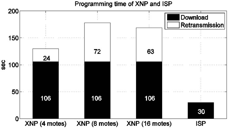
Figure 1. Programming time of crossbow network programming (XNP) and in-system programming (ISP).
ming time even when the difference is small. If the sensor nodes could build the program code image incrementally using the previous code image, the overall programming time can be reduced.
We present an incremental network programming mechanism which sends the new version of the program by transmitting the difference of the two program images. Unlike previous approaches, we generate the program code difference by comparing the program code in block level without any prior knowledge of the program code structure. This gives a general solution that can be applied to any hardware platform. We used the Rsync algorithm [3] to generate the difference. The Rsync algorithm finds the shared code blocks between the two program images and allows us to distribute only the key changes of the program. Originally, the Rsync algorithm was made for computationally powerful machines exchanging the update of binary files over a low-bandwidth communication link. We tuned the Rsync algorithm for wireless sensor network programming. First, we made the host program process expensive operations like building the hash table in favor of the sensor node. In order to rebuild the program image the sensor node simply reads or writes code blocks to flash memory.
Second, we structured the difference to avoid unnecessary flash memory accesses. In rebuilding the program image, the sensor node processes the script dissemination and the decoding in separate steps. This makes it easy to use dissemination protocols and to extend for multi-hop network programming. We are able to get a speed-up of 9.1 for changing a constant and 2.1 to 2.5 for changing a few lines in the source code over the non-incremental delivery.
The rest of the paper is organized as follows. Section 2 describes the in-system programming and the network programming as a background. Section 3 discusses the related work on wireless sensor network programming. Section 4 outlines incremental network programming and explains our first implementation. In Section 5, we use the Rsync algorithm to generate the program and show how this implementation improves performance. In Section 6, we discuss the extension to the script delivery which makes program delivery more reliable and faster. Finally, we conclude this thesis with Section 7.
2. Background
2.1. In-System Programming
The program development for wireless sensors starts with writing the source code. For the Berkeley sensor platform, the source code is written in the nesC programming language. Once the source code is successfully compiled, the binary code is generated (main.exe). The binary code is further converted to the Motorola SREC format (main.srec) and is then available for loading. The Motorola SREC format is an ASCII representation of binary code and each line of an SREC file contains the data bytes of the binary code with additional house keeping information (Figure 2).
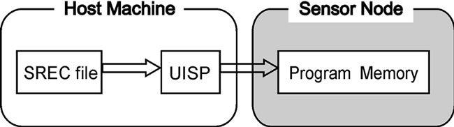
With ISP, the binary code (SREC format) is loaded onto a sensor node through the direct connection (e.g. parallel port) from the host machine. The host programming tool (uisp) sends a special sequence of bytes that places the microcontroller of the sensor node in programming mode. While the microcontroller is in programming mode, the data bytes sent by the host programming tool are written directly to the program memory of the microcontroller (Figure 3(a)).
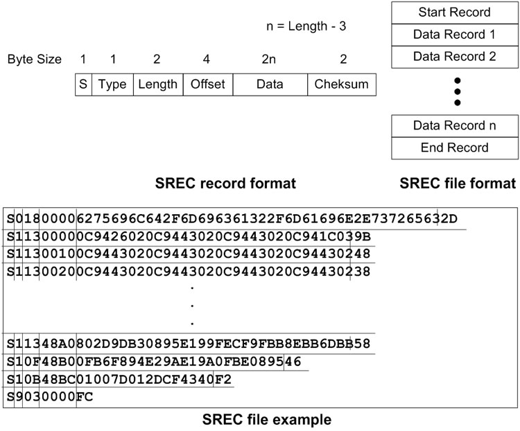
Figure 2. Format of SREC file and its records with an example.
 (a)
(a)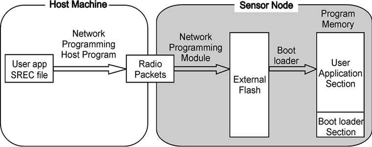 (b)
(b)
Figure 3. Steps for in-system programming and network programming.
2.2. Network Programming
Network programming takes a different approach to loading the program code. Rather than writing the program code directly to program memory, network programming loads the program code in two steps. First, it delivers the program code to the sensor nodes. Second, it makes the sensor nodes move the downloaded code to program memory (Figure 3(b)).
In the first step, the network programming module stores the program code in external storage. Since the network programming module runs in user level as a part of the main application code, it does not have the privilege to write the program code into program memory. In the case of XNP, the network programming module writes the program code to the external flash memory outside program memory. The external flash memory of a MICA2/MICA2DOT mote is 512KB in size and is big enough for any application code (the maximum size of 128KB). During program delivery, part of the code may be missing due to the packet loss. The network programming module requests for any missing records of the program code to make sure that there are no missing records.
In the second step, the boot loader copies the program code from external flash memory to program memory. The boot loader is a program that resides in the high memory area (which we call the boot loader section) of an ATmega128 microcontroller and has the privileges to write data bytes to the user application section of program memory [4]. The boot loader starts execution when it is called by the network programming module. After it copies the program code from the external flash memory to program memory, it restarts the system.
In the paragraphs above, we assumed that the sensor nodes can update the current program image through network programming. However, a sensor node cannot be network programmed until it has the network programming module and the boot loader. Thus, we need to load the initial program code and the boot loader with ISP.
3. Related Work
3.1. Wireless Sensor Network Programming
XNP [1,2] is the network programming implementation for TinyOS that was introduced with 1.1 releases version. XNP supports basic network programming broadcasting the program code to multiple nodes in a single hop. However, it doesn’t consider a large sensor network and incremental update.
MOAP [5] is a multihop network programming mechanism and their main contributions are its code dissemination and buffer management. For code dissemination, they used the Ripple dissemination protocol which disseminates the program code packets to a selective number of nodes without flooding the network with packets. For buffer management, they used a sliding window scheme which maintains a window of program code and allows lost packets within the window to be retransmitted. The sliding window uses a small footprint so that packets can be processed efficiently in on-chip RAM. MOAP was tested on the EmStar simulator and MICA2 motes.
Deluge [6] is a multihop network programming protocol that disseminates program code in an epidemic fashion to propagate program code while regulating the excess traffic. In order to increase the transmission rate, Deluge used optimization techniques like adjusting the packet transmit rate and spatial multiplexing. Unlike MOAP, Deluge uses a fixed sized page as a unit of buffer management and retransmission. Deluge was tested with the TOSSIM simulator [7] and MICA2 motes.
Reijers, et al. [8] developed an algorithm that updates binary images incrementally. With the algorithm, the host program generates an edit script to describe the difference between the two program code images. The sensor nodes build the program image after interpreting the edit script. The edit script consists of not only simple operations like copy and insert but also more complex operations (address repair and address patch) that modify the program code at the instruction level. This helps minimizing the edit script size. As an evaluation, this paper considers only the reduced script size on the host side. Since operations like address repair and address patch incur memory intensive EEPROM scanning, the experiments should have demonstrated the overall programming time in a sensor simulator or in a real sensor node.
Kapur, et al. [9,10] implemented a version of incremental network programming based on the algorithm of Reijers, et al [8]. Their implementation is composed of two parts: the diff encoder on the host side and the diff decoder on the sensor node side. The diff encoder generates the difference for the two versions of code at the instruction level using copy, insert and repair operations. The difference script is delivered to the sensor node using MOAP [5] which was developed for reliable code dissemination. Then, the sensor node rebuilds the program code after decoding the downloaded script.
These two works on incremental network programming minimized the script transmission at the cost of program modification at the instruction level. In contrast, the implementation in this paper put less computational complexity on the sensor nodes. The difference generation, which is costly, is handled by the host program. The sensor nodes simply write the data blocks based on the script commands and this can be applied to less powerful sensor nodes.
While the examples above disseminated the program code in native binary code, Maté [11] distributes the program code in virtual machine instructions which are packed in radio packets. While XNP transmits the binary code that contains both the network programming module and the application, Maté only transmits the application code. This allows Maté to distribute the code quickly. One drawback of Maté is that it runs the program code only in virtual machine instructions and a regular sensor application needs to be converted to virtual machine instructions before execution.
Trickle [12] is an improvement over Maté. In Maté, each sensor node floods the network with packets to distribute the code and this can lead to network congestion but the algorithm can be used for a large sensor network. Trickle addresses this problem by using a “polite gossip” policy. Each sensor node periodically broadcasts a code summary to its local neighbors and stays quiet if it has recently heard a summary identical to its own summary. The sensor node broadcasts an update only when it hears from an older summary than its own.
3.2. Remote Code Update outside Wireless Sensor Community
Outside the sensor network community, there have been efforts to update program code incrementally. Emmerich et al. [13] demonstrated updating XML code in an incremental fashion. Specifying the update in XML is easier than a binary image because XML is a structured markup language and it allows specifying the update without changing the structure of the rest of the code. In contrast, inserting or replacing code blocks in binary code affects the rest of the code.
The cases of synchronizing general form of unstructured files can be found with Rsync and LBFS. Rsync [3] is a mechanism to efficiently synchronize two files connected over a low-bandwidth, bidirectional link. To find matching blocks between the two files, we can divide the first file into fixed sized blocks of B bytes and calculate the hash for each block. Then, we scan the second file and form a B byte window at each byte. After that we compare the hash for the window with hash values of all the blocks in the first file. This does not work that well. If the hash is expensive to calculate, finding the matching blocks will take long time. If the hash can be computed cheaply but with possible false matches, we may not find the correct block. The key idea of Rsync is to use two levels of hashes, rolling checksum (fast hash) and hash (strong hash) to make the computation overhead manageable while finding the matching blocks with high probability. Rsync calculates the rolling checksum of the B byte window of the second file at each byte and computes the hash only when the rolling checksums of the two blocks match. Since the hash is computed only for the possible matches, the cost of calculating the hash is manageable and we can filter out the false match.
LBFS [14], another mechanism to synchronize two files in a low-bandwidth, bidirectional link, takes a slightly different approach. Rather than divides a file into fixed blocks, LBFS divides each file into a number of variable sized blocks and computes the hash over each block. To find matching blocks between the two files, LBFS just compares these hashes (SHA-1 hash). The key idea of LBFS is in dividing a file into variable sized blocks. LBFS scans a file and forms a 48-byte window at each byte and calculates a 13-bit fingerprint. If the fingerprint matches a specific pattern, that position becomes the breakpoint of the block. This scheme has a property that modifying a block in a file does not change the hash values of the other blocks. When we are going to send a new version, we can just compare the hash values of each variable block and send only the non-matching blocks.
The mechanism patented by Metricom Inc. [15] disseminates the program code over multihop networks in an efficient way using an epidemic protocol. When a node V has a new version of code, it tells its neighbors that a new version of code is available. On hearing the advertisement from V, one of V’s neighbor, P, checks whether it has the newly advertised version. If it doesn’t have the version, P requests V transmit the version of code. After that, V starts sending program code and finishes when it doesn’t hear any requests. With this scheme, a sensor node can distribute the program code without causing much network traffic.
4. Design and Implementation
To design an incremental network programming mechanism, we need to consider some factors that affect performance. Compared to other sensor applications, network programming keeps a large amount of data in the sensor nodes contributing to long programming time. Since programming time is proportional to data size, reducing the amount of transmission data will improve programming time. External flash memory which is used for program storage also limits performance. The downloaded code is stored in the external flash memory because there is not enough space in on-chip memory. However, this external flash memory is much slower than the on-chip SRAM. For better performance, access to external memory should be made only when it is necessary. Caching frequently accessed data can help reducing flash memory accesses.
 (a)
(a)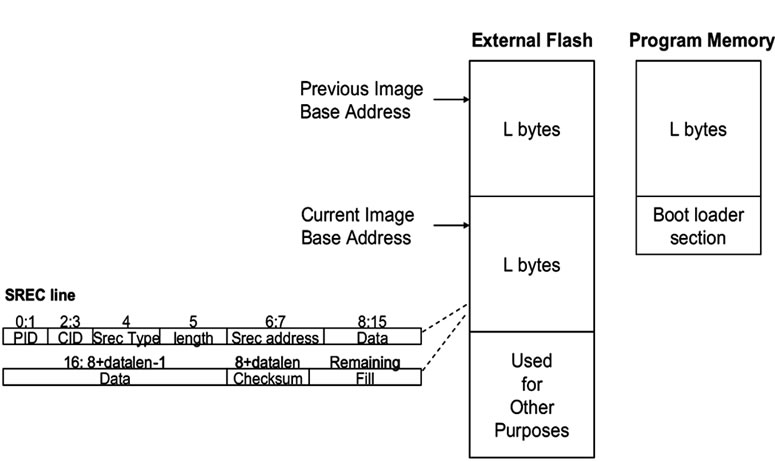 (b)
(b)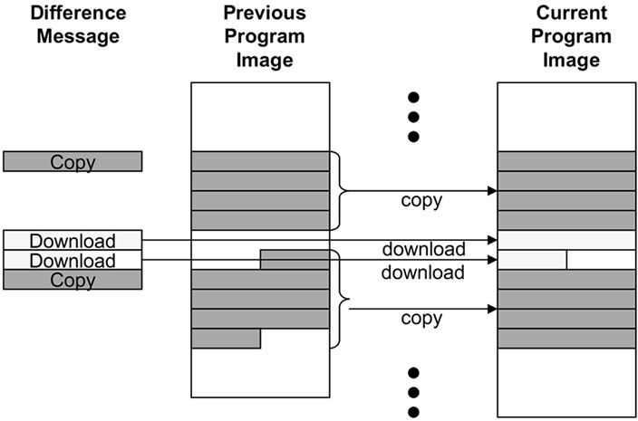 (c)
(c)
Figure 4. Steps for incremental network programming.
Another consideration is how much functionality is to be processed in the sensor nodes. More sophisticated algorithms could reduce overall programming time by reducing network traffic, but at the cost of higher complexity computation and memory accesses.
Finally, the design should be simple so that it can be understood and diagnosed without difficulty.
4.1. Design: Fixed Block Comparison
As a starting point, we can design a version of incremental network programming by extending XNP. This consists of two main parts: 1) difference generation and code delivery, 2) storage organization and image rebuild.
4.1.1. Difference Generation
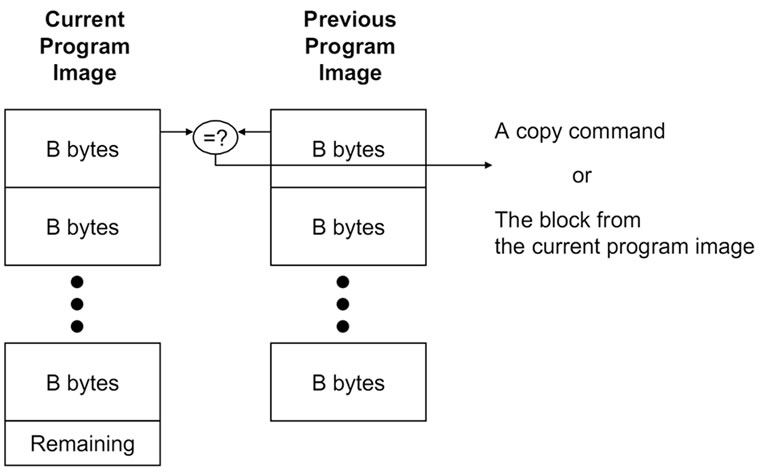
To generate the program difference, the host program compares each fixed sized block of the new program image with the corresponding block of the previous image. We set the block size as the page size of the external flash memory (256 bytes). The host program sends the difference as messages while it compares the two program versions. If the two corresponding blocks match, the host program sends a CMD_COPY_BLOCK message. The message makes the network programming module in the sensor node copy the block of the previous image to the current image. When the two blocks don’t match, the host program falls back to the normal download; it sends a number of CMD_DOWNLOADING messages for the SREC records of the block (Figure 4(a)).
The idea is that we can reduce the number of message transmissions by sending a CMD_COPY_BLOCK message instead of multiple CMD_DOWNLOADING messages when most of the blocks are the same between the two program images.
4.1.2. Operations
Table 1 shows the message types used for incremental network programming. Based on XNP messages, we made the following extensions for incremental network programming as in Figure 5.
• Start Download: CMD_START_DOWNLOAD_IN CR message notifies the beginning of network programming in incremental mode. This message specifies not just the program ID of the current program but also the program ID of the previous program to ensure that the sensor node has the same program image as the host program.
• Download: Two operations CMD_DOWNLOADING Table 1. Message types for incremental network programming.
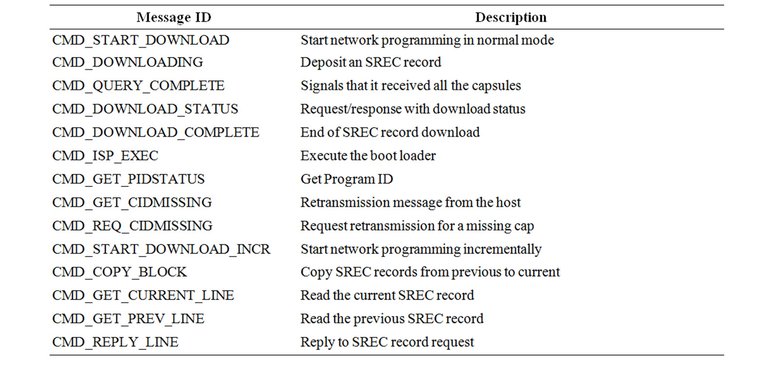
• and CMD_COPY_BLOCK are used to transmit the program image difference.
• Query and Reboot: The formats of query, reply and reboot messages are the same as XNP messages.
Debugging Messages: CMD_GET_CURRENT_LINE and CMD_GET_PREV_LINE messages request the SREC record at the specified line. In response, the sensor node sends CMD_REPLY_LINE message.
4.1.3. Storage Organization
XNP stores the program image in a contiguous memory chunk in the external flash memory. Fixed Block Comparison scheme extends this by allocating two memory chunks, one for the previous program image and the other for the scratch space where the current image will be built (Figure 4(b)).
The two memory chunks have the same structure and they are swapped once the newly built program is loaded onto program memory. The current program image is now considered the previous image and the space for the previous image is available for the next version of program image. For the two memory chunks, two base address variables are maintained in the flash memory. By changing the address values in these variables, the two memory chunks can be swapped.
This memory organization has an advantage that it provides the same view of the memory as XNP and minimizes the effort of rewriting the boot loader code. The boot loader code of XNP reads the program code assuming that it is located at a fixed location in external flash memory. We modified the boot loader so that it reads the program code from the base address passed by an inter-process call argument. Thus, the boot loader can read the program code from any memory chunk depending on the base address value passed by the network program module.
However, this scheme does not use the external flash memory space economically. It allocates 256 KB of space regardless of the program code size (128 KB of space both for the current and the previous image). This accounts for 50% of the flash memory space of a MICA2 mote and leaves less space for data logging.
4.1.4. Image Rebuild
The program image is built in a straightforward way. The network programming module of the sensor node builds the program image by writing the SREC records based on a list of download and copy messages (Figure 4(c)).
The download message makes the sensor node deposit the data bytes from the message into the program image. The format of a download message is the same as an XNP download message. The capsule ID field specifies the location (line number) in the current program image and the data represents the data bytes to be written.
The copy message is for incremental network programming making the sensor node copy the SREC lines of a block in the previous program image to the current program image. The capsule ID field specifies the location of the first SREC record to be copied and the block size field specifies the number of SREC records to be copied.
4.2. Implementation
4.2.1. Difference Generation and Code Delivery
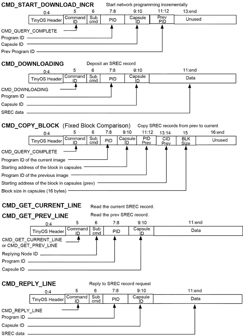
Figure 5. Message format for incremental network prgramming.
The host program, which is in charge of program image loading, difference generation and code delivery, is composed of the following classes:
• xnp: GUI, main module
• xnpUtil: loads the program image, generates the difference and provides utility functions
• xnpQry: processes queries and retransmissions
• xnpXmitCode: processes code delivery
• xnpMsg: defines the message structure
• MoteMsgIF: abstracts the interface to the serial forwarder If the user selects the download command after loading the current and the previous program images, the xnp class spawns the xnpXmitCode class. xnpXmitCode compares each pair of blocks in the current and previous images by calling xnpUtil.CompareBlocks. Depending on the result, it either sends a copy message (CMD_ COPY_BLOCK) or sends a download message (CMD_ DOWNLOADING) for each line of the current block. Figure 6 illustrates this process.
4.2.2. Handling the Message
The network programming module for a sensor node is composed of the following components: XnpM.nc (implementation), XnpC.nc (configuration), Xnp.nc (interface), Xnp.h, XnpConst.h (constant definition). The implementation module has an event driven structure (Figure 7). When a XNP message arrives, ReceiveMsg. receive() sets the next state variable (cNextState) as the appropriate value and posts the NPX_STATEMACHINE() task. This message loop structure readily processes an incoming message without interrupting the message currently being processed.
One of the difficult parts was handling split phase operations like external flash reads and writes. To read an SREC record from external flash, EEPROMRead.read() is called. But this function returns before actually reading the record. The event handler EEPROMRead.readDone() is called when the record is actually read. And we specify the next state in the event handler. This makes us use multiple intermediate states to process an incoming message. Table 11 and 12 in the Appendix show which states were used to handle each message type.
To estimate the cost of message handling, we counted the source code lines for the two most important messages, CMD_DOWNLOADING, and CMD_COPY_BLOCK. The number of lines are 136 and 153 respectively. Table 13 shows the cost at each step of the message loop.
4.2.3. Calling the Boot Loader
XnpM builds the new program image based on the previous version and the difference. In order to transfer the new image to program memory, we modified the XnpM module and the boot loader. The part of the XnpM code that executes the boot loader is shown in Figure 8. wEEProgStart is passed as the starting address of the new program image in the external flash memory. Here, 0x1F800 is the starting address of the boot loader in the Atmega128 microcontroller memory map. The boot loader uses the address passed as a parameter to access the new image.
4.3. Experiment Setup
To evaluate the performance of this design choice, we will count the number of block or packet transmissions of the test set. We considered the following five cases as a test scenario:
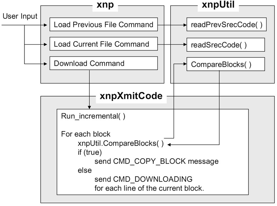
Figure 6. Host program for incremental network programming.
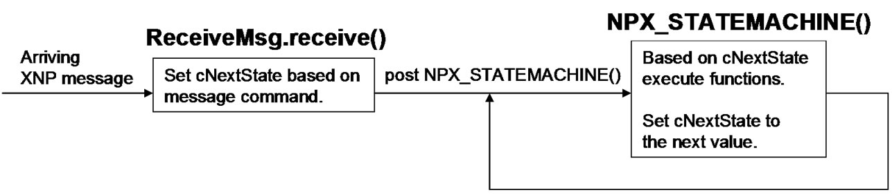
Figure 7. Network programming module message handling.
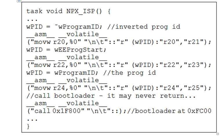
Figure 8. Passing the starting address of the new program image to the boot loader.
4.3.1. Case 1 (Changing Constants)
This is the case with the minimum amount of change. We modified the constant in XnpBlink that represents the blinking rate of the LED. XnpBlink is an application written for demonstrating network programming. It accepts network programming and blinks the red LED. The following code segment shows the modification to this program.
4.3.2. Case 2 (Modifying Implementation File)
This is a more general case of program modification. We added a few lines of code to the XnpCount program. XnpCount is a simple network programmable application. It counts a number, displays the number in its LEDs and broadcasts the number in radio packets. The following code segment shows the modification to this program.
4.3.3. Case 3 (Major Change)
In this case, we used two programs, XnpCount and XnpBlink as input to generate the difference. The difference is larger than the first two cases, but these two applications still share a large portion of the source level code (Table 2).
4.3.4. Case 4 (Modifying Configuration Filecommenting out IntToLeds)
We commented out a few lines in the XnpCount program
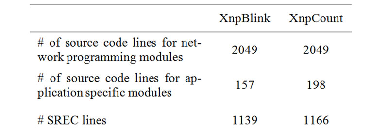
Table 2. Code size of test applications.
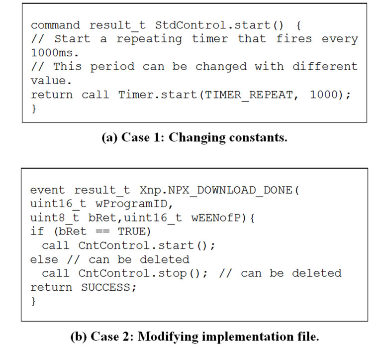
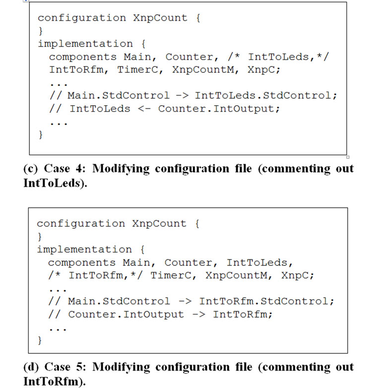
Figure 9. Test scenarios.
so that we do not use the IntToLeds module. IntToLeds is a simple module that takes an integer input and displays it on the LEDs of the sensor node. The following code segment shows the modification to this program.
4.3.5. Case 5 (Modifying Configuration Filecommenting out IntToRfm)
We commented out a few lines in XnpCount program so that we do not use the IntToRfm module. IntToRfm takes an integer input and transmits it over radio. Since commenting out IntToRfm forces the radio stack components not to be used, we expect a larger change in the program image than commenting out the IntToLeds module.
4.4. Results
To evaluate the performance of Fixed Block Comparison, we estimated the transmission time for each scenario. The host program calculates the estimated transmission time by counting how many download and copy messages it has sent. If it takes tdown to send a download message and tcopy to send a copy message, then the transmission time for Fixed Block Comparison, T, can be calculated as follows:
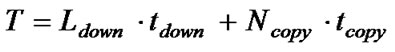
where Ldown is the number of SREC lines sent by download messages and Ncopy is the number of copy messages. As a baseline for comparison, we can also calculate the transmission time for non-incremental delivery as follows:
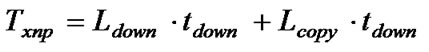
where Lcopy is the number of SREC lines to be copied by a copy message. We found values for tdown and tcopy after a number of trials. We set them as 120 ms and 300 ms respectively. Table 3 shows the parameters used for estimating the performance.
Next, we measured the transmission time by reading the system clock values. Table 4 shows the estimation and measurement data.
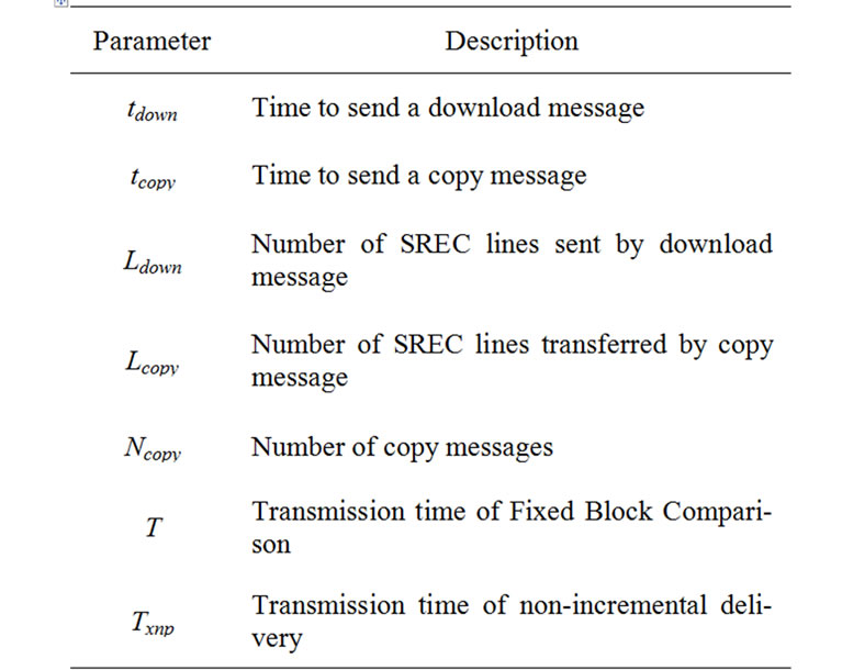
Table 3. Parameters for performance evaluation.
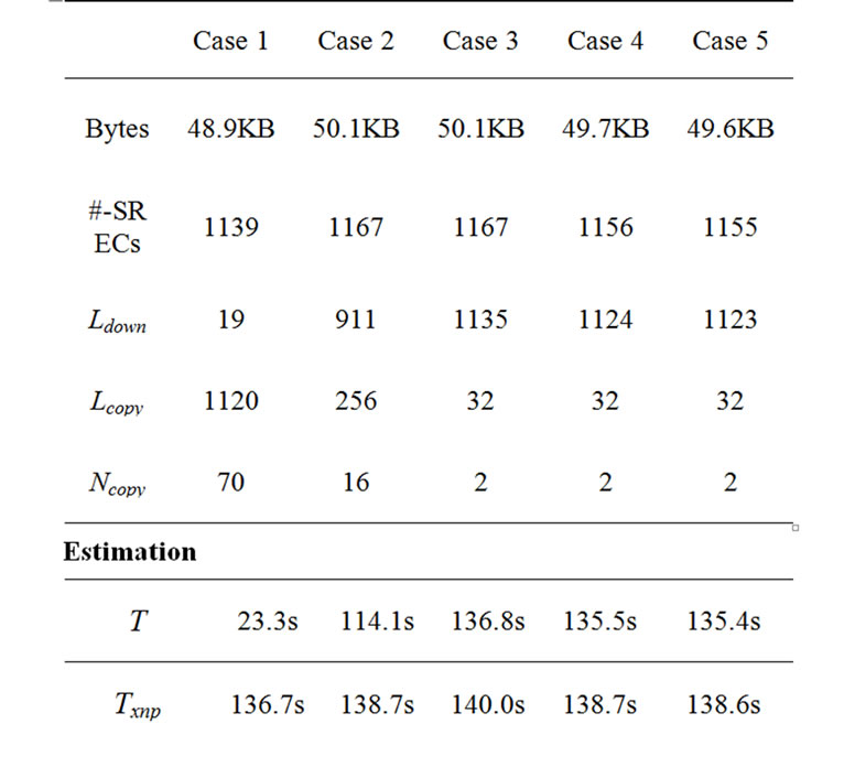
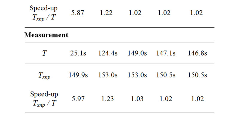
Table 4. Transmission time for each case.
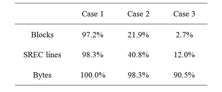
Table 5. Level of code sharing in blocks, lines and bytes.
In Case 1, the difference between the two program images is small. Most SREC lines (1120 out of 1139) are transferred by copy messages and the speed-up (Txnp / T ) is about 5.9.
In Case 2, where we added a few lines to the source code, we find that less than a quarter of the SREC lines are transferred by copy messages (256 out of 1167) and the speed-up is 1.2.
In Case 3, only 32 out of 1167 lines are transferred by copy messages and the speed-up is about 1.03. Although XnpBlink and XnpCount share much at the source code level, they share little at the binary code level. The main reason is that XnpCount uses the radio stack components while XnpBlink does not. The radio stack is one of the most important modules in TinyOS, and it takes a large number of source code lines.
In Case 4 and 5, where we commented out the IntToLeds and the IntToRfm components in the configuration file XnpCount.nc, we find that only a small number of lines are transferred by copy messages and the speed-up is very small (1.02 for each case).
Fixed block comparison was not so effective for incremental network programming. It works well when the program structure doesn’t change (Case 1). But, the level of sharing was low when we added a few lines of code (Case 2), which we think is a more general case of program modification.
We want to see why we have such a small level of binary code sharing. Does the program code completely change after the source modification, or does the program code still have much similarity at the byte level? To investigate further, we compared the program code at different levels: blocks (Fixed Block Comparison), SREC lines and bytes.
To compare the program code in SREC lines, we used the UNIX diff command. diff takes two ASCII files and describes how one file can be transformed to the other. To compare the program code at the byte level, we extracted the data bytes from an SREC file and stored each data byte in a line of the temporary file. We then used the UNIX diff to find the difference between the two byte list files.
Table 5 shows that Case 2 and Case 3 have a much higher level of sharing at the byte level than at the block level. For Case 2, most of the binary code was similar at the byte level (98.3%) while a small number of blocks were shared at the block level (21.9%). This implies that modifying the source code shifts the binary program code, but the program code bytes are still preserved. We can think of two ways to address this problem.
One approach is to place the shared code at a fixed location in the binary code with the help of the compiler. We can insert compiler directives and inline function calls. Then, the compiler recognizes the network programming module and determines its location in topological order.
Another approach is to utilize code sharing without modifying the code. As Table 5 suggests, much of the binary code is shared at byte level. By comparing the two binary images with a variable size boundary like Rsync [3] and LBFS [14], we can find more chances of code sharing.
5. Optimizing Difference Generation
Fixed Block Comparison, our first design choice for incremental network programming, was not effective in reducing data transmission traffic. It worked well only when the modified program image had the same structure as the previous program image. When additional lines are inserted into the source code, the program image is shifted and does not match the previous program image at the fixed sized block boundary.
In this section, we use the Rsync algorithm to generate the difference and rebuild the program image. The Rsync algorithm was originally made for efficient binary data update in a low bandwidth computer network. We expect the Rsync algorithm to find more matching blocks than the fixed block comparison because it compares the program image block at an arbitrary position.
5.1. Design
5.1.1. Difference Generation
The host program generates the difference using the Rsync algorithm as in Figure 10(a).
1) The Rsync algorithm calculates a checksum pair (checksum, hash) for each fixed sized block (e.g. B bytes) of the previous program image. And the checksum pair is inserted into a lookup table.
2) Rsync reads the current program image and calculates the checksum for the B byte block at each byte. If it finds a matching checksum in the lookup table, Rsync calculates the hash for the block and compares it with the corresponding entry in the table. If the hash also matches, the block is considered a matching block.
3) Rsync moves to the next byte for comparison if the block doesn’t have a matching checksum or hash. A region of bytes that doesn’t have any matching blocks is tagged as a non-matching block and needs to be sent explicitly for rebuilding.
Figure 10(a) illustrates how the Rsync algorithm captures a matching block. Suppose there is a shift by a modification operation in the middle of the program image. Rsync forms a B byte window and calculates the hash for it. If the modified bytes are different from any blocks in the previous program image, there is a high probability that the hash of the modified bytes won’t match any hash table entry. Rsync moves the window one byte at a time and calculates the checksum for any possible match. It doesn’t match until Rsync starts to read unmodified blocks. At this moment, Rsync has found a matching block.
5.1.2. Program Code Storage and Rebuild
As with the case of fixed block comparison, we maintain two memory chunks in a sensor node to build the program image from the previous program image and the difference. The difference consists of a list of matching and non-matching blocks.
The host program sends a CMD_COPY_BLOCK message for each matching block in the difference. After hearing the message, the sensor node copies the block from the previous image to the current image. The block size of a copy message is a multiple of a SREC line and the sensor node copies each SREC line iteratively. Since the block from the previous image can be mapped to any location in the current image, the offset address field of the SREC record needs be modified (Figure 10(b)).
For each non-matching block in the difference, the host program sends one or more download (CMD_ DOWNLOADING) messages. When a non-matching block is bigger than a single SREC record (16 bytes), the block is divided into multiple fragments and each fragment is sent in a download message. The data bytes of a download message can be shorter than a full SREC record if the non-matching block is not a multiple of 16 bytes. The host program does not fill the remaining bytes. This is to avoid extra flash memory accesses although the resulting program image can have a different layout from the original program image (Figure 10(c)).
Unlike fixed block comparison, we use the base and current program version to generate the program code incrementally. If we rebuild the current program image by comparing the last version and the current version, the host program and the sensor node may have different code leading to an incorrect program build. Instead, we compare the base and the current program version. This ensures that the sensor node reads the same data bytes as the host program.
5.1.3. Operations
We modified the format of CMD_COPY_BLOCK to specify the starting byte address of each copy block(Figure 11). When the Rsync algorithm generates the difference, the starting byte address of each block may not be a multiple of the SREC record size. We need to specify the starting byte address as well as the CID to correctly copy SREC records.
5.2. Implementation
5.2.1. Difference Generation
We used Jarsync [16] for the Rsync algorithm implementation. The host program calls the following methods to generate the difference: Rdiff.makeSignatures() and Rdiff.makeDeltas(). makeSignatures() calculates the checksum pair for each block in the image file and returns a list of checksum pairs. makeDeltas() compares the two image files and returns the difference as a list of matching blocks and unmatched blocks. Since these Jarsync methods assume a flat data file as input, the host program extracts only the data bytes from the SREC program image file and stores them in a temporary file before it calls the Jarsync module.
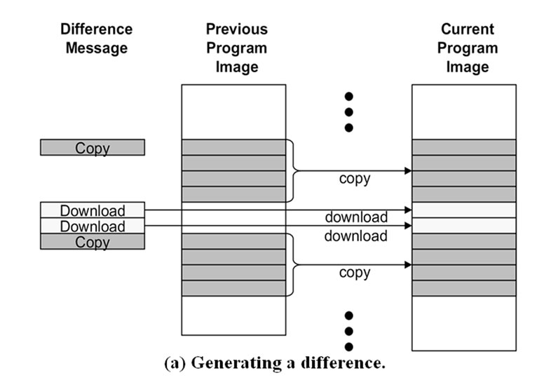
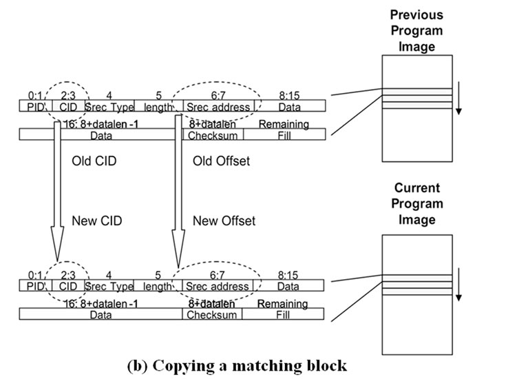
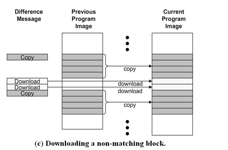
Figure 10. Steps for incremental network programming with Rsync difference generation.
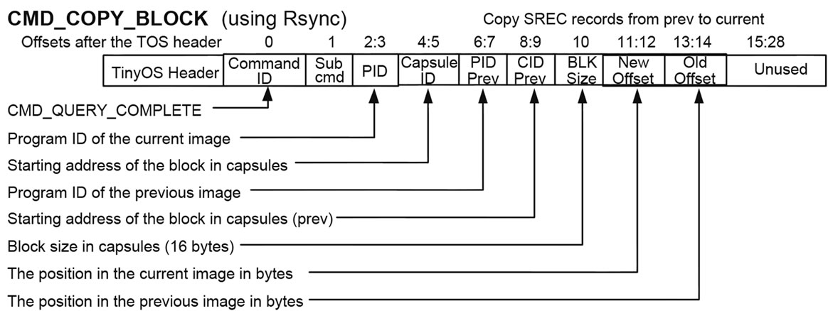
Figure 11. Message format for incremental network programming with Rsync difference generation.
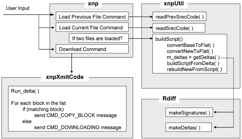
Figure 12. Host program for Rsync difference generation.
The difference returned by makeDeltas() needs postprocessing. The data bytes of an unmatched block can be an arbitrary size, but a download message can contain only up to 16 bytes. The host program divides an unmatched block into multiple blocks so that the data bytes of each block can fit in an SREC record. List entries for matching blocks are also postprocessed. Two matching blocks at consecutive locations are merged into a bigger block and this reduces the number of message transmissions.
5.2.2. Program Code Storage and Rebuild
The rebuilt program can be different from the original file due to the missing packets. If the host program sends a query for the missing record (CMD_GET_ CIDMISSING), the sensor node scans the current program section of external flash memory. Each record contains program ID (PID) and the capsule ID (CID, sequence number) fields. The PID should match the PID advertised at the start of incremental network programming (CMD_ START_DOWNLOAD_INCR). The CID field should match the line number where the record is written to. If either PID or CID does not match, the sensor node considers this a missing record and requests the retransmission of the SREC record. The host finds the missing record and sends it back. Then, the sensor node can fill the hole.
When the sensor node requests the retransmission of a missing SREC record, it specifies the missing record by CID field. Since the rebuilt program image can have a different layout from the original program file, just reading the specified record from the original program file oes not return the correct data. To address this issue, the host program rebuilds the new program with the same layout as the program image to be built in a sensor node.
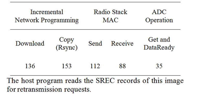
Table 6. Complexity of incremental network programming.
5.2.3. Code Complexity
To estimate the complexity of our implementation, we counted the source code lines in the the XnpM.nc file. A CMD_DOWNLOADING message costs 136 lines and a CMD_COPY_BLOCK message (for Rsync) costs 153 lines. The details are shown in Table 13. These numbers are comparable to those of other TinyOS modules. Sending and receiving radio packets are handled in several modules and CC1000RadioIntM.nc is a core module. A send operation takes 112 lines and a receive operation takes 88 lines in this module. As another example, we analyzed the ADCM.nc module which handles the reading of data from an ADC channel. It takes 35 lines to get a byte of data with ADCM.nc. Table 6 summarizes this.
5.3. Results
To evaluate the performance of incremental network programming with the Rsync algorithm, we estimated and measured the transmission time for three cases: 1) changing a constant in XnpBlink, 2) adding a few lines in XnpCount and 3) transforming XnpBlink to XnpCount. Table 7 shows the results.
In Case 1, most SREC records (1116 lines out of 1120) were transferred and the speed-up over non-incremental delivery was 6.25 (measurement). This is almost the same as the speed-up for Fixed Block Comparison (Case 1 in Figure 13).
In Case 2, 954 lines out of 1154 lines were transferred by copy messages and the speed-up over non-incremental delivery was 2.44 (measurement). Whereas Fixed Block Comparison has a speed-up of 1.2 (Case 2 in Figure 13). The improved speed-up was caused by the efficient difference generation of the Rsync algorithm.
In Case 3, the level of sharing was much smaller and the speed-up was 1.04 (measurement). We have some number of copy messages (85 messages), but they cover only a small number of blocks and are not so helpful in reducing programming time.
In Case 4, 814 lines out of 1140 lines were transferred by copy messages and the speed-up over non-incremental delivery was 1.92 (measurement). In contrast, the speed-up with Fixed Block Comparison was almost negligible (1.02).
In Case 5, 276 lines out of 1140 lines were transferred by copy messages and the speed-up over non-incremental delivery was quite small – 1.06 (measurement). Both Case 4 and Case 5 commented out a few lines in the configuration file. But, in Case 5, commenting out the IntToRfm component caused the radio stack to not be used and this changed the layout of the program image file a great deal.
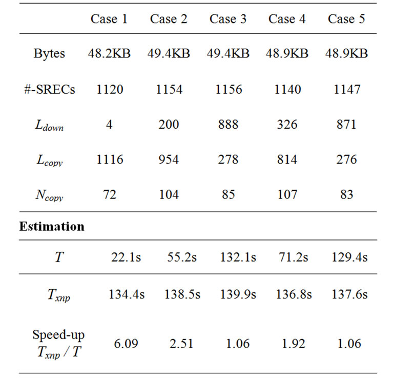
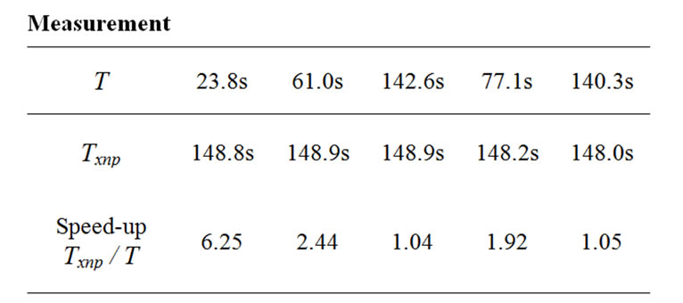
Table 7. Transmission time with the Rsync algorithm.
Estimation
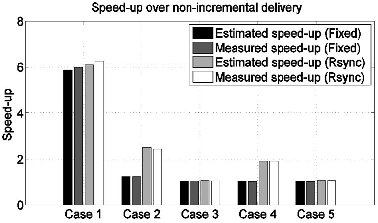
Figure 13. Speed-up in programming time for incremental network programming with and without Rsync difference generation.
In summary, using the Rsync algorithm achieves a speed-up of 6 for changing the constant and 2.4 for adding a few source code lines. These numbers are larger than those of Fixed Block Comparison, but using the Rsync algorithm is not still effective with a major code change.
As for the results in Table 7, we have some comments. First, we can ask why 4 SREC lines were transmitted as download messages in Case 1 when we changed only a constant in the source file. One of the reason is that the network programming module includes a timestamp value that is given at compile time. This ensures that each program image is different each time we compile the program. Another reason is that the previous SREC file was not aligned in the SREC record boundary at the end of the file. When we convert the SREC file to a flat file for Rsync, the layout changes.
Another question is why we sent 72 copy messages even though we could send fewer messages. In our design, the sensor node copies the program image blocks after hearing a copy message. To bound the execution time, we made each copy message handle up to 16 SREC lines (256 bytes).
6. Optimizing Difference Delivery
Compared to Fixed Block Comparison, the Rsync algorithm achieves shorter programming time by efficiently finding the shared blocks between the two binary code files. However, we can find some things to improve:
First, the network programming module transfers only a limited number of SREC records for each copy message. This is to bound the running time of a copy message so that the network programming module finishes processing a copy request before it receives another request.
Second, the network programming module interprets a copy request right after it receives the request without saving the request. In case there is a missing command, the network programming module has to check the rebuilt program image because it hasn’t stored the script commands. Since the network programming module does not know whether a missing hole was caused by a missing copy message or a number of download messages, it sends a retransmission requests for each missing record from the current program image. This will take more time than retransmitting only the missing command.
Thus, we propose extending the implementation of Section 5 as follows:
1) The sensor node receives all the commands for the script.
2) The sensor node checks for any missing records in the script.
3) The sensor node starts to decode script records in response to the script decode message.
6.1. Design
6.1.1. Operations
Since the script commands are stored in the storage space of the sensor node, we modified CMD_DOWNLOADING message to send script messages as in Figure 14. This has an advantage that we can reuse most of the code for handling normal data records to process the script commands.
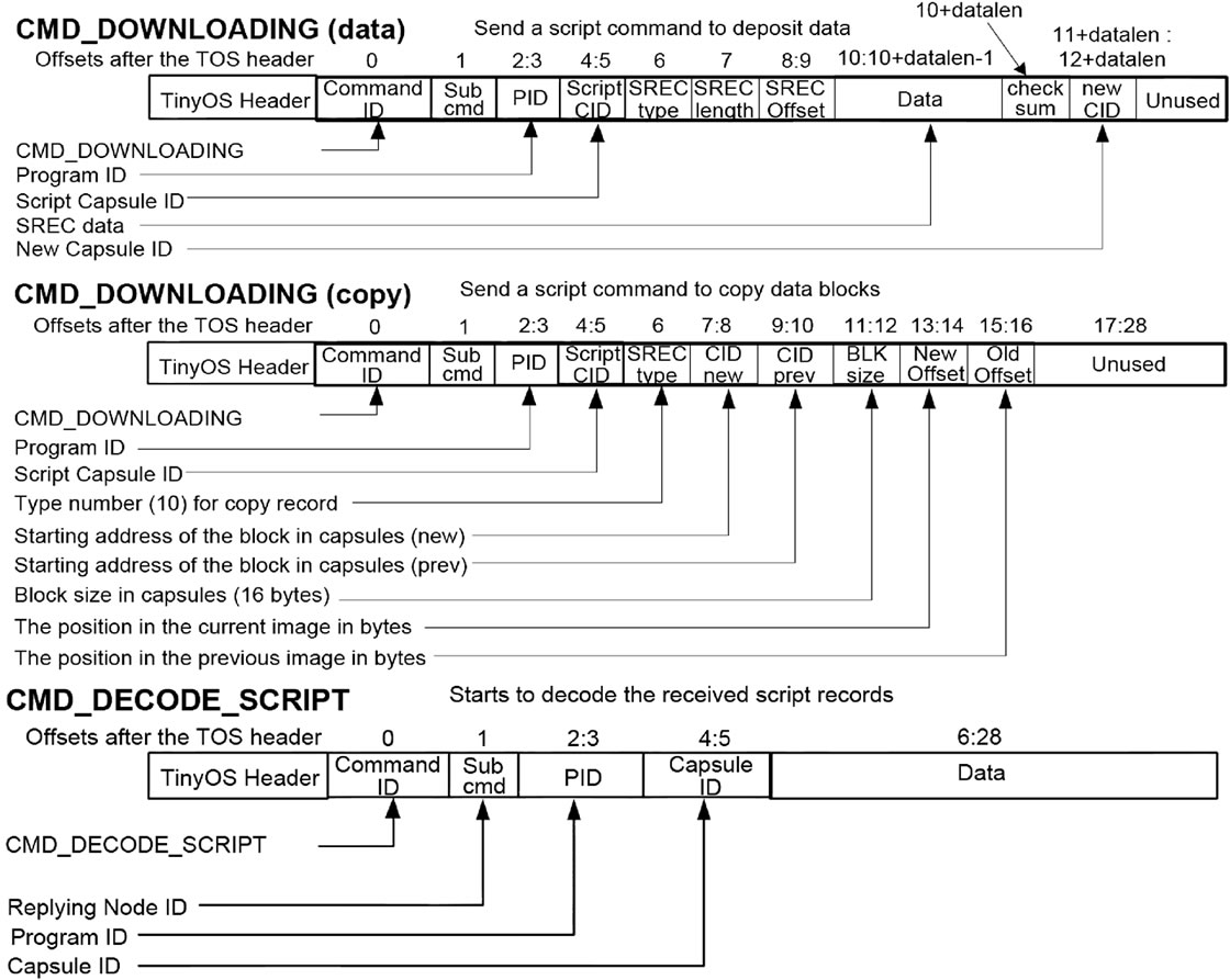
Figure 14. Message format for incremental network programming with Rsync difference generation and decode script.
 (a)
(a)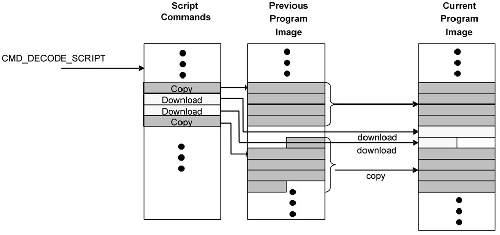 (b)
(b)
Figure 15. Steps for incremental network programming with Rsync difference generation and decode script.
Message CMD_DOWNLOADING (data) has almost the same format as a normal data record download message except for the script CID and new CID fields. The script CID field is the sequence number of the command within the script and the new CID field is the location where the data record embedded in the command will be copied for building the program image.
Message CMD_DOWNLOADING (copy) is also stored in a similar way as a normal data record. A copy command has the SREC type field. This is for the Motorola SREC type and only several values are allowed by the specification (0,1,2,3,5,7,8 and 9). We extended the meaning of this field so that the value 10 represents a copy record. This allows us to store a copy command in the same manner as other data records, but can still interpret the copy command correctly. Finally, message CMD_DECODE_SCRIPT makes the network programming module start decoding the downloaded script commands.
6.1.2. Storage Organization and Program Rebuild
As for the storage space for the script commands, we need to choose among RAM, internal flash memory and external flash memory. RAM would be better than the others for its fast access time. However, the size of a script can be as large as a list of download messages in the worst case. Since the largest program size is 128 KB, it may not fit into RAM (4 KB) or the internal flash memory (4 KB) when the program size is large. Thus, the script should be stored in the external flash memory.
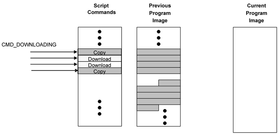
We divided the external flash memory into three sections: the previous program image, the current program image and the script sections.
At first, the host program sends the script as CMD_ DOWNLOADING messages. The sensor node stores these messages in the script section if it is in the incremental network programming state. This is shown in Figure 15(a). When the host program queries any missing script commands, the sensor node scans the script section. When the difference between the two program versions is small, the traversal of the script section can finish quickly. If the sensor node finds any missing record, it requests the retransmission of the record. Then, the host program sends the record again.
After receiving the decode command from the host program, the sensor node starts rebuilding the program code. This is shown in Figure 15(b). A download command is copied from the script section to the current program image section after the CID field is modified to the new CID value. As for a copy command, the sensor node starts copying SREC records from the previous program image to the current program image. A SREC record from the previous section is copied to the current program section after the CID and the byte offset fields are modified for the new values.
6.2. Results
Since a sensor node does not rebuild the program image until it receives all the script commands, we modified the metrics for the evaluation. We measured the transmission time and the decode time for the three cases. The host program saves the time stamp value when it sends a decode command and gets the next time stamp value when it receives the reply from the sensor node. The decode time is calculated as the difference of the two time stamp values. Table 8 shows the results.
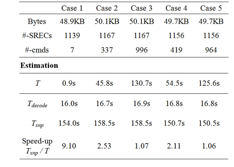
Table 8. Transmission time for incremental network programming with Rsync difference generation and decode script.
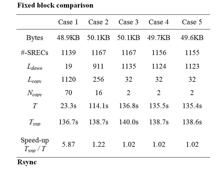
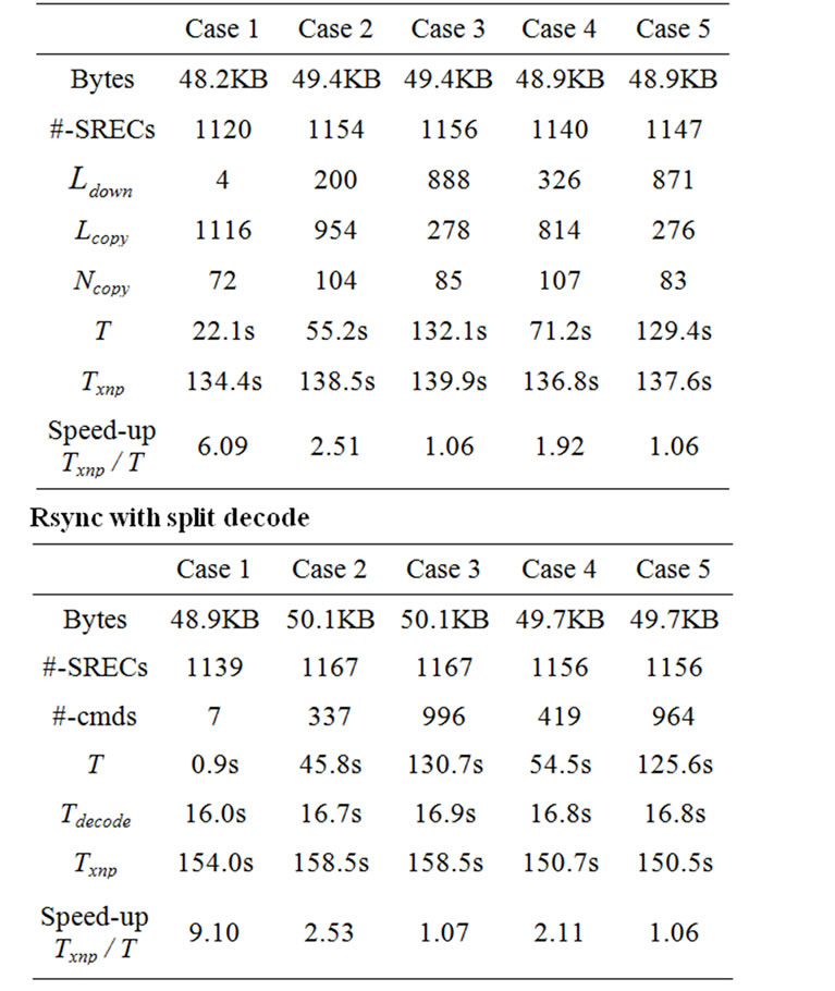
Table 9. Speed-up in programming time for three versions of incremental network programming.
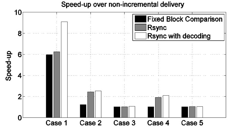
Figure 16. Speed-up in programming time for three versions of incremental network programming.
For Case 1, only 7 script messages were transmitted and this made the transmission time very small. The sum of transmission time and the decode time is 16.1s while non-incremental delivery took 154.0s. This gives a speed-up of 9.10. For Case 2, more script lines were transmitted (337 script messages for the 1167 line program code) and the speed-up over non-incremental delivery was 2.53. For Case 3, we sent an even larger number of script messages (996 messages for the 1167 line program code) and the speed-up was 1.07. When we modified the configuration file, we had a similar result as Section 5. For Case 4, 419 script messages for the 1156 line program code had a speed-up of 2.11 over nonincremental delivery. For Case 5, most of the SREC records were transmitted as download script commands (964 out of 1156) and the speed-up was 1.06.
Figure 16 and Table 9 show the results of the three incremental network programming implementations: Fixed Block Comparison, Rsync and Rsync with split decode. We can find that splitting the script transmission and the program rebuild improves the overall programming time. When the source code is modified at minimum, the implementation with Rsync and split decode saved programming time by sending fewer script messages even though it has to decode the script messages. When a small number of source code lines were added, the programming time was a little better than the implementation that just uses the Rsync algorithm. For the major program change, it didn’t achieve the speed-up, but it was still as good as non-incremental delivery.
We can comment on Case 3. Even though we used the Rsync algorithm and split decode, the speed-up over non-incremental delivery was negligible. This is because the difference between the two program images cannot be described with a small number of insert, copy and skip operations.
7. Conclusions
Network programming is a way of programming wireless sensor nodes by sending the program code over radio packets. By sending program code packets to multiple sensor nodes with a single transfer, network programming saves the programming efforts for a large sensor network. The network programming implementation in TinyOS releases 1.1 or later provides the basic capability of network programming – delivering the program code to the sensor nodes remotely. However, the network programming implementation is not optimized when part of the program code has changed. It transmits all the code bytes even though the new version of program code is only slightly different.
We extended the network programming implementation so that it reduces programming time by transmitting an incremental update rather than the entire program code. The host program generates the difference of the two program images using the Rsync algorithm and transmits the difference to the sensor nodes. Then, the sensor nodes decode the difference script and build the program image based on the previous program version and the difference script. We tested our incremental network programming implementation with some test applications. We have a speed-up of 9.1 for changing a constant and 2.1 to 2.5 for changing a few lines of code in the source code.
For future work, we plan to extend our incremental network programming for multihop delivery. One way is to use an existing multihop network programming mechanism such as Deluge [6] or MOAP [5]. In this case, we need to modify the underlying multihop delivery mechanism to be compatible with an incremental program image as well as non-incremental image. Another way is to use a generic multihop routing protocol. Since a generic routing protocol just delivers packets without storing the program image, our incremental network programmig mechanism can be easily extended for multihop delivery by replacing a single-hop send command with a multihop version.
8. Acknowledgements
Thanks to Crossbow Technology for providing the source code for the network programming module and the boot loader. This work is was supported by the Defense Advanced Research Projects Agency under a contract F33615-01-C1895 (“NEST”), the National Science Foundation under grants #0435454 (“NeTS-NR”) and #0454432 (“CNS-CRI”), a grant from the Keck Foundation, and generous gifts from HP and Intel.
9. References
[1] J. Jeong, S. Kim, and A. Broad, “Network reprogramming,” http://webs.cs.berkeley.edu/tos/tinyos-1.x/doc/Net -workReprogramming.pdf., 2003.
[2] Crossbow Technology. Mote in network programming user reference, http://webs.cs.berkeley.edu/tos/tinyos-1.x/ doc/Xnp.pdf., 2003.
[3] A. Tridgell, “Efficient algorithms for sorting and synchronization. PhD thesis,” Australian National University, Canberra, Australia, February 1999.
[4] A. Atmega, 128 microcontroller reference, http://www. atmel.com/dyn/resources/prod_documents/doc2467.pdf.
[5] T. Stathopoulos, J. Heidemann, and D. Estrin, “A remote code update mechanism for wireless sensor networks, cens technical report #30,” http://lecs.cs.ucla.edu/ thanos/ moap-TR.pdf., 2003.
[6] J. W. Hui and D. Culler, “The dynamic behavior of a data dissemination protocol for network programming at scale,” pp. 81–94, November 2004.
[7] P. Levis, N. Lee, M. Welsh, and D. Culler, “Tossim: Accurate and scalable simulation of entire tinyos applications,” The First ACM Conference on Embedded Networked Sensor Systems (Sensys’03), 2003.
[8] N. Reijers and K. Langendoen, “Efficient code distribution in wireless sensor networks,” in Proceedings of the 2nd ACM International Conference on Wireless Sensor Networks and Applications (WSNA’03), pp. 60–67, September 2003.
[9] R. Kapur, T. Yeh, and U. Lahoti, “Differential wireless reprogramming of sensor networks, ucla cs213 project report,” 2003.
[10] T. Yeh, H. Yamamoto, and T. Stathopolous, “Over-theair reprogramming of wireless sensor nodes, ucla ee202a project report, http://www.cs.ucla.edu/˜tomyeh/ee202a/ project/EE202a_final_writeup.doc., 2003.
[11] P. Levis and D. C. Maté, “A tiny virtual machine for sensor networks,” Proceedings of the 10th International Conference on Architectural Support for Programming Languages and Operating Systems (ASPLOS’02), pp. 85–95, October 2002.
[12] P. Levis, N. Patel, S. Shenker, and D. Culler, “Trickle: A self-regulating algorithm for code propagation and maintenance in wireless sensor networks,” in Proceedings of the 1st Conference on Symposium on Networked Systems Design and Implementation (NSDI’04), pp. 2, March 2004.
[13] W. Emmerich, C. Mascolo, and A. Finkelstein, in Proceedings of the 22nd International Conference on Software Engineering, June 2000.
[14] A. Muthitacharoen, B. Chen, and D. Mazi´eres, “A low -bandwidth network file system,” pp. 174–187, October 2001.
[15] G. H. Flammer, “Method for distributing program code to intelligent nodes in a wireless mesh data communication network,” US Patent 5,903,566, May 1999.
[16] C. M. Jarsync, “A java implementation of the rsync algorithm,” http://jarsync.sourceforge.net/.
Appendix
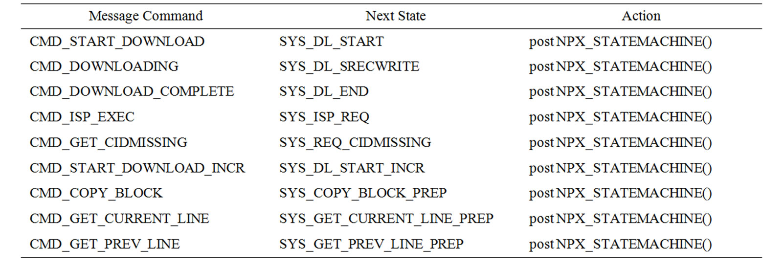
Table 10. Receiving the incoming message.
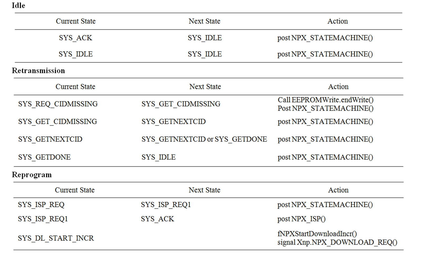
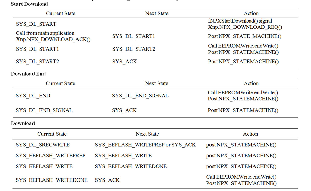
Table 11. NPX_STATEMACHINE() state transision.
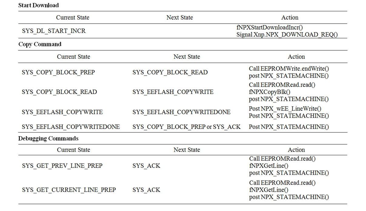
Table 12. NPX_STATEMACHINE() state transition (added for incremental network programming).
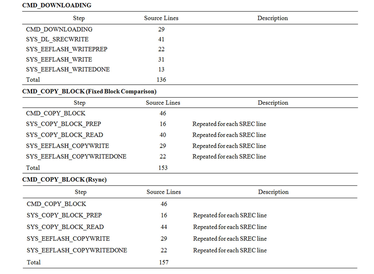
Table 13. Cost of message handling.