Materials Sciences and Applications
Vol.4 No.12(2013), Article ID:41552,7 pages DOI:10.4236/msa.2013.412109
Distribution of Electromagnetic Force of Square Working Coil for High-Speed Magnetic Pulse Welding Using FEM
![]()
Environmentally Materials & Components Center, KITECH, Jeonju-si, Korea.
Email: shimjy@kitech.re.kr, *kanbo@kitech.re.kr
Copyright © 2013 Ji-Yeon Shim, Bong-Yong Kang. This is an open access article distributed under the Creative Commons Attribution License, which permits unrestricted use, distribution, and reproduction in any medium, provided the original work is properly cited.
Received September 10, 2013; revised October 21, 2013; accepted November 18, 2013
Keywords: Magnetic Pulse Welding; Working Coil; Electromagnetic FE-Model
ABSTRACT
Magnetic pulse welding process, one of high speed welding processes, uses electromagnetic force from discharged current through a working coil which develops a repulsive force between the induced currents flowing parallel and in the opposite direction in the pipe to be welded. For achieving the successful weldment and using this process, the design of working coil is the most important factor, because working coil has to generate a high-intensity magnetic field on the surface of the workpiece during the process. Therefore, the objective of this study is to analyze the distribution of electromagnetic force of square working coil for magnetic pulse welding. For this, FE-model has been developed to analyze the distribution of electromagnetic force; after that, distribution of electromagnetic force, results of numerical analysis and experimental results for verifying the developed FE-model were compared. A 3-dimensional electromagnetic FE-model has been developed using a general commercial computer program, ANSYS/EMAG code. The shape and material of square working coil were decided through literature surveys. For the experiment, an MPW equipment W-MPW manufactured by WELDMATE Co., Ltd. was employed; also the materials were the Al 1070, SM45C for Al and Steel square pipe and rod respectively. After the experiment, leakage test was used to verify the weldability. Also weld joints were observed on longitudinal cross-section by microscope. The electromagnetic force generated was the greatest one at the center adjacent to square working coil, decreasing as moving into the edge. As the result of Al/Steel welding experiment, weldment of square Al pipe was not completed at the corner of weldment. These results are similar to the output data from developed electromagnetic FE-model where electromagnetic force decreases as moving into the corners of square working coil.
1. Introduction
The car industry is currently working to accommodate the conflicting requirements of both environmental legislation and customer demands for high performance and safety by developing a light-weight vehicle [1]. So the light weight materials such as aluminum and magnesium have been applied in automation. Especially, development of aluminum space frame for automotive body structure has been carried out in recent years [2]. However, when only light materials are used in automotive body structure, they cannot satisfy the required intensity and strong property, and it is imperative to weld light weight materials with existing used ones. Accordingly, it has been required to study on welding of dissimilar metals [1] due to the different physical properties between materials. Welding as existing fusion welding generally causes not only defects, such as solidification, cracking, porosity and oxidation, but also transformation and corrosion. For this reason, more attention has been paid to magnetic pulse welding process as a kind of solid-state welding these days.
In the magnetic pulse welding process, welding is achieved by the pressure for outer workpiece that only uses the electromagnetic force which takes advantage of Fleming’s left-hand rule. The electrical energy stored in the magnetic pulse power source is discharged instantaneously as a high current to the working coil by a trigger discharge, and thus an induced current is generated at the conductive outer workpiece positioned within the working coil. For successful magnetic pulse welding, it is important to develop a working coil that can gain enough electromagnetic force for welding.
This process is a complicated research area involving different aspects including electro-magnetic, mechanics, thermal, and material science. The extensive knowledge in this complicated area is not easily obtained, as the variety of experimental setups and the complicated dynamic interaction between different phenomena in the welding process are extremely difficult to describe in a closed analytical form. Therefore, computer modeling of the welding process is a useful approach for better insight into dynamic deformation mechanics with electro-magnetic field interaction, and further it provides design and quality control information.
Research on the working coil of the magnetic pulse welding is concentrated on the foundation of the theoretical analysis of electromagnetic forming [3,4]. Li et al. [4] presented a numerical simulation of the magnetic pressure in tubular working coil. Also Zhang [3] analyzed the shape and material of the single and multi turn solenoid coil with finite element method. Takatsu et al. [5] formulated a mathematical model to solve the problem of forming of a circular disk interacting with a pancake coil. The assumed axisymmetry of the problem along with other simplifying assumptions, has been used to obtain a set of partial differential equations for the magnetic field, mechanical displacement, and the current in the coil [6,7]. CALE code was employed by Fenton and Daehn [8].
As mentioned above, the study on tubular structure working coil has usually been reported, but the one on the square working coil has never been reported. Consequently, the objective of this research is to develop FEmodel for square working coil in magnetic pulse welding which is a basic research for manufacturing the automotive space frame. For this study, first, the shape and material of coil were decided through literature survey. Second, a 3-dimensional electro-magnetic FE-model for electromagnetic phenomenon of square working coil by using the ANSYS/EMAG software has been developed. The comparison between the calculated and measured results was finally done to verify the developed electromagnetic FE-model.
2. Development of Square Working Coil
2.1. Magnetic Pulse Welding
The magnetic pulse welding is a solid-state, cold-welding process that is accomplished when a magnetic pulse causing a high-velocity impact between two materials, resulting in a true metallurgical bond [8]. The technology is principally similar to explosion welding. The principle of magnetic pulse welding is based on the physical phenomena of magnetic fields induced by an electric current [9]. It is well known that two conductors with their electric currents travelling in opposite direction repels due to the interaction of their oppositely orientated magnetic fields induced. Figure 1 shows in the initial coil, the inductor, a current impulse which in turn, generates a current of the opposite direction in the outer workpiece. A electromagnetic force to the initial coil causes the outer workpiece to impact at a tremendous force and speed at the inner workpiece, resembling an explosion taking about 20 millionths of a second [7].
The magnetic pulse welding system consists of magnetic pulse power source for charging extreme energy and working coil for discharging it. To generate the high-current impulse an arrangement of capacitors, an arrestor-discharge and a working coil has been constituted the core of the magnetic pulse module, as shown in Figure 2 [10,11]. The capacitors, special high-voltage capacitors with extremely low self-inductance, can store charge up to a certain maximum level that is determined by the arrestor-discharge, which creates a short, highcurrent pulse in the work coil [6].
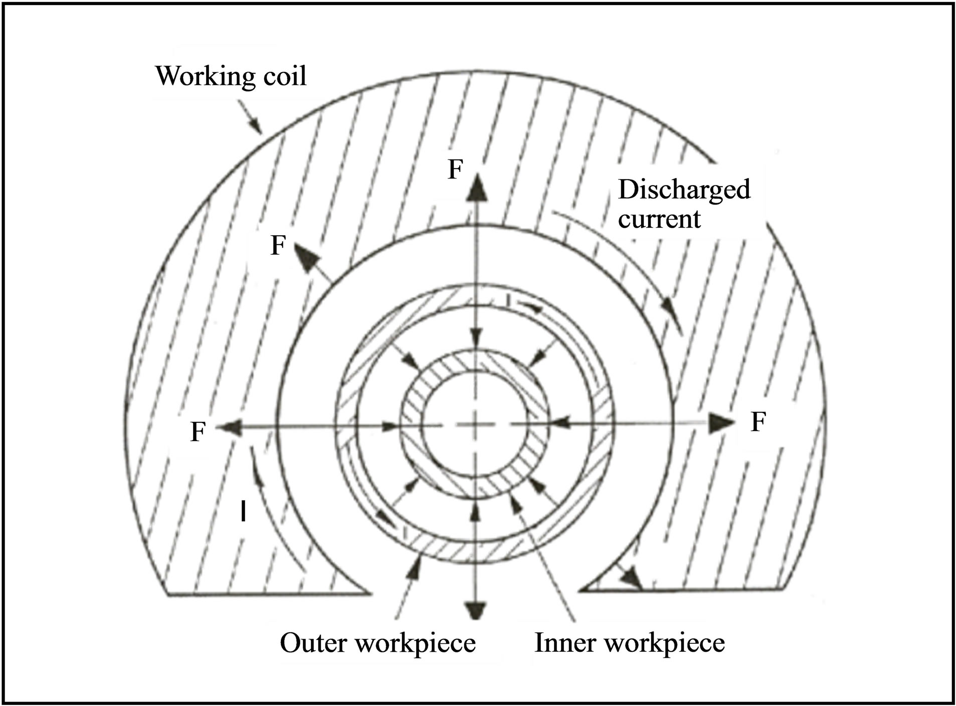
Figure 1. The principle of the magnetic pulse welding process [7].
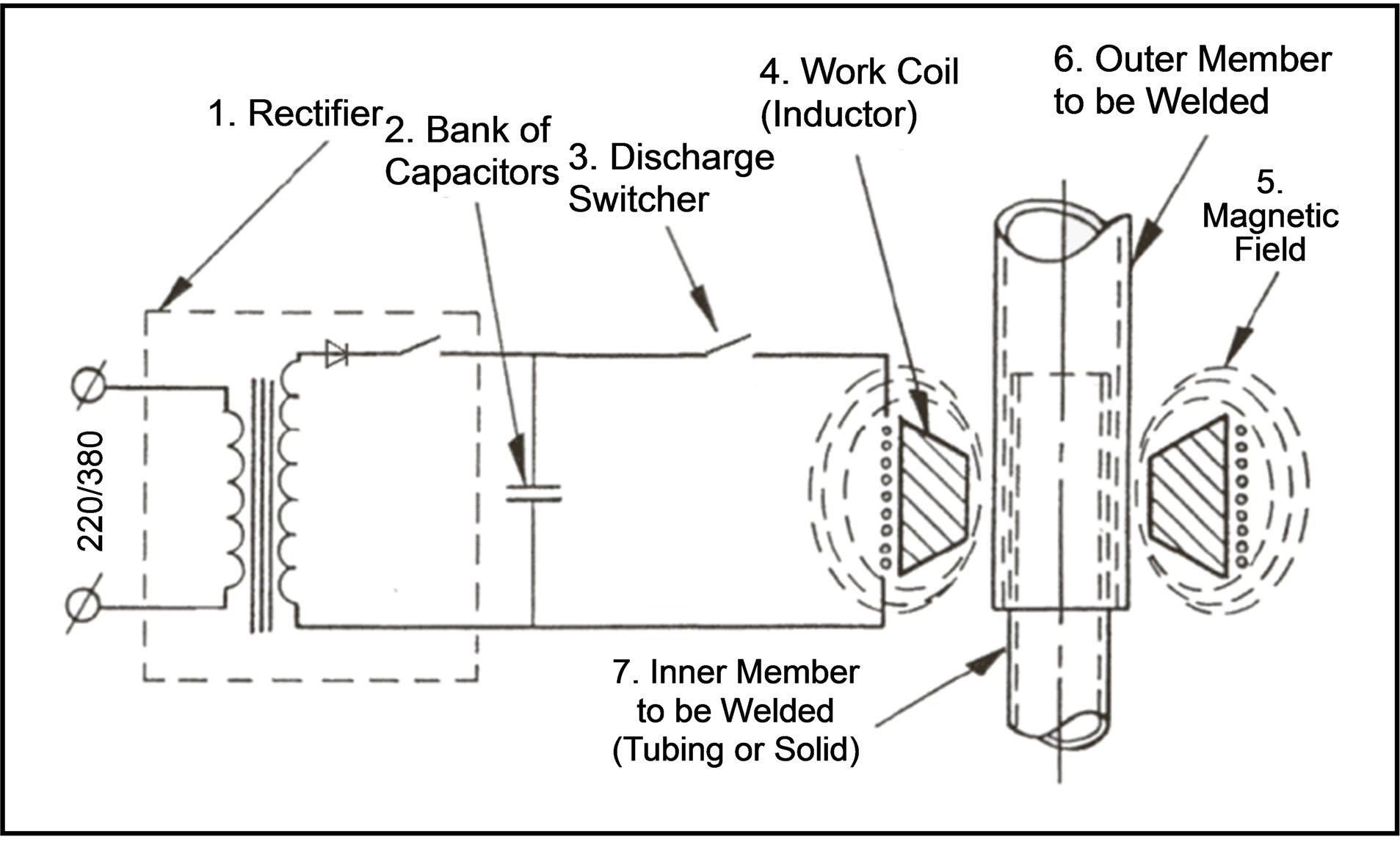
Figure 2. The system of magnetic pulse welding [11].
2.2. Shape and Material
As I mentioned before, magnetic pulse welding uses the electromagnetic force from current discharged through the working coil which develops a repulsive force between the induced currents flowing parallel and in the opposite direction in the workpice to be welded. However, the theoretical analysis for development of perfected working coils considering various factors hasn’t been established yet. Nevertheless generally the considered factors were classified into a shape and an electric property [10]. Therefore firstly, the shape considering a welding direction according to application is decided. Second, distribution an electromagnetic force by the interaction between working coil and outer pipe should be investigated after selecting materials that electric resistance is low and that has enough intensity mass possible to resist electromagnetic force on processing.
The shapes of working coil used in welding are generally classified into a compression coil, an expansion coil and a plate coil. A compression coil is the solenoid type surrounding processed materials which is welded from outside direction to inside. Expansion coil is inserted inside processed materials and welded from inside to outside. A plate coil which located on and under the processed material was employed in plate welding [3]. Therefore, the shape of solenoid-typed compression coil was chosen between compression coil and expansion one that are used in joining of pipes because it is located in the outside of the specimens. In addition it has no size limit as well as simple connection magnetic pulse power source.
The material of working coil should allow for an electric feature such as conductivity to prevent the damage of condenser by duration of magnetic field or sudden discharge. Therefore, copper, aluminum and berylliumcopper, as shown in Table 1 have been considered and selected the beryllium-copper for this study. Figure 3 shows the developed square working coil.
3. Numerical Analysis
3.1. Analysis Method and Procedure
After shape and material of coil was chosen, electromagnetic force needed to welding should be confirmed. However, there is a limitation for electromagnetic force

Table 1. Mechanical and electrical properties.

Figure 3. Square working coil for this study.
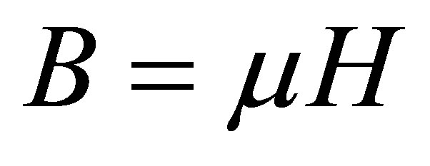
used for welding to be studied. Because this force is decided by interactions of electromagnetic and workpiece model development of numerical analysis can be a useful means. The electromagnetic force P is expressed the following formula (1) [12-13]. B is magnetic flux density, H is magnetic field intensity and u is permeability.
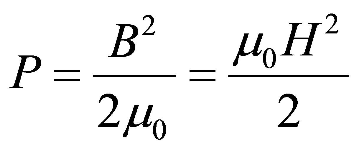 (1)
(1)
Development of empirical model for a magnetic pulse welding process is described by the fundamental Maxwell equations [5]. The magnetic field of the workpiece is expressed from Equations (2) to (5).
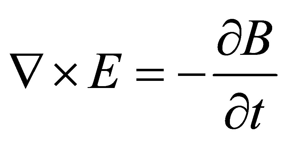 (2)
(2)
 (3)
(3)
 (4)
(4)
 (5)
(5)
where E is the electric field intensity and J is the electric current density. To these differential relations, the constitutive relations are included from Equations (6) and (7). Where m is the permeability and s is the conductivity.
 (6)
(6)
 (7)
(7)
As the workpiece is treated as a single turn square coil, the boundary conditions can be assumed as follows [5]. To these differential relations, the constitutive relations are included.
In the Cartesian coordinate system, not only B (magnetic induction intensity) is perpendicular to x axis at y = 0, but also A (vector magnetic potential) is equal to zero at x = 0.
 (8)
(8)
where m is the permeability of the conductor, s is electrical conductivity of the conductor material, and 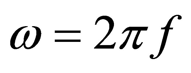 is angular frequency of the current.
The skin depth effect is an important factor in high frequency conductors. When a high frequency current flows through a conductor, the current tends to flow on the conductor surface. The magnitude of the current is exponentially decreased with the depth of penetration into the conductor. The depth at which the value of the current decreases to 1/e (≒37%) of the surface current is defined as skin depth and expressed the following [5]:
The numerical analysis has been done through ANSYS/EMAG that a general electromagnetic mechanics computer program. Figure 4 shows a schematic diagram for magnetic pulse welding this study.
The 3D axisymmetirc model for a coil to outer pipe interaction was chosen numerical calculations for working coil and outer pipe were performed for Beryllium Copper and Al respectively. Table 2 shows the material properties for working coil and outer pipe. Current was inputted into the working coil as a sine wave function. Not only the magnitude was 500 kA a, but also the frequency was 25 kHz for the experiment. To avoid the calculation complexity of energy transformation, current was employed as the excitation in the present analysis. Eight-node quadrilateral elements of mapped mesh with 219,605 nodes and 139,821 quadrilateral elements in total were employed.

Figure 4. A schematic diagram for magnetic pulse welding.
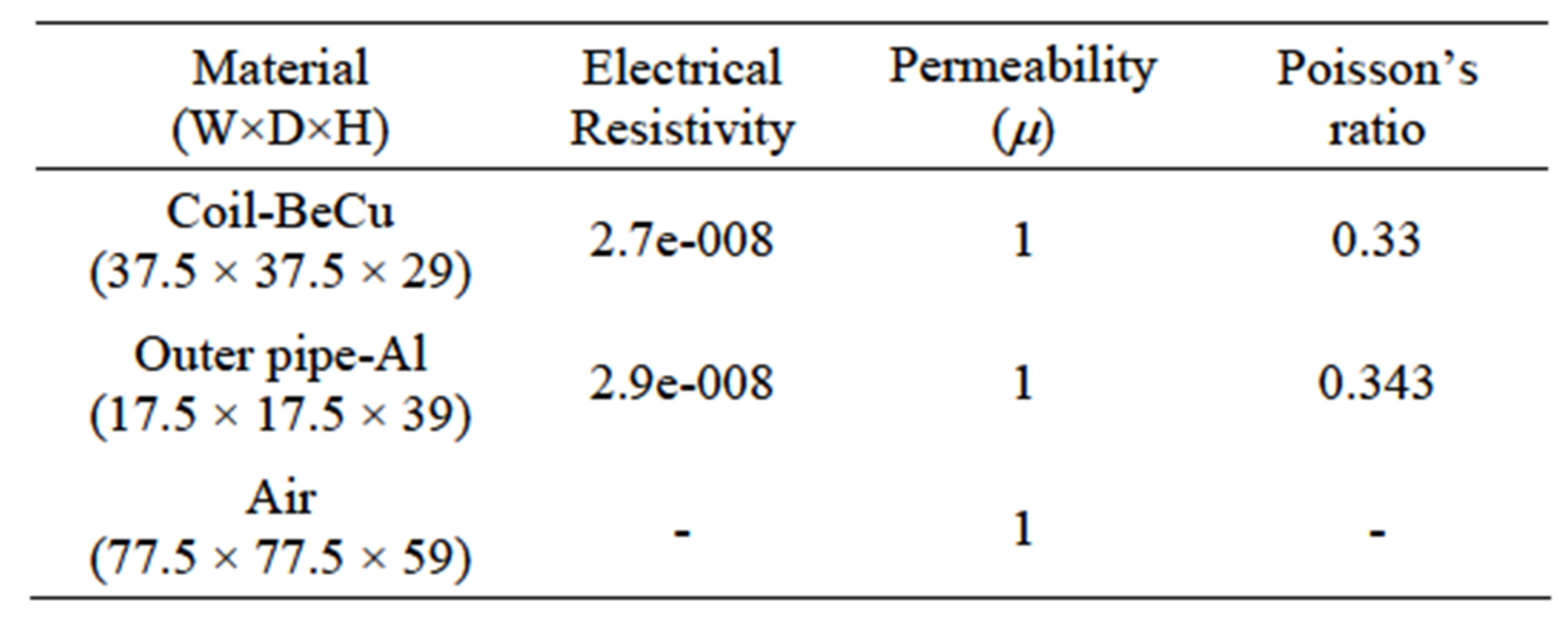
Table 2. Material properties for analysis.
3.2. Results and Discussion
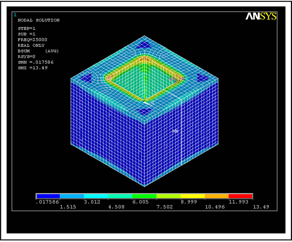
Figure 5 shows distributions of the magnetic flux density of the square working coil. Magnetic flux is increased at the upper part of a coil and concentrated in adjacent corner of coil.
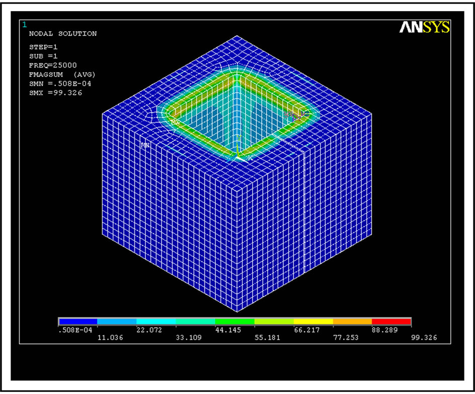
Figures 6(a)-(b) represent the distributions of the electromagnetic force of the square working coil. Especially, Figure 6(c) indicates the distribution of the electromagnetic force of inside square coil. The maximum electromagnetic force generated in coil is about 951 N and in the edge about 503 N was measured. When interaction between a square coil and Al pipe is being processed, the collision of Al pipe is caused because the electromagnetic force acts from surface to inside of the Al pipe.
As a result, the magnetic flux density and electromagnetic force generated was the greatest at the center adjacent to coil, decreasing as moving into the edge. These phenomena occurred because current is accumulated in the corner of the square coil compared with the solenoid coil at discharging of current.
4. Experimental Works
4.1. Setup and Procedure
To test for the developed working coil efficiency test, as show in Figure 7, the experimental employed in this study is a W-MPW manufactured by WELMATE CO., LTD.
Table 3 presents the specification for this equipment that has the maximum charging energy 36 kJ. Additionally, in order to observe a discharge waveform, Rogowski coil was installed in working coil. [14-17]
Figure 8 represents the outer workpiece (Al) and inner workpiece(Steel) within working coil were inserted, and welding conditions as shown in Table 4. Outer pipes of 2mm in thickness and 110 mm in length were machined from industrial pure aluminium bars of Al1070. Their outer diameter was 30 mm for straight. And inner rod was employed the S45C as shown Table 4.

Table 3. Specifications of MPW equipment.
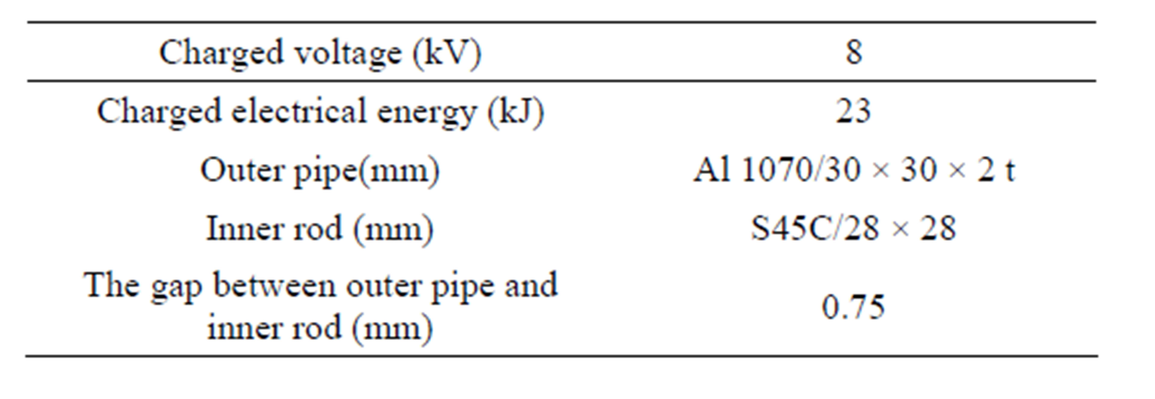
Table 4. Welding condition.
 (a)
(a)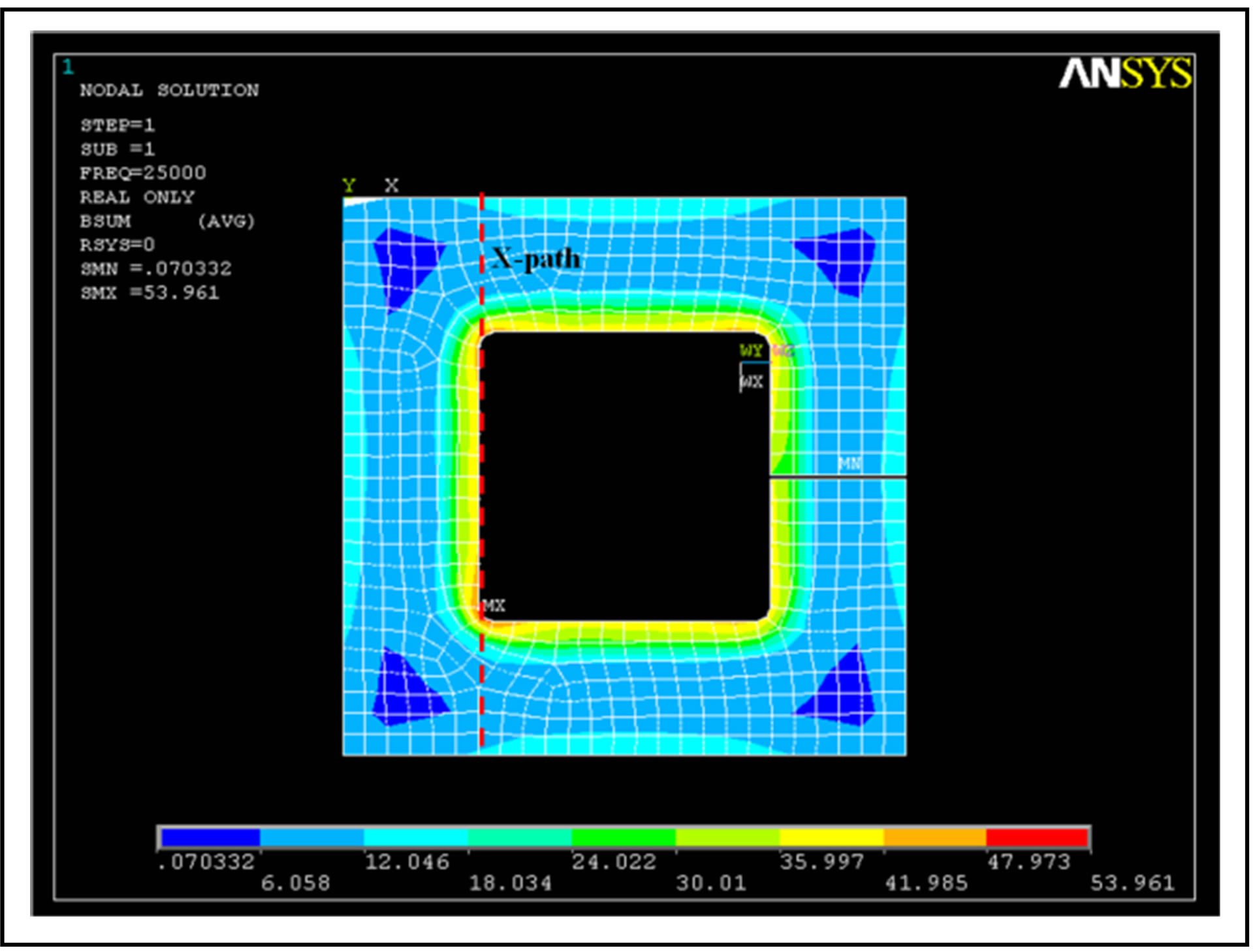 (b)
(b)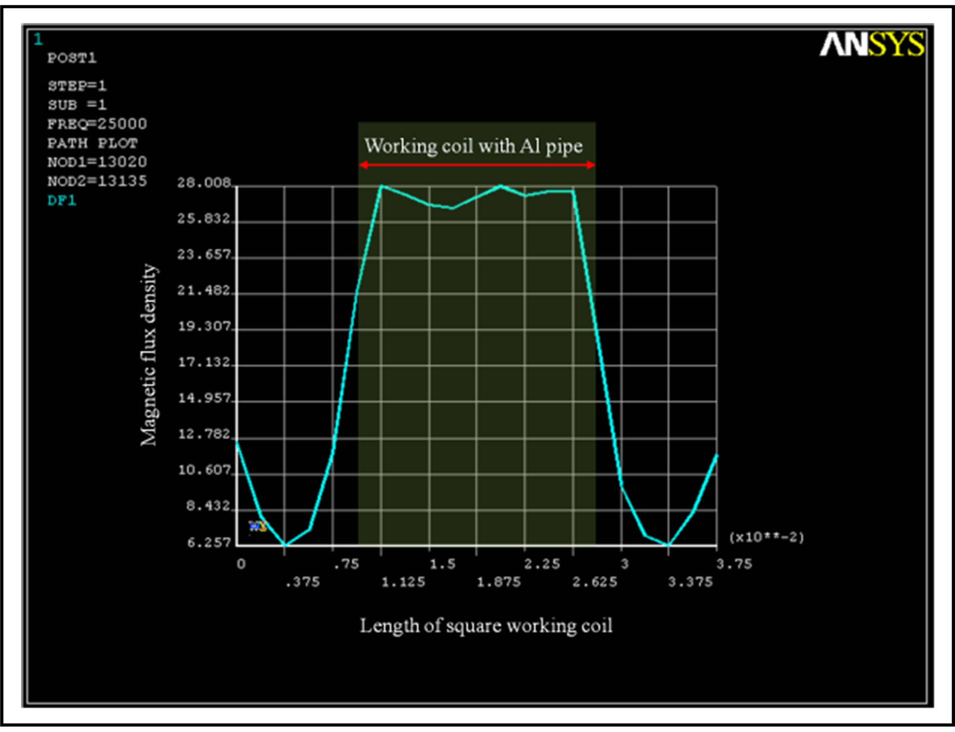 (c)
(c)
Figure 5. Distributions of the magnetic flux density. (a) Isometric view; (b) Top view; (c) Graph.
For magnetic pulse welding, the gap between Al pipe and Steel rod was 0.8 mm. After experimenting, the
 (a)
(a) (b)
(b)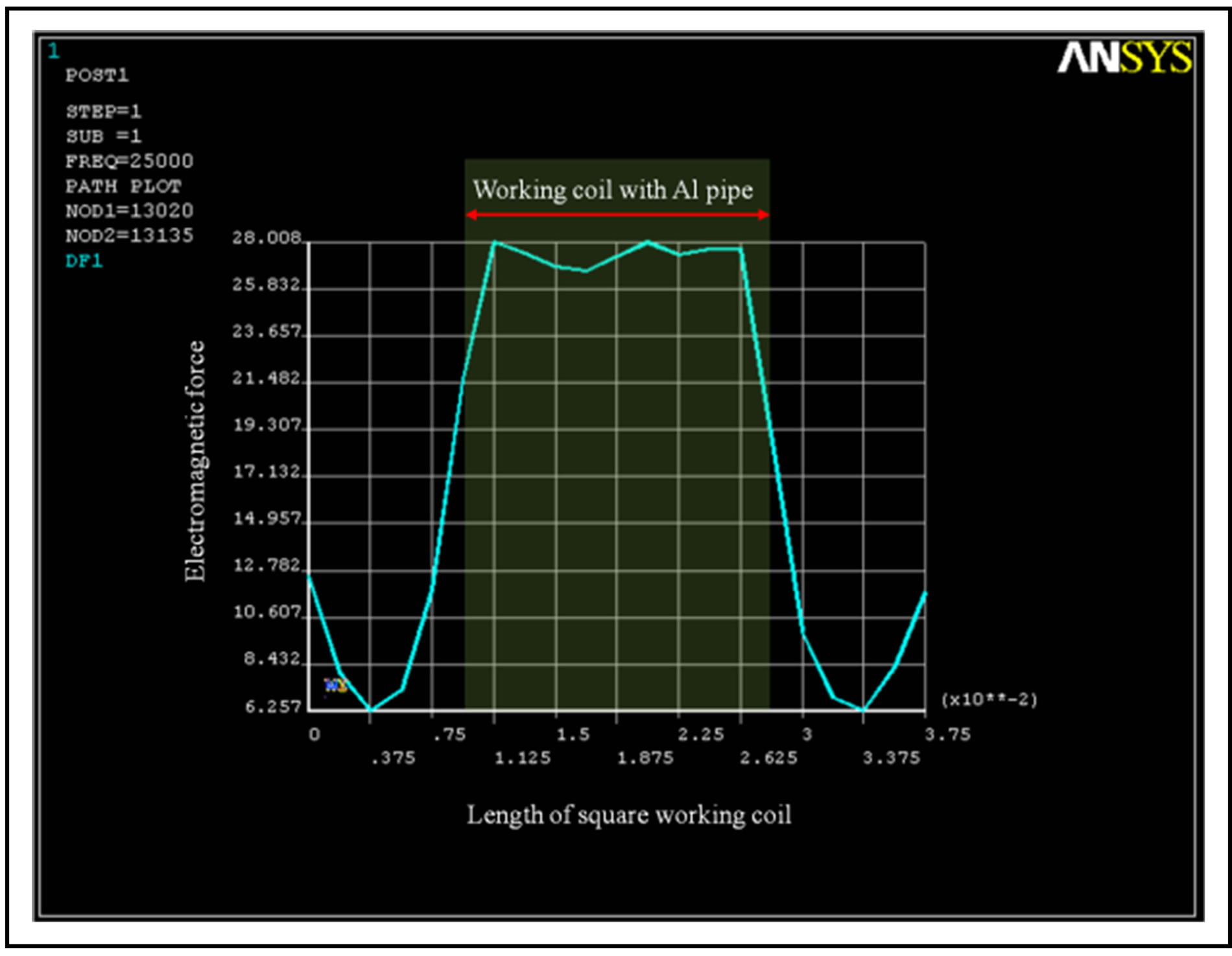 (c)
(c)
Figure 6. Distributions of the electromagnetic force. (a) Isometric view; (b) Top view; (c) Graph.
specimens were ground using emery paper (#400 ~ #1500) prior to welding to remove machine marks
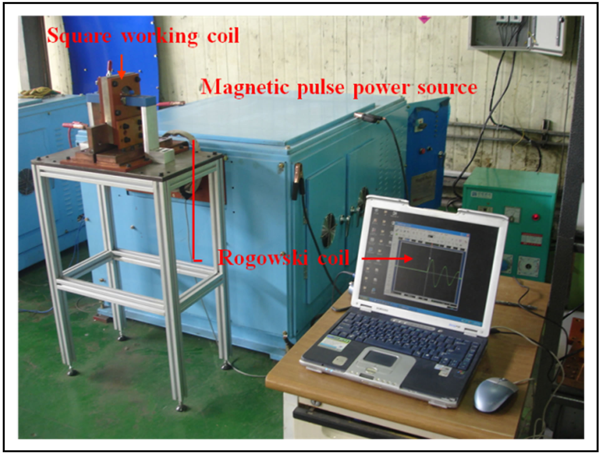
Figure 7. A schematic diagram for magnetic pulse welding.

Figure 8. A schematic diagram for experiment.
sustained during machining. In addition, ultrasonic cleansing was carried out for approximately 10 minutes within acetone in order to remove grease. And then the weldment was observed by microscopic on circumferential cross section.
4.2. Results and Discussion
Figure 9 shows the measured waveform while discharging the energy charged in working coil. The sin-waveform of decreasing vibration was recorded and it took about 25 us to peak current needed to welding. The weldment and section of welded part were presented at Figure 10. Peak current of about 8 kV was measured as 530 kA. In all sides, wave pattern was observed as Figure 11.
However, the wave pattern in the whole area didn’t measured, because welding was not completed at the corner of a square working coil. These results are similar to the output data from electromagnetic model that electromagnetic force decreases as moving into the corners as shown Figure 6.
5. Conclusions
1. The electromagnetic models for a square working
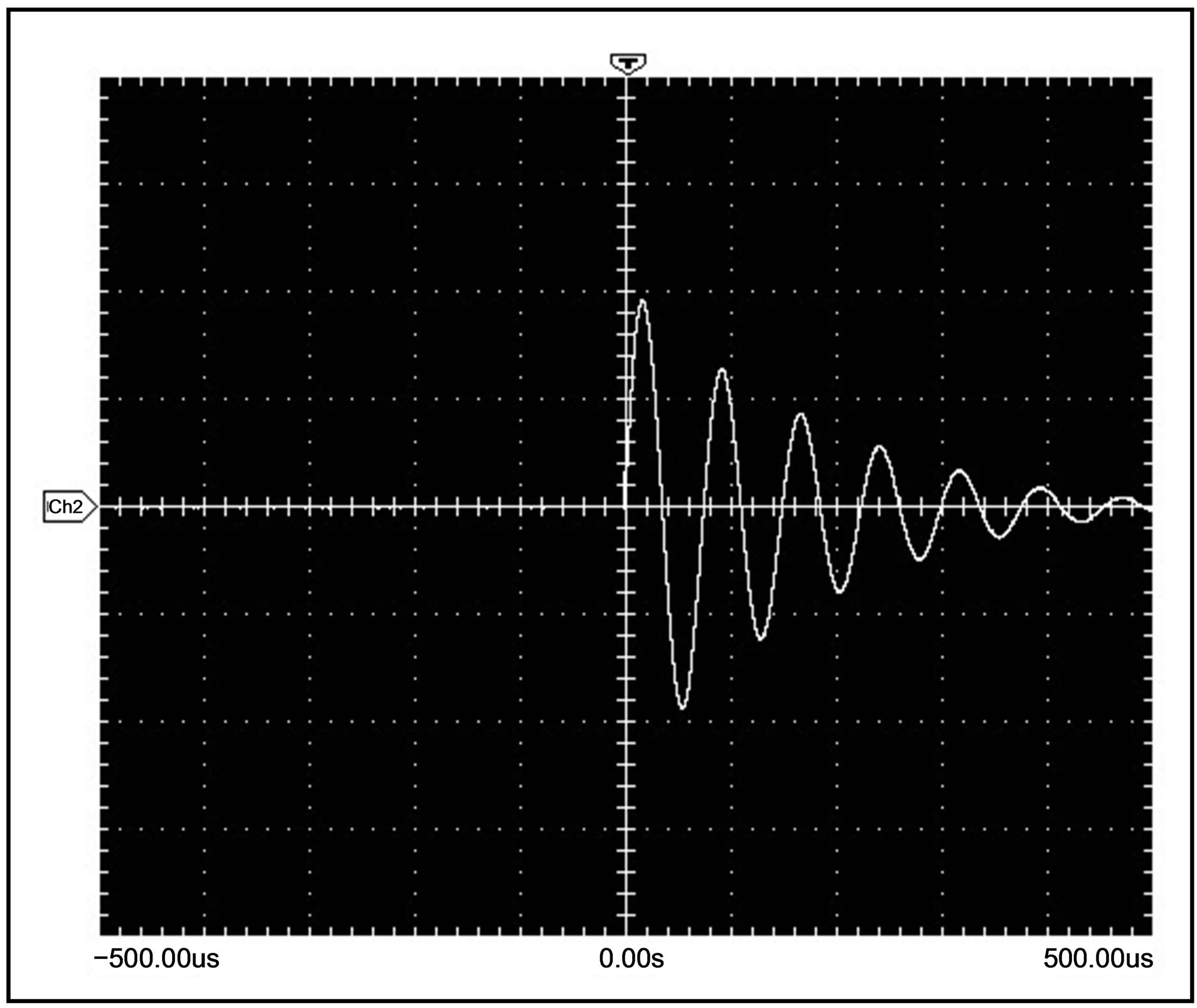
Figure 9. Discharge current waveform (15v/div, 100us/div).
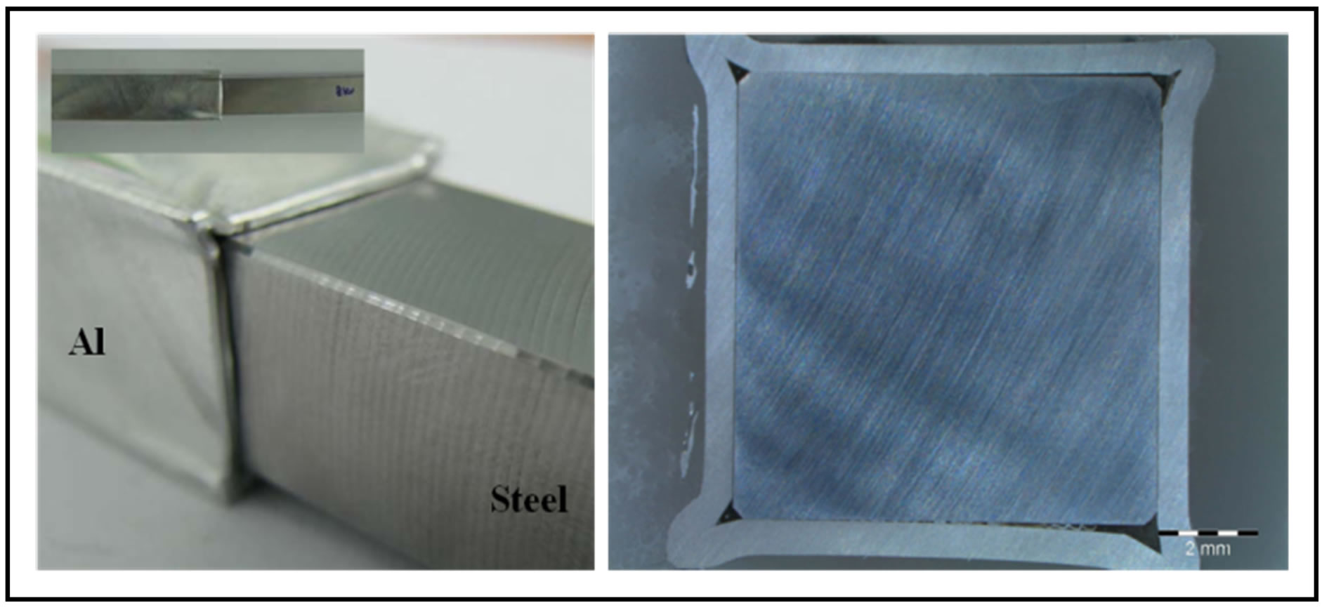
Figure 10. The section of weldment.
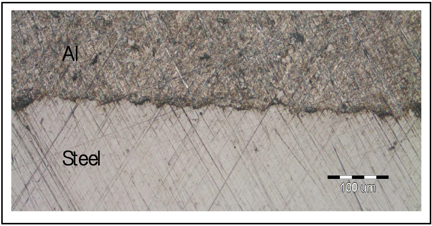
Figure 11. The macro cross-section of weldment.
coil have been developed to find the distributions of electromagnetic force. The developed models were verified with the comparison of the result data of the experiments.
2. The maximum electromagnetic force generated in coil is about 951 N and in the edge about 503 N was measured. The generated electromagnetic force is the greatest at the centre adjacent to coil, decreasing as moving into the edge.
3. The sin-waveform of decreasing vibration was measured with a period of 25 μs while discharging the energy charged in working coil. The welding at the corners was not completed, so it might be required to study the suitable knowledge and technology for a square working coil.
REFERENCES
- Y. B. Park, “Design of Joints for the Automotive Space frame with Electromagnetic Forming and Adhesive Bonding,” Ph.D. Thesis, Graduate School of the Seoul National University, Seoul, 2004
- K. Ito and H. Kobayashi, “Production and Fabrication Technology Development of Aluminium Useful for Automobile Lightweights,” Advanced Engineering Materials, Vol. 8, No. 9, 2006, pp. 828-835. http://dx.doi.org/10.1002/adem.200600072
- P. Zhang, “Joining Enabled by High Velocity Deformation,” Ph.D. Thesis, Ohio State University, Columbus, 2003.
- C. Li, Z. Zhao, J. Li, Y. Wang, and Y. Yang, “Numerical Simulation of the Magnetic Pressure in tube Electromagnetic Bulging,” Journal of Materials Processing Technology, Vol. 123, No. 2, 2002, pp. 225-228. http://dx.doi.org/10.1016/S0924-0136(02)00063-8
- N. Takatsu, M. Kato and K. Sato, “High-Speed Forming of Metal Sheets by Electromagnetic Force,” JSME International Journal, Vol. 31, No., 1988, pp. 142-148.
- A.E. Azab, M. Garnkich and A. Kapoor, “Modeling of the Electromagnetic Forming of Sheet Metals: State of the Art and Future Need,” JSME International Journal, Vol. 142, No. 1, 2003, pp. 744-754.
- D. Dudko, V. Chudakov, L. Kistersky and T. Barber “Magnetic Pulse Welding of Tubing: Exploring the Cold Welding Process,” Fabricator, Vol. 26, No. 8, 1996, pp. 62-66.
- G. K. Fenton and G. S. Daehn, “Modeling of Electromagnetically Formed Sheet Metal,” Journal of Materials Processing Technology, Vol. 75, No. 1-3, 1998, pp. 6-16.
- A. Kochan, “Magnetic Pulse Welding Shows Potential for Automotive Applications,” Assembly Automation, Vol. 20, No. 2, 2000, pp. 129-132. http://dx.doi.org/10.1108/01445150010321742
- J. S. Lee, “Electro-Magnetic Forming,” KSME, Vol. 28, No. 5, 1998, pp. 476-486.
- H. Hokari, T. Sato, K. Kawauchi and A. Muto, “Magnetic Impulse Welding of Aluminium Tube and Copper Tube with Various Core Materials,” Journal of Japan welding Society, Vol. 15, No. 4, 1998, pp. 615-622.
- V. Shribman, Y. Livschitz and O. Gafri, “The Application of Magnetic Pulse welding in the Automotive Industry,” Proceedings of the Global Powertrain Congress on Advanced Transmission Design & Performance, Vol. 34, 2005, pp. 21-27.
- Y. Haiping, L. Chunfeng and D. Jianghua, “Sequential Coupling Simulation for Electromagnetic-Mechanical Tube Compression by Finite Element Analysis,” Journal of Materials Processing Technology, Vol. 209, No. 2, 2008, pp. 1-7.
- J. Y. Shim, B.Y. Kang, M. J. Kang, I. S. Kim, D. H. Park and I. J. Kim, “A Study on the Development of FE-Model for Square Working Coil in Mangnetic Pulse Welding,” Proceedings of ICPVT-12, Jeju Island, 20-23 September 2009, p. 187.
- J. Y. Shim, B. Y. Kang, I. S. Kim, J. H. Lee and I. J. Kim, “Development of FE-Model for Al 5053 Sheet Plate Forming Using Electromagnetic Force,” Journal of Advanced Materials Research, Vol. 335-336, 2011, pp. 1099-1102. http://dx.doi.org/10.4028/www.scientific.net/AMR.335-336.1099
- J. Y. Shim, B. Y. Kang, I. S. Kim and D. H. Park, “Magnetic Pulse Forming of Thin-Aluminum Sheet Using Barforming Coil,” Journal of Advanced Materials Research, Vol. 335-336, 2011, pp. 621-624. http://dx.doi.org/10.4028/www.scientific.net/AMR.337.621
- H. G. Powers, “Bonding of Aluminium by the Capacitor Discharge Magnetic Forming Processes,” Welding Journal, Vol. 46, 1967, pp. 507-510.
NOTES
*Corresponding author.

