Journal of Modern Physics
Vol.2 No.11(2011), Article ID:8640,3 pages DOI:10.4236/jmp.2011.211166
Transparency of a Dielectric with Current Conductive Coating to Microwave Radiation
D.S. Rozhdestvensky Optical Society of Russia, St. Petersburg, Russia
E-mail: sidor@opten.ru
Received August 5, 2011; revised September 13, 2011; accepted September 27, 2011
Keywords: Wireless Communications, Radio Transparency, Tinted Window Glass
ABSTRACT
An attractive solution for microwave communication technologies is to place a transmit/receive antenna indoors, behind a window. In this case significant costs associated with rooftop rights, raiser and other inbuilding wiring may be avoided. While uncoated window glass introduces relatively small excessive loss into the propagation path, the situation is quite different with coated, “tinted” or laminated glass, which is frequently used to improve thermal and illumination conditions behind it. Insertion loss of such a window glass may be up to 30 dB, depending on type of a glass, carrier frequency, and angle of incidence of the radiation beam. We experimentally demonstrated a possibility of making windows covered by conductive coatings transparent for electromagnetic radiation. This has been achieved by removing a small share of the coating to the effect that non-conducting parts of the window surface split the conductive coating into areas narrow compared to the electromagnetic radiation wavelength.
1. Introduction
Indoor installation of transmit/receive microwave antennas requires high transparency of the window glass at operation frequencies, which for high-bit-rate applications should be selected from the short centimeter-wave or millimeter-wave band (carrier frequency up to 60 - 90 GHz).
In [1] a method has been proposed to make “tinted” window glass radio-transparent by removal of the conductive coating from a relatively small part of the glass surface within the electromagnetic beam cross-section. Particularly it was proposed to remove narrow stripes orthogonal to the electromagnetic wave electric field vector off the coating. The stripes not necessarily have to be located on equal distances from each other, but distances between them measured along the electromagnetic field vector should be smaller than wavelength of the electromagnetic wave.
In [2] and some other publications, the case of periodic non-conductive structures plotted on current-conductive surfaces has been theoretically analyzed. It has been shown that such structures may be in certain conditions highly transparent for RF radiation, even if the optical/Infrared transparency factor q = d/L (where L is the grating period and d is the uncoated stripe width) is low. Thus it should be possible to make a coated glass radiotransparent removing only a small fraction of the conductive coating without deterioration of its thermal protection and other optical properties.
From the Figure 1, taken from [2], one can see the dependence of the radio transmission factor B on the relative spatial frequency of the grating c = L/l (where l is the wavelength of the electromagnetic radiation). For a dense grating (c![]() 1), the B value may be close to unity (i.e. the inserted loss is very low). The graph in Figure 1 has been calculated for the H-polarization (meaning that the magnetic field vector H of the radiation is parallel to the grating stripe direction). The coating thickness has been considered relatively thin: d = 0 for the dotted line, and d = 0.025 for the solid line (d is the ratio of the stripe thickness to its width). With the coating thickness less than 1 micrometer for most of the coated glass types, we may consider the d = 0 case as a good approximation.
1), the B value may be close to unity (i.e. the inserted loss is very low). The graph in Figure 1 has been calculated for the H-polarization (meaning that the magnetic field vector H of the radiation is parallel to the grating stripe direction). The coating thickness has been considered relatively thin: d = 0 for the dotted line, and d = 0.025 for the solid line (d is the ratio of the stripe thickness to its width). With the coating thickness less than 1 micrometer for most of the coated glass types, we may consider the d = 0 case as a good approximation.
Comprehensive analysis of various cases and combinations of the grating parameters presented in [2] allows simple generalization within a limited range of such parameters. The B = f(c) curve for low d values (dotted line in Figure 1) is nearly linear within the c = L/l interval 0.1 to 0.8 (corresponding to the B interval 0.95 to 0.3).
Thus, using linear approximation of calculation data presented in Figure 1 within a limited range of interest, we obtain a simple relationship:
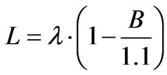
where:
L is the grating periodl is the RF radiation wavelengthB is the minimum allowable factor of RF radiation transmission through the window glass with the grating on it, to be selected within limits 0.3  0.95 (see dotted curve in Figure 1), c = 0.1
  0.7, d/L = 0.1
  0.5 and d £ L/100, while the angle between the stripe direction and the plane where the electrical field strength vector lies of the electromagnetic radiation passing through the grating is 90˚ ± 20˚; here d is the stripe width, and d is the conducting layer thickness.
For example, if a certain practical problem requires providing a glass radio transparency of B = 0.9, while the RF source operation wavelength is l = 10.7 mm (corresponding to frequency of 28 GHz), then we obtain the calculated grating period value:
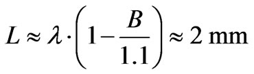 .
.
Taking into account the application limit d/L = 0.1  0.5, we can determine the width of stripes wherein the conducting layer is removed as around 0.2 mm. At higher carrier frequencies, such as 60 GHz, using the above approach we obtain a grating period of about 1 mm, and a transparent stripe width around 0.1 mm, which is also can be implemented.
2. Experiment
A laboratory experiment was made with three similar 130 × 130 mm square flat glass plates ~1.5 mm thick. Two of the plates were covered with an optically semitransparent aluminium layer (transparency about 30% in the visual band), while the third plate was left uncovered.
The measurement setup (see Figure 2) comprised a signal generator (the output signal frequency could be tuned or swept within a range 26 to 37 GHz), a small transmit horn antenna providing an output beam with linear polarization, an adjustable mount carrying one of the three glass plates, a receive horn antenna (similar to the transmit one), a detector head connected to the receive antenna by a waveguide, and an oscilloscope connected to the detector output. The signal generator operated in a low-frequency on-off keying mode.
The measured insertion loss introduced by the uncov-
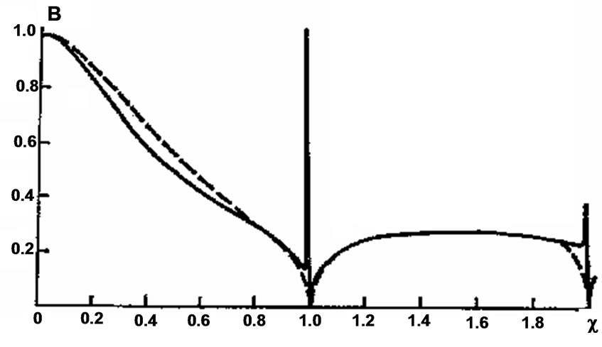
Figure 1. RF transmission factor B (B = 1 corresponds to 100% transmission) versus relative grating period c = L/l for a relative stripe width q = d/L = 0.2, and two values of relative coating thickness d (coating thickness to stripe width): d = 0 (dotted line), d = 0.025 (solid line).
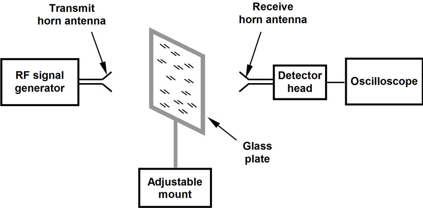
Figure 2. Block diagram of the experimental setup.
ered glass plate was 0.6  0.7 dB within the above frequency range, while the aluminium-coated plates introduced a loss of more than 25 dB. Thereafter, one of the two aluminium-coated plates has been processed by means of a laser scribing machine: 100 mm long and 0.15 mm wide stripes of the coating were removed, thus forming a grating with a period of 1 mm over an area 100 mm × 100 mm. The total processing time was less than 5 minutes.
The insertion loss introduced by the processed plate, as measured in the same setup with H-polarization (electromagnetic wave magnetic field vector parallel to the grating stripes direction), was 2.0  2.5 dB within the above frequency band and within a range of incidence angles (between the RF beam axis and the perpendicular to the glass plate surface) of ±45˚.
With the plate rotation around the axis perpendicular to its surface, the insertion loss increased, up to more than 25 dB for E-polarization (electromagnetic wave electric field vector parallel to the grating stripes direction).
In some cases double-glass windowpanes are used. Conductive coating is typically deposited on the inner surface of the double-glass pane, and it may be highly desirable to make the window transparent for microwaves without dissembling the double-glass pane. The problem may be solved by scanning the glass surface with a focused laser beam passing through the glass. To vaporize thin metal coating commercially available laser scribing equipment can be used, provided scanning area of the equipment is wide enough.
In our experiment, a double-glass window has been imitated by combining two glass plates with 0.5-inch spacing between them. One of the plates was uncoated, while the other was aluminium-coated, with the coating on the inner side of the plate. The “sandwich” was then processed in a manner similar to the above case, with the laser beam focused through the uncoated glass. The subsequent measurement results did not differ considerably from the ones related to single coated glass.
3. Conclusions
As demonstrated by the experiments, it is possible to make windows covered by conductive coatings transparent for electromagnetic radiation by removing a small share of the conductive coating, so that a grating is formed over an area of the window glass falling into the RF beam cross-section. Commercially available laser scribing equipment appeared to be an efficient tool for plotting non-conductive structures on conductive coating.
If the scanned area of the laser scribing tool is limited, the necessary radio transmission “window” required for beams several tens of centimeter in diameter may be combined of several smaller areas, where the stripes of each area may be displaced relative to the stripes in adjacent areas. Such a combined “mosaic” grating will not cause considerable phase or amplitude distortion in the output electromagnetic beam, as the phase of electromagnetic wave passing through the grating does not depend on transverse position of the grating stripes.
It is also worth noting that if, for any reason, the RFtransparent coating should maintain transparency for any RF beam polarization, crossed gratings may be used (i.e., after removal of the coating within stripes along a certain direction, the same procedure should be repeated with a stripe direction perpendicular to the former one, over the same area; also more complicated structures looking like honeycomb cells may be efficiently used, [1]). The nonconducting paths will then form isolated areas of conductive coating. If the conductive areas are smaller that the RF beam wavelength, excitation of electric current is blocked in the coating thus making a resulting surface sufficiently transparent for any polarization of the RF beam.
REFERENCES
- V. Sidorovich, “Architectural Window Glass,” Russian Federation Patent for Useful Model #34612, Filed 9 January 2003.
- V. P. Shestopalov, A. A, Kirilenko, S. A. Masalov and Y. K. Syrenko, “Resonant Wave Scattering,” Vol. 1, Diffraction Gratings, Naukova Dyumka, Kiev, 1986.