Engineering
Vol. 3 No. 9 (2011) , Article ID: 7337 , 6 pages DOI:10.4236/eng.2011.39118
Experimental Analysis of Heat Transfer Behavior inside Heat Pipe Integrated with Cooling Plates
1Department of Mechanical Engineering, National Taipei University of Technology, Chinese Taipei
2Institute of Mechanical and Electrical Engineering, National Taipei University of Technology, Chinese Taipei
E-mail: *chchting@ntut.edu.tw, s3300357@ntut.edu.tw
Received July 1, 2011; revised August 12, 2011; accepted August 22, 2011
Keywords: Heat Transfer Behavior, Heat Pipe, Color Schlieren, Infrared Thermography, Heat Pipe Cooler
ABSTRACT
This work used experimental methods to study heat transfer behavior inside a heat pipe and found that heat transfer behavior inside the heat pipe was changed due to its integration with cooling plates. This change caused the heat pipe to have copper-like heat transfer behavior. Experimental performances first built a CPU simulator with maximum heat power 300 W in accordance with the ASTM standard as heat source and measured temperature distribution by using infrared thermography and thermocouple thermometer. Observation of heat transfer behavior inside heat pipe influenced by its integration with cooling plates used color schlieren technique. A commercial CPU heat pipe cooler was also used as reference object in this work. Integration of the heat pipe with cooling plates causes the heat pipe to have the copper-like heat transfer behavior. The results indicate that rebuilding the bare heat pipe’s heat transfer behavior is the best solution for improving cooling efficiency of the heat pipe cooler.
1. Introduction
The general principle of heat pipe employs evaporative cooling on the heat source with the working fluid and its capillary action transports the condensed fluid back to the evaporating section. It was first noted by Grover at Los Alamos National Laboratory in 1963 and subsequently published in the Journal of Applied Physics in 1964 [1]. A heat pipe is a passive cooling device with extremely high thermal conductivity ca. 5000 ~ 30,000 [W/mK], which is initiated by a special heat transfer mechanism and can transport relatively large amount of heat in a tiny temperature difference between the hot and the cold interfaces. The heat pipe is hence often named as the thermal superconductor. Stenger in 1966 [2] first developed the technique of capillary pumped loop (CPL) in heat pipe and Maydanik et al. in 1985 originally developed the loop heat pipe (LHP) for the terrestrial solar energy market using the technique of anti-gravitation heat pipe [3].
The heat transfer property of heat pipe is theoretically different from that of copper pipe. Heat pipe is spatially discrete, whereas the copper pipe is continuous. Heat pipe for cooling has been widely used in the market due to its extremely large value of thermal conductivity and normally combined with the cooling finny pieces, named as the heat pipe cooler. The heat pipe cooler should have theoretically excellent cooling efficiency, but the fact is that it cannot reach the predicted value. This is the main question for applications of the heat pipe cooler. Most of the studies on the heat pipe cooler ignored the considerations on the heat transfer behavior change of heat pipe due to the integration with the cooling plates and discussed only its integrating structure. Bejan and Scibba in 1992 [4] indicated that the optimal condition of the cooling plates is dependent on the three parameters,  ,
,  ,
,  ,for the heat pipe cooler, where L is length of the cooling plates,
  is viscosity of the cooling fluid,
 ![]() is thermal diffusivity of the cooling fluid, and
is thermal diffusivity of the cooling fluid, and  is pressure difference of the in and out cooling fluid. Yeh and Chang in 1995 [5] show an optimal design for heat pipe cooler. There are a lot of studies about the improvement of the cooling efficiency for heat pipe cooler, but their discussions were almost focused on the integrating structural design [6-8].
Studies on the heat transfer behavior inside the heat pipe are relatively few. A standard application of heat pipe is in connection with cooling plates, but the integration has changed the original heat transfer property of the heat pipe. The heat transfer behavior of heat pipe is similar to copper pipe due to the integration with cooling plates, which certainly reduces its cooling efficiency.
This work discusses the inner heat transfer property change of heat pipe integrated with cooling plates using experimental methods. It found that the change of heat transfer behavior inside heat pipe integrated with cooling plates is the main reason for the lack cooling efficiency. The cooling plates far from the heat source cannot reach sufficient cooling efficiency. This work found also that a new structure of heat pipe for integration with cooling plates should be designed to keep the original heat transfer behavior of bare heat pipe after integration with cooling plates [9].
2. Basic Theory
A heat pipe is theoretically divided into three parts, the evaporator, the adiabatic section, and the condenser. Figure 1 shows schematics of a bare heat pipe. In process, the working fluid absorbs heat from heat source and evaporates in the evaporator. The hot vapor directly runs through the adiabatic section and condenses in the condenser. The condensed working fluid in the condenser runs back by way of the capillary structure on the inner wall in the adiabatic section and reaches the evaporator again.
Figure 2 shows schematics of a common heat pipe cooler, where the convective heat transfer to the cooling fin continuously decreases. A common heat pipe cooler is integrated with cooling fin in the adiabatic section. Due to integration of the cooling fin with heat pipe in the adiabatic section, the heat of the vapor is forcedly taken away by the cooling fin in the adiabatic section and therefore condenses earlier. In other words, the vapor cannot reach the condenser section and the adiabatic section disappears. This result will shorten the effective cooling length of the heat pipe. The original heat transfer property of the heat pipe integrated with cooling fin in the adiabatic section is unfortunately destroyed by integration of the cooling fin with the heat pipe and is changed to be similar to copper pipe, where the bare heat pipe is discrete and the copper pipe is continuous.
To increase cooling efficiency of a heat pipe cooler, temperature distribution on the heat pipe should be more uniform. That is, the original heat transfer property of the heat pipe in a heat pipe cooler should be recovered. In other words, the adiabatic section must be kept. A future
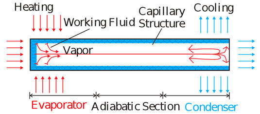
Figure 1. Schematics of a bare heat pipe [10].
application of this work is the so-called dual-pipe heat pipe cooler [10]. Figure 3 shows schematics of a dual-pipe heat pipe cooler, where the convective heat transfer to the cooling fin is more uniform. A dual-pipe heat pipe builds the inner coaxial pipe in the adiabatic section of a common heat pipe. The built inner coaxial pipe can avoid heat of the vapor to be taken away in the adiabatic section. This special design lets the vapor be able to run through the adiabatic section and successfully recover the original heat transfer property of the heat pipe for a heat pipe cooler.
3. Experimental Details
A CPU simulator was built as the heat source in this work and the experiments were done by using the color schlieren, the infrared thermography, and the thermocouple thermometer for temperature determination. The built CPU simulator in accordance with the ASTM D5470 standard consists of a T form copper block, some glass wool, fireproof board, two 150 W cartridge heaters, and a 300 W power supply. Figure 4 shows the schematic description of the built CPU simulator, where the temperature on the
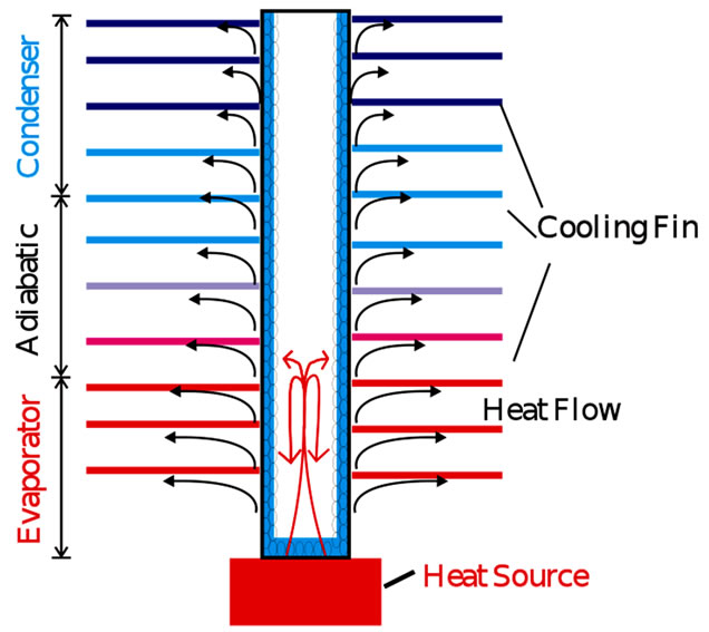
Figure 2. Schematics of a heat pipe cooler [10].
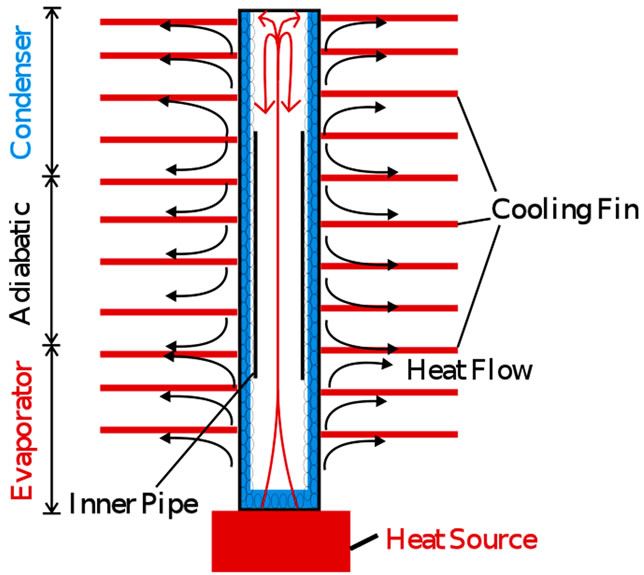
Figure 3. Schematics of a dual-pipe heat pipe cooler [10].
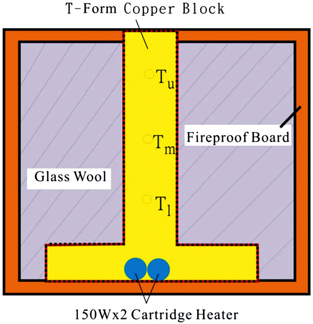
Figure 4. Schema of the CPU simulator’s side cross section.
three points Tu,, Tm, and Tl are used to determine the simulated CPU power.
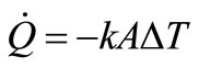
According to the Fourier’s equation:
 (1)
(1)
where  is the rate of heat flow over the area A and T is temperature. The negative sign indicates that the temperature gradient is in the opposite direction to the heat flow and k is the thermal conductivity of the material. Application of the one-dimensional Fourier’s equation for determination of the CPU simulator output heat flow rate
  receives
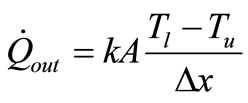 (2)
(2)
where  is the positional difference of points Tl and Tu, A is 31 × 31 mm2. Figure 5 shows the calibration curve of the input and output powers corresponding to the power supply and the CPU simulator, respectively. The function of the fitted curve is y = 0.93x – 0.31 with
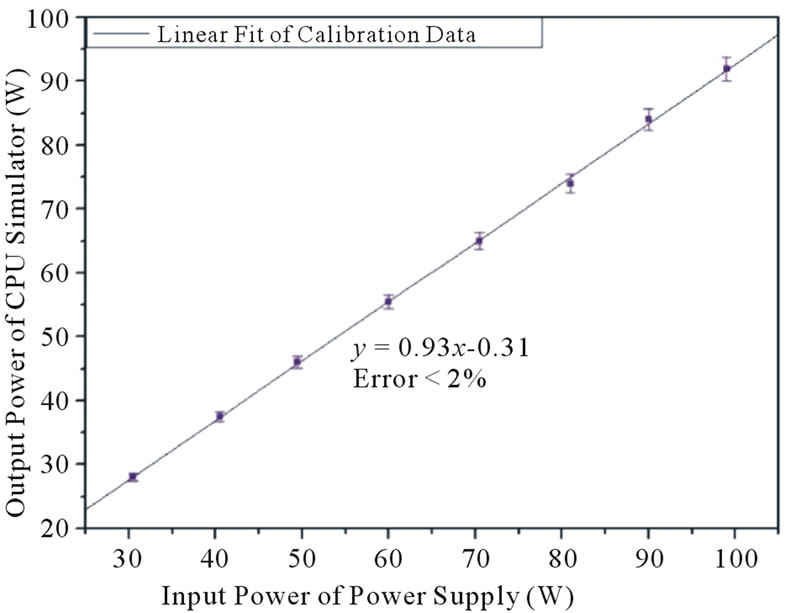
Figure 5. Calibration curve of the CPU simulator [9].
the fitting error smaller than 2%.
Figure 6 shows photo of the heat pipe built on the CPU simulator. The experimental setup used the IRISYS infrared thermal camera, which has resolution of 16 × 16 pixels and capturing speed of 8 fps, to record the time dependent change of the temperature distribution on the heated heat pipe.
The capturing screen of the infrared thermal camera shows the 16 × 16 pixels corresponding to 16 × 16 temperature sensors. Figure 7 represents the corresponding positions with the heated heat pipe, which will be applied to the data evaluation.
Observation of the heat transfer behavior inside the heat pipe influenced by the integration with cooling plates used the color schlieren technique. This experimental setup was built in water tank due to the water has larger thermal conductivity than air. The water was set as a good cooling medium for the heat pipe. Figure 8 shows the schematic setup of the heat pipe integrated with cooling plates. The sequent
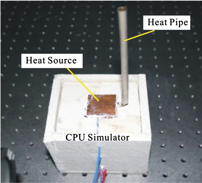
Figure 6. Photo of the heat pipe built on the CPU simulator.
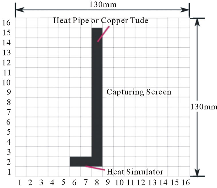
Figure 7. Capturing screen of the infrared thermal camera corresponding to the position of the heated heat pipe.
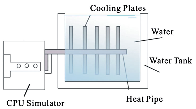
Figure 8. Schematic setup of the heat pipe in connection with the cooling plates.
heating by the heat source convects heat into the water and yields the simultaneous heat flux which was visualized by the color schlieren technique.
A commercial heat pipe cooler with U-form heat pipe was used as the reference object. Its heat pipe has total length 265 mm and diameter  6 mm in connection with 25 pieces cooling plates which have each thickness 0.46 mm and area 87 × 20 mm2. There are 5 different points on the heat pipe for determination of the temperature distribution. Figure 9 shows the sketch and Figure 10 is photo of the setup.
In process, the copper pipe and the conventional heat pipe are individually connected with the CPU simulator for developing temperature measurements without outside cooling. These measurements can determine heat transfer properties of the copper pipe and the heat pipe. In principle, heat transfer property of the copper pipe is continuous and the heat pipe is discrete. After that, a commercial heat pipe cooler is connected with the CPU simulator for determination of the surface temperature
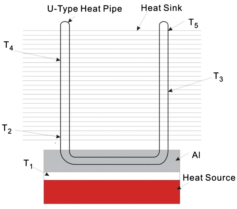
Figure 9. Schema of the measured temperature points in the heat pipe cooler.
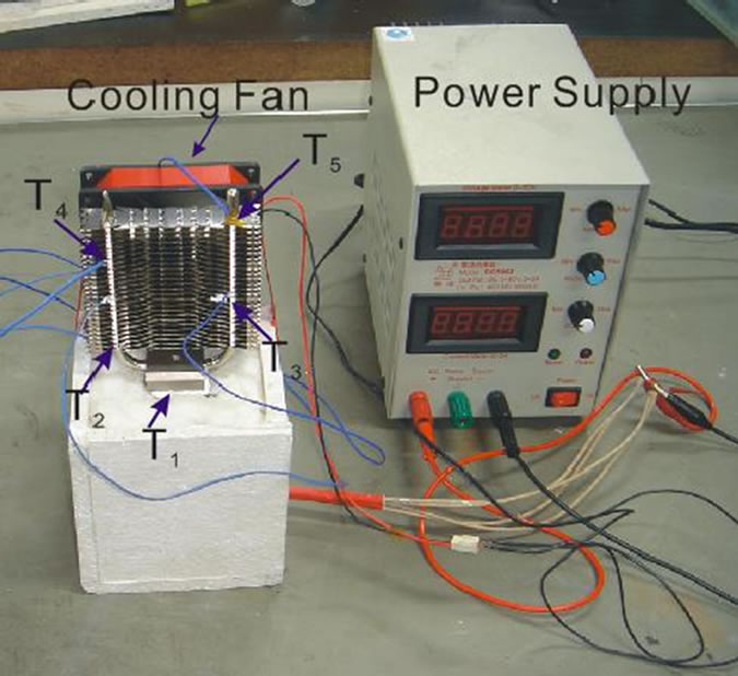
Figure 10. Photo of the measured heat pipe cooler.
distribution on the heat pipe. These measurements will show heat transfer property of the heat pipe influenced by the outside cooling fin. In comparison with the commercial heat pipe cooler uses the heat pipe to be immersed into water for visualization of the developing heat flux. The water is applied as the outside cooling medium in this work. The time-varying schlieren photos will show heat transfer property of the heat pipe.
4. Results and Discussion
Experimental data for discussing discrete heat transfer behavior of the heat pipe in comparison with the copper pipe’s continuous property are shown in Figures 11 and 12. Figure 11 shows the temperature distribution on the copper pipe heated under adiabatic condition by the 300W CPU simulator in 117sec [9]. The arabic positional numerals shown in Figures 11 and 12 are the measured positions corresponding to the distance from the heat source. The temperature change on the copper pipe is continuous. Figure 11 shows that the temperature distribution on the copper pipe gradually reduces away from the heat source. This result agrees to the traditional thermal conduction theorem and also satisfies the Fourier’s thermal conduction equation. In comparison with the result of the heat pipe in Figure 11, it is found that the change of surface temperature distribution on the heat pipe nearby the heat source is weaker than the endpoint which is under the same experimental condition. Figure 12 shows that the discrete temperature distribution on the heat pipe in middle field has the lowest temperature.
The result shown in Figure 12 agrees to the theoretically described heat transfer behavior of the heat pipe. The evaporated working fluid saves latent heat from the heat source and expands directly to the remote condensed section. The heat transfer via the vapor expansion
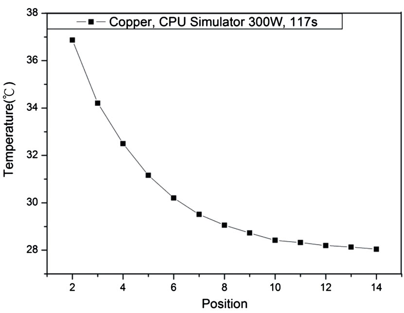
Figure 11. Relationship of temperature distribution on the bare copper pipe.
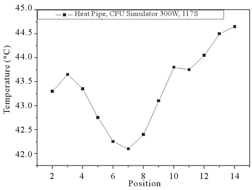
Figure 12. Relationship of temperature distribution on the bare heat pipe.
technism inside the heat pipe is relatively quick than via the thermal conduction through the outer copper shell. This special heat transfer technism let it have extremely large thermal conductivity. The temperature on positions 2 and 3 in Figure 12 appears unstability because vaporization was happening there.
Figure 13 is the temperature distribution on the heat pipe which is built in the commercial heat pipe cooler. The heat pipe cooler has been heated by 30.8 W thermal power for 40 mins. The heat transfer behavior shown in Figure 13 is similar to the copper pipe in Figure 11. That means, the heat transfer behavior inside the heat pipe was altered by the addition of the cooling plates. In other words, the cooling plates changed the heat transfer behavior of the heat pipe.
The special heat transfer technism of the heat pipe is further described by the direct observation of heat flux using the color schlieren technique. Water has larger
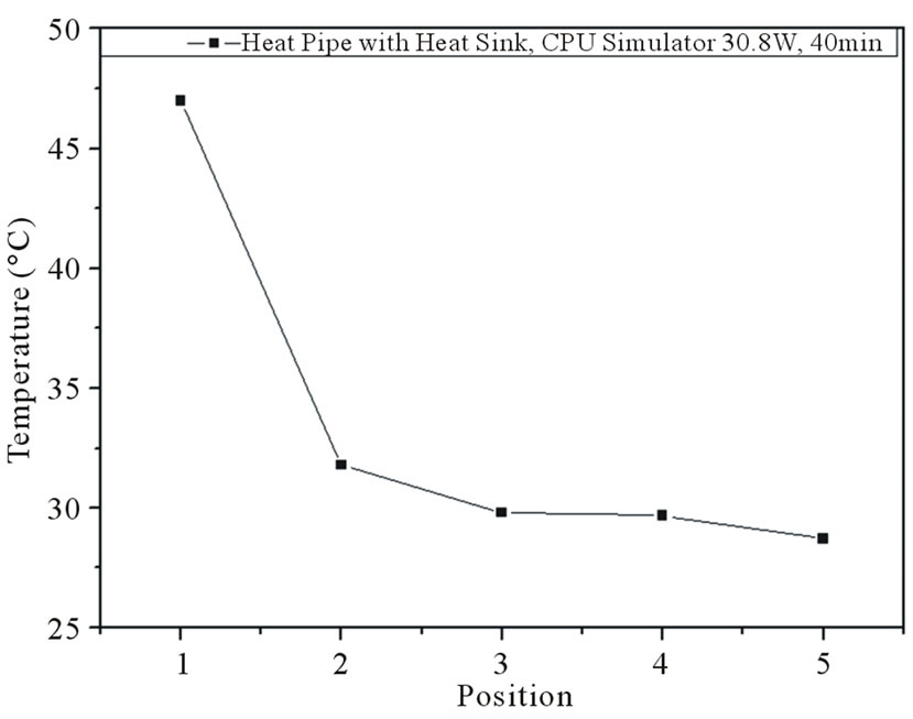
Figure 13. Relationship of temperature distribution on a commercial heat pipe cooler.
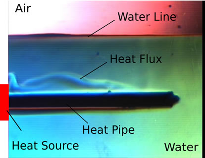
thermal conduction coefficient Kwater ≈ 2.526 [W/mK] than air Kair ≈ 0.23[W/mK] [11]. The water around the heat pipe is like the cooling apparatus while the heat pipe is immersed into the water tank for heat flux visualization [12]. The heat pipe transferred the heat into the water and changed the density distribution of the water, which was visualized by the color schlieren technique. Figures 11 exhibit four time sequent color schlieren images with the heated bare heat pipe. Figures 11 show that the horizontal dark bar in the middle is the heat pipe and the separation line upper the heat pipe is the water level. Figure 14(a) is at the begin and shows no heat flux around the heat pipe. Figures 14(b) and (c) show clearly the development of the heat flux away from the heat source. Figures 14(a) and (b) exhibit indirectly that the heat transfer inside the heat pipe happens from the heat source and runs away continuously. Around the full heat pipe shows clearly the continuous heat flux from the left image to the right image. That means, the theoretically adiabatic middle section appears clearly thermal convection with the water. This significant result indicates further that the evaporated heat cannot be effectively brought to the remote condensed section, if the surroundings of the heat pipe has good thermal conductivity.
Heat pipe cooler uses normally aluminum plates as the cooling apparatus to take away heat from the heat pipe. The aluminum cooling plates have large thermal conduction coefficient KAl ≈ 230[W/mK] [11]. In this work, the surrounding water plays the role of the integrated cooling plates in heat pipe cooler. Figure 11 indirectly indicates that the integration of cooling plates changes really the original heat transfer behavior of the bare heat pipe. This result completely agrees to the experimental data shown in Figure 10. The changed heat transfer behavior of heat pipe
 (a)
(a)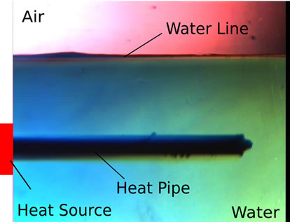 (b)
(b)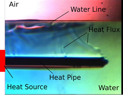 (c)
(c)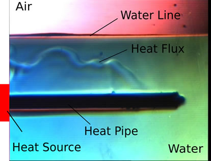 (d)
(d)
Figure 14. The heated time sequent color schlieren image with the heat pipe. (a) The heated time is 0sec. (b) The heated time is 15sec. (c) The heated time is 18sec. (d) The heated time is 22sec.
integrated with cooling plates reduces also its cooling efficiency. This paper indicates the fact that rebuilding the original heat transfer behavior of the bare heat pipe is the proper way for improving the cooling efficiency of the heat pipe cooler.
5. Conclusions
Temperature measurements using infrared thermography and thermocouple thermometer on the heat pipe as well as heat flux visualization around the heat pipe using color schlieren technique were successfully carried out. The results show that the heat transfer behavior of copper pipe is continuous, whereas heat pipe is discrete. The temperature distribution on heat pipe built-in heat pipe cooler shows good similarity to copper pipe. Time sequent color schlieren images show the same result as the temperature measurements. This work illustrates that the heat transfer behavior inside the heat pipe is changed to be similar to the copper pipe due to the integration with the cooling plates. Rebuilding the bare heat pipe’s heat transfer behavior is the best solution for improving the cooling efficiency of the heat pipe cooler due to the original heat transfer behavior of the heat pipe has the best uniform temperature.
6. Acknowledgements
The authors would like to acknowledge the financial support from the National Science Foundation of Taiwan under Grant No. NSC97-2221-E-027-031.
7. REFERENCES
- G. M. Grover, T. P. Cotter and G. F. Erickson, “Structures of Very High Thermal Conductance,” Journal of Applied Physics, Vol. 35, No. 6, 1964, pp. 1990-1991. doi:10.1063/1.1713792
- F. J. Stenger, “Capillary Pumped Loop-CPL,” NASA TM X-1310, 1996.
- S. V. Vershini and Y. F. Maydanik, “Hysteresis Phenomena in Loop Heat Pipes,” Applied Thermal Engineering, Vol. 27, No. 5-6, 2007, pp. 962-968. doi:10.1016/j.applthermaleng.2006.08.016
- A. Bejan and E. Sciubba, “The Optimal Spacing of Parallel Plates Cooled by Forced Convection,” International Journal of Heat and Mass Transfer, Vol. 35, No. 12, 1992, pp. 3259-3264. doi:10.1016/0017-9310(92)90213-C
- R. H. Yeh and M. Chang, “Optimum Longitudinal Convective Fin Arrays,” International Communications in Heat and Mass Transfer, Vol. 22, No. 3, 1995, pp. 445-460. doi:10.1016/0735-1933(95)00029-X
- P. L. Dhar and C. P. Arora, “Optimum Design of Finned Surface,” Journal of the Franklin Institute, Vol. 301, No. 4, 1976, pp. 379-392. doi:10.1016/0016-0032(76)90088-0
- B. Kundu and P. K. Das, “Performance and Optimum Design Analysis of Convective Fin Arrays Attached to Flat and Curved Primary Surfaces,” International Journal of Refrigeration, Vol. 32, No. 3, 2009, pp. 430-443. doi:10.1016/j.ijrefrig.2008.08.012
- H. S. Kou, J. J. Lee and C. Y. Lai, “Thermal Analysis and Optimum Fin Length of a Heat Sink,” Heat Transfer Engineering, Vol. 24, No. 2, 2003, pp. 18-29. doi:10.1080/01457630304083
- C. C. Ting, J. N. Lee and C. C. Chen, “Heat Transfer Characterizations of Heat Pipe in Comparison with Copper Pipe,” Journal of Heat Transfer, Vol. 131, No. 3, 2009, pp. 1-6. doi:10.1115/1.3056571
- C. C. Ting and C. C. Chen, “Developing the Coaxial Dual-Pipe Heat Pipe for Applications on Heat Pipe Cooler,” Journal of Heat Transfer, Vol. 133, No. 9, 2011. doi:10.1115/1.4003904
- J. M. Coulson and J. F. Richardson, “Fluid Flow, Heat Transfer and Mass Transfer,” Butterworth-Heinemann Ltd., Oxford, 1999.
- H. Kleine, “Application and Limitation of a Schlieren System,” RWTH-Aachen Germany, Report, No. WLS 12823, 1994.