Paper Menu >>
Journal Menu >>
 Engineering, 2010, 2, 60-64 doi:10.4236/eng.2010.21008 lished Online January 2010 (http://www.SciRP.org/journal/eng/). Copyright © 2010 SciRes. ENGINEERING Pub Research on Early Fault Self-Recovery Monitoring of Aero-Engine Rotor System Zhongsheng WANG, Shiwe MA School of Aeronautics Northwestern Polytechnical University Xi’an, China Email: sazs_wang@nwpu.edu.cn Received August 19, 2009; revised September 14, 2009; accepted September 20, 2009 Abstract In order to increase robustness of the AERS (Aero-engine Rotor System) and to solve the problem of lacking fault samples in fault diagnosis and the difficulty in identifying early weak fault, we proposed a new method that it not only can identify the early fault of AERS but also it can do self-recovery monitoring of fault. Our method is based on the analysis of the early fault features on AERS, and it combined the SVM (Support Vector Machine) with the stochastic resonance theory and the wavelet packet decomposition and fault self-recovery. First, we zoom the early fault feature signals by using the stochastic resonance theory. Second, we extract the feature vectors of early fault using the multi-resolution analysis of the wavelet packet. Third, we input the feature vectors to a fault classifier, which can be used to identify the early fault of AERS and carry out self-recovery monitoring of fault. In this paper, features of early fault on AERS, the zoom of early fault characteristics, the extraction method of early fault characteristics, the construction of multi-fault clas- sifier and way of fault self-recovery monitoring are studied. Results show that our method can effectively identify the early fault of AERS, especially for identifying of fault with small samples, and it can carry on self-recovery monitoring of fault. Keywords: AERS, Early Fault, Support Vector Machine, Classification Identification of Fault, Self-Recovery Monitoring of Fault 1. Introduction With the development of the modern aviation industry, the safety of aircraft and reliability are more and more attracted. The engine is heart of aircraft and AERS is central part of engine. If AERS has fault in flight, the aircraft would be severely threatened in safety. Because the structure of AERS is complex, load is bigger and the change of operation conditions is frequency, it will be the more difficult in the fault identification. Especially in the early failures occurred, if we can catch timely the fault information, and can effectively identify it and carry on self-recovery monitoring of fault, it will have important significance to eradicate or eliminate the potential fault caused of an accident. Fault identification on AERS is widely studied and many results are obtained [1−3]. At present now, effective identification of early fault has more difficulty. In particular, obtaining of the early fault information is more difficulty, and effectiveness of fault identification is not satisfactory. Because operation of AERS is in strong noise density, the early fault informa- tion is very weak and signals are easily flooded in noises, satisfactory results are very difficult by general methods. Our method can not only fast identify the early fault of the AERS but also carry on self-recovery monitory of fault. 2. Features of Early Fault on AERS In the flight, the wear, deformation, corrosion and frac- ture of structure components and effects of work stress, external environment and human factors will lead to faults of AERS. The early fault of AERS often shows a form in micro-cracks, micro-creeping, micro-corrosion and micro-wear. These faults, with the exception of little sudden faults, the majority have a development process from nothing to fault, minor to general, evolution to fast. In this process, the structure of system, properties and internal energy will change. We can monitor the early faults through catching these fault information in time, *Project (50675178, 60472116) Supported by National Natural Science Foundation of China 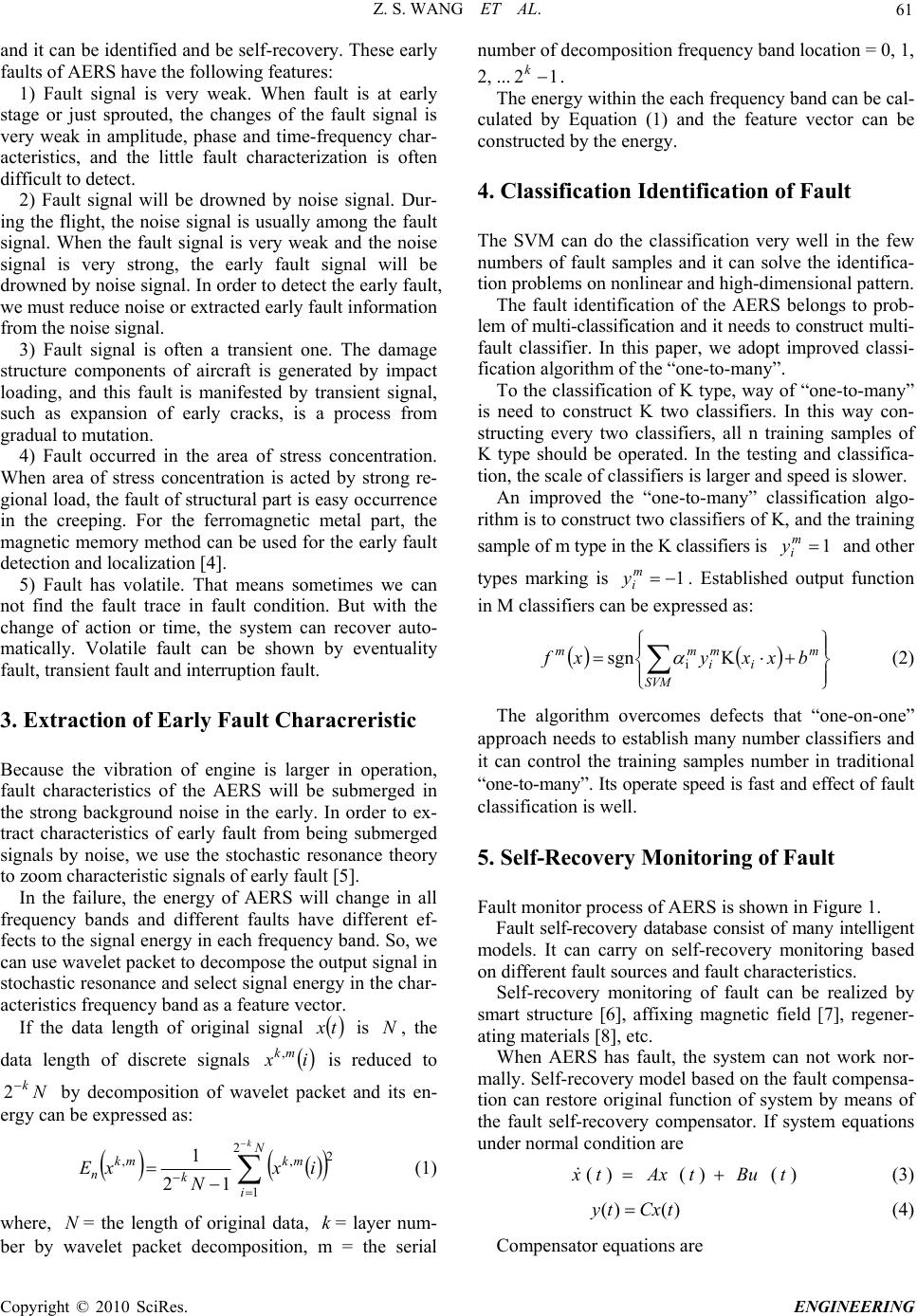 Z. S. WANG ET AL. 61 and it can be identified and be self-recovery. These early faults of AERS have the following features: 1) Fault signal is very weak. When fault is at early stage or just sprouted, the changes of the fault signal is very weak in amplitude, phase and time-frequency char- acteristics, and the little fault characterization is often difficult to detect. 2) Fault signal will be drowned by noise signal. Dur- ing the flight, the noise signal is usually among the fault signal. When the fault signal is very weak and the noise signal is very strong, the early fault signal will be drowned by noise signal. In order to detect the early fault, we must reduce noise or extracted early fault information from the noise signal. 3) Fault signal is often a transient one. The damage structure components of aircraft is generated by impact loading, and this fault is manifested by transient signal, such as expansion of early cracks, is a process from gradual to mutation. 4) Fault occurred in the area of stress concentration. When area of stress concentration is acted by strong re- gional load, the fault of structural part is easy occurrence in the creeping. For the ferromagnetic metal part, the magnetic memory method can be used for the early fault detection and localization [4]. 5) Fault has volatile. That means sometimes we can not find the fault trace in fault condition. But with the change of action or time, the system can recover auto- matically. Volatile fault can be shown by eventuality fault, transient fault and interruption fault. 3. Extraction of Early Fault Characreristic Because the vibration of engine is larger in operation, fault characteristics of the AERS will be submerged in the strong background noise in the early. In order to ex- tract characteristics of early fault from being submerged signals by noise, we use the stochastic resonance theory to zoom characteristic signals of early fault [5]. In the failure, the energy of AERS will change in all frequency bands and different faults have different ef- fects to the signal energy in each frequency band. So, we can use wavelet packet to decompose the output signal in stochastic resonance and select signal energy in the char- acteristics frequency band as a feature vector. If the data length of original signal is , the data length of discrete signals is reduced to by decomposition of wavelet packet and its en- ergy can be expressed as: tx N ix mk, N k 2 N i mk k mk n k ix N xE 2 1 2 ,, 12 1 (1) where, = the length of original data, = layer num- ber by wavelet packet decomposition, m = the serial number of decomposition frequency band location = 0, 1, 2, ... N k 12 k m f . The energy within the each frequency band can be cal- culated by Equation (1) and the feature vector can be constructed by the energy. 4. Classification Identification of Fault The SVM can do the classification very well in the few numbers of fault samples and it can solve the identifica- tion problems on nonlinear and high-dimensional pattern. The fault identification of the AERS belongs to prob- lem of multi-classification and it needs to construct multi- fault classifier. In this paper, we adopt improved classi- fication algorithm of the “one-to-many”. To the classification of K type, way of “one-to-many” is need to construct K two classifiers. In this way con- structing every two classifiers, all n training samples of K type should be operated. In the testing and classifica- tion, the scale of classifiers is larger and speed is slower. An improved the “one-to-many” classification algo- rithm is to construct two classifiers of K, and the training sample of m type in the K classifiers is and other types marking is . Established output function in M classifiers can be expressed as: 1 m i y 1 m i y m SVM i m i mbxxyx Ksgn i (2) The algorithm overcomes defects that “one-on-one” approach needs to establish many number classifiers and it can control the training samples number in traditional “one-to-many”. Its operate speed is fast and effect of fault classification is well. 5. Self-Recovery Monitoring of Fault Fault monitor process of AERS is shown in Figure 1. Fault self-recovery database consist of many intelligent models. It can carry on self-recovery monitoring based on different fault sources and fault characteristics. Self-recovery monitoring of fault can be realized by smart structure [6], affixing magnetic field [7], regener- ating materials [8], etc. When AERS has fault, the system can not work nor- mally. Self-recovery model based on the fault compensa- tion can restore original function of system by means of the fault self-recovery compensator. If system equations under normal condition are )()()( tButAxtx (3) )()( tCxty (4) Compensator equations are C opyright © 2010 SciRes. ENGINEERING 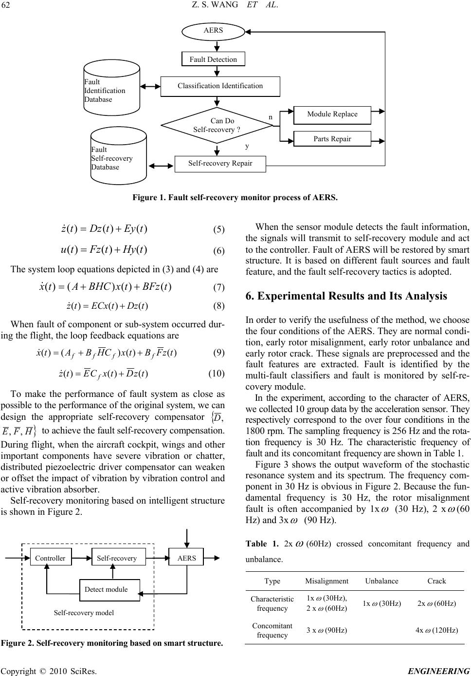 Z. S. WANG ET AL. Copyright © 2010 SciRes. ENGINEERING 62 AERS Fault Detection Classification Identification Fault Identification Database Can Do Self-recovery ? Self-recovery Repair Fault Self-recovery Database Module Replace Parts Repair y n Figure 1. Fault self-recovery monitor process of AERS. When the sensor module detects the fault information, the signals will transmit to self-recovery module and act to the controller. Fault of AERS will be restored by smart structure. It is based on different fault sources and fault feature, and the fault self-recovery tactics is adopted. )()()(tEytDztz (5) )()()( tHytFztu (6) The system loop equations depicted in (3) and (4) are )()()()( tBFztxBHCAtx (7) 6. Experimental Results and Its Analysis )()()( tDztECxtz (8) In order to verify the usefulness of the method, we choose the four conditions of the AERS. They are normal condi- tion, early rotor misalignment, early rotor unbalance and early rotor crack. These signals are preprocessed and the fault features are extracted. Fault is identified by the multi-fault classifiers and fault is monitored by self-re- covery module. When fault of component or sub-system occurred dur- ing the flight, the loop feedback equations are )()()()( tzFBtxCHBAtxffff (9) )()()( tzDtxCEtzf (10) To make the performance of fault system as close as possible to the performance of the original system, we can design the appropriate self-recovery compensator ,D HFE ,, to achieve the fault self-recovery compensation. During flight, when the aircraft cockpit, wings and other important components have severe vibration or chatter, distributed piezoelectric driver compensator can weaken or offset the impact of vibration by vibration control and active vibration absorber. In the experiment, according to the character of AERS, we collected 10 group data by the acceleration sensor. They respectively correspond to the over four conditions in the 1800 rpm. The sampling frequency is 256 Hz and the rota- tion frequency is 30 Hz. The characteristic frequency of fault and its concomitant frequency are shown in Table 1. Figure 3 shows the output waveform of the stochastic resonance system and its spectrum. The frequency com- ponent in 30 Hz is obvious in Figure 2. Because the fun- damental frequency is 30 Hz, the rotor misalignment fault is often accompanied by 1x (30 Hz), 2 x (60 Hz) and 3x (90 Hz). Self-recovery monitoring based on intelligent structure is shown in Figure 2. Controller Self-recovery AERS Self-recovery model Detect module Table 1. 2x (60Hz) crossed concomitant frequency and unbalance. Type MisalignmentUnbalance Crack Characteristic frequency 1x (30Hz), 2 x (60Hz) 1x (30Hz) 2x (60Hz) Concomitant frequency 3 x (90Hz) 4x (120Hz) Figure 2. Self-recovery monitoring based on smart structure. 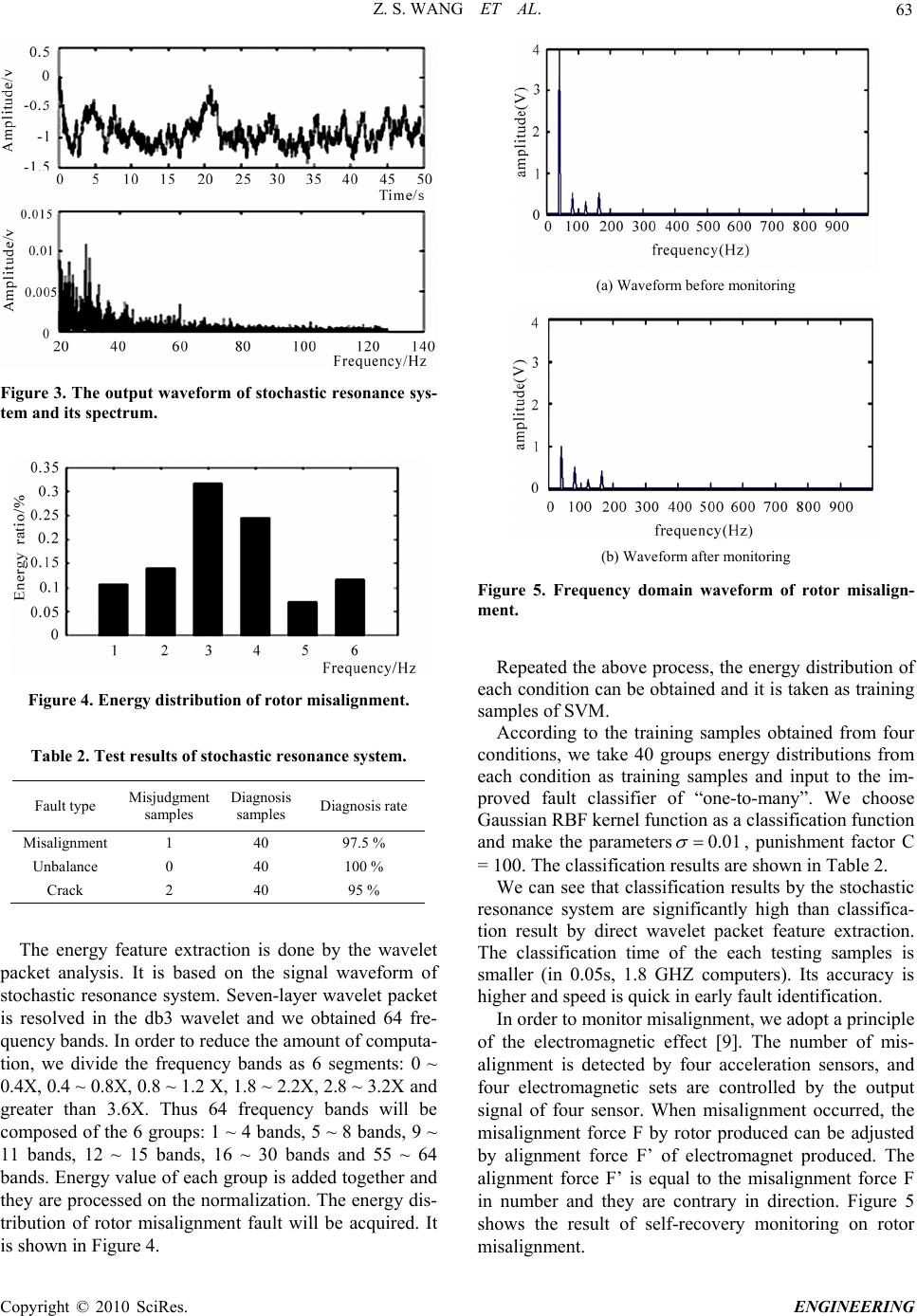 Z. S. WANG ET AL. 63 Figure 3. The output waveform of stochastic resonance sys- tem and its spectrum. Figure 4. Energy distribution of rotor misalignment. Table 2. Test results of stochastic resonance system. Fault type Misjudgment samples Diagnosis samples Diagnosis rate Misalignment 1 40 97.5 % Unbalance 0 40 100 % Crack 2 40 95 % The energy feature extraction is done by the wavelet packet analysis. It is based on the signal waveform of stochastic resonance system. Seven-layer wavelet packet is resolved in the db3 wavelet and we obtained 64 fre- quency bands. In order to reduce the amount of computa- tion, we divide the frequency bands as 6 segments: 0 ~ 0.4X, 0.4 ~ 0.8X, 0.8 ~ 1.2 X, 1.8 ~ 2.2X, 2.8 ~ 3.2X and greater than 3.6X. Thus 64 frequency bands will be composed of the 6 groups: 1 ~ 4 bands, 5 ~ 8 bands, 9 ~ 11 bands, 12 ~ 15 bands, 16 ~ 30 bands and 55 ~ 64 bands. Energy value of each group is added together and they are processed on the normalization. The energy dis- tribution of rotor misalignment fault will be acquired. It is shown in Figure 4. (a) Waveform before monitoring (b) Waveform after monitoring Figure 5. Frequency domain waveform of rotor misalign- ment. Repeated the above process, the energy distribution of each condition can be obtained and it is taken as training samples of SVM. According to the training samples obtained from four conditions, we take 40 groups energy distributions from each condition as training samples and input to the im- proved fault classifier of “one-to-many”. We choose Gaussian RBF kernel function as a classification function and make the parameters01.0 , punishment factor C = 100. The classification results are shown in Table 2. We can see that classification results by the stochastic resonance system are significantly high than classifica- tion result by direct wavelet packet feature extraction. The classification time of the each testing samples is smaller (in 0.05s, 1.8 GHZ computers). Its accuracy is higher and speed is quick in early fault identification. In order to monitor misalignment, we adopt a principle of the electromagnetic effect [9]. The number of mis- alignment is detected by four acceleration sensors, and four electromagnetic sets are controlled by the output signal of four sensor. When misalignment occurred, the misalignment force F by rotor produced can be adjusted by alignment force F’ of electromagnet produced. The alignment force F’ is equal to the misalignment force F in number and they are contrary in direction. Figure 5 shows the result of self-recovery monitoring on rotor misalignment. C opyright © 2010 SciRes. ENGINEERING  Z. S. WANG ET AL. Copyright © 2010 SciRes. ENGINEERING 64 We can find out that vibration of rotor is obviously reduced in Figure 5(a) and Figure 5(b). Because of the misalignment fault of rotor is counteracted by the elec- tromagnet force, the rotor misalignment is inhibited and the normal operation condition is restored well. 7. Conclusions 1) Our method can effectively extract the early fault fea- ture of the AERS by combination the stochastic reso- nance with the wavelet packet resolving. Energy eigen- vectors of constructed by this methods can accurately reflect the condition changes of AERS. 2) Multi-fault classifier based on the SVM has charac- teristics that its algorithm is simpler, the classification effect is well and identification efficiency is higher. It particularly suits to the classification identification of small sample and self-recovery monitoring of early fault on AERS. 3) The fault diagnosis is aimed at finding failure in time and to ensure safe operation of plant. The method of fault self-recovery monitoring provides an effective way. 8. References [1] D. Simon, “A comparison of filtering approaches for aircraft engine health estimation,” Aerospace Science and Technology, Vol. 12, No. 4, pp. 276–284, 2008. [2] S. Borguet and O. Léonard, “Coupling principal compo- nent analysis and Kalman filtering algorithms for on-line aircraft engine diagnostics,” Control Engineering Practice, Vol. 17, No. 4, pp. 494–502, 2009. [3] T. Ramesh Babu and A. S. Sekhar, “Detection of two cracks in a rotor-bearing system using amplitude devia- tion curve,” Journal of Sound and Vibration, Vol. 314, No. 3–5, pp. 457–464, 2008. [4] A. Dubov and S. Kolokoinikov, “Review of welding pro- blems and allied processes and their solution using the metal magnetic memory effect,” Welding in the World, Vol. 49, No .9, pp. 306–313, 2005. [5] K. Tanaka and M. Kawakatsu, “Stochastic resonance in auditory steady-state responses in a magnetoencephalo- gram,” Clinical Neurophysiology, Vol. 119, No. 9, pp. 2104–2110, 2008. [6] S. Hurlebaus and L. Gaul, “Smart structure dynamics,” Mechanical Systems and Signal Processing, Vol. 20, No. 2, pp. 255–281, 2006. [7] A. Ignatios and B. Alexey, “Anomaly induced effects in a magnetic field,” Nuclear Physics B, Vol. 793, No. 1–2, pp. 246–259, 2008. [8] Mueller and S. N. Sokolova, “Characteristics of light- weight aggregate from primary and recycled raw materi- als,” Construction and Building Materials, Vol. 22, No. 4, pp. 703–712, 2008. [9] Y. Asher, P. Yosef, and L. Yuri, “Spectral and variational principles of electromagnetic field excitation in wave guides,” Physics Letters A, Vol. 344, No. 1, pp. 18–28, 2005. |

