Applied Mathematics
Vol.5 No.3(2014), Article ID:42777,11 pages DOI:10.4236/am.2014.53044
Increasing Ventilation by Passive Strategies: Analysis of Indoor Air Circulation Changes through the Utilization of Microclimate Elements
1Programa de Pós-Graduação em Urbanismo, FAU, Universidade Federal do Rio de Janeiro, Rio de Janeiro, Brasil
2National Laboratory for Scientific Computing, LNCC/MCT, Petrópolis, Brasil
Email: patricia.drach@gmail.com
Received November 4, 2013; revised December 4, 2013; accepted December 11, 2013
ABSTRACT
A demand for renewable alternatives that would be able to deal with the problems related to well-being is directly linked to the world’s growing needs to save energy and reduce environmental costs. For a project implementation addressing these issues, it is essential to know the climatic conditions of the target area. Taking natural ventilation, climatic factors, and renewable alternatives as important sources of comfort, in this work, passive strategies, through the utilization of microclimate elements as well as the location of outside obstacles, were imposed on an initial and specific project. The objective was to introduce obstacles which could interfere in the field of external wind and evaluate whether this outside intervention is able to make changes in indoor air circulation. The wind fields for the studied cases were obtained by computational simulations, and their consequences were analyzed to attain thermal comfort. The method adopted to obtain the wind fields was a Petrov-Galerkin type method, which is a stabilized mixed finite element method of the Navier-Stokes equations considering the incompressibility and formulated in primitive variables, velocity and pressure. The obtained results point to the solutions that promote the increase or decrease of the wind-field intensity.
Keywords:Built Environment; Indoor Air Circulation; Finite Element Method; Passive Ventilation; Wind Field; Urban Microclimate
1. Introduction
An understanding of a region’s climatic conditions is considered essential for a project implementation. The climate, as well as the elements that characterize it, can directly and indirectly affect man [1,2]. Numerous factors produce diversity of the climate over our planet, such as the water dynamics and air mass, the territorial extension, the relief, and the vegetation. The creation of a building environment based on local conditions and its functional needs can ensure better project adaptation, and consequently, the well-being of users. The need for shelter is known to be the major propelling force which affects the built environment expression. Mascaró [3] pointed out that anthropological studies of cultural evolutionary structures and processes identified the need for protection against cold, heat and other disturbances related to the environment.
The urban landscape which is neither uniform nor constantly provokes alterations in the microclimate tends to affect the thermal performance of the constructions, and consequently, their consumption of energy. Different spaces located in the same city may present climatic differences. This happens as a result of the geomorphologic conditions, such as topography and hydrology, urban occupation, vegetation and the city dynamics [4].
The microclimate surrounding the buildings can be altered to promote a better adequacy of the project to local needs, i.e., allowing or obstructing the passage of light, increasing or decreasing the levels of humidity, interfering with the thermal changes, building air barriers, and altering the noise perception.
Besides the studies indicating the need to ventilate [1-3] for subjects of comfort, health and hygiene, the use of ventilation is an efficient way of improving the thermal sensation of comfort in the case of tropical countries. Even in cases of high temperatures; benefits for thermal sensation of users of space can be observed. In Rio de Janeiro city, Brazil, these ventilation recommendations become even more pertinent, since this city is located in a hot climate region. The exchanges of air with the outdoor environment result in a strong connection between the internal and external temperatures, the first suffers thermal increase by solar and internal radiation. The spare heat can be extracted through the use of ventilation and the indoor air can be renewed. That is to say that naturally ventilated built environments have their thermal conditions directly related to their inhabitants, as they control the internal climate by closing or opening doors and windows [1,5].
The bioclimatic charts for Brazil and Rio de Janeiro city, developed on the original bioclimatic chart of Givoni [2] and presented in Lamberts et al. (1977), show a great area where a ventilation strategy is recommended. Through these results, Lamberts et al. also presented some conclusions: in spite of the concentration points in the comfort zone (20%), the ventilation strategy (57%) is the most highly recommended one. It can also be observed that the existence of points located in the area where the use of air-condition (3%) is recommended. They also pointed the possibility of solving the subject of thermal discomfort in 61% of the hour-year starting from passive ventilation adoption. This value is sufficiently high enough to justify the search for solutions that adopt these natural ventilation systems even more than these passive strategies that still bring the advantage of being renewable and non-pollutant.
As the natural ventilation is a climatic factor, a renewable alternative, and also an important source of comfort, the objective of this work is to evaluate the influence of the location of external elements on the circulation of air in a built environment. As a starting point, a specific project, i.e., a living space designed for the working class in Brazil which comprises four rooms and data such as the outdoor wind field, was developed in which obstacles were introduced into the neighbourhood in varied locations. The alterations suffered by the indoor wind field as a response to the changes made to the original project were studied by Drach and Karam [6,7], in which the microclimate was not considered. Now, the aim is the evaluation of the possible interference suffered by indoor air circulation of this prototype caused by the location and shape of obstacles positioned in the neighbourhood of the building environment. The interventions suggested were simple in construction and low-cost financial and environmental. The use of the ventilation as an ally in the sensation of comfort is a way of working with low cost solutions and of making it possible to think about promoting indoor air cooling even in poor regions.
The wind fields for the studied cases were obtained by computational simulations performed with the use of a stabilized mixed finite element method Petrov-Galerkin type, developed by Brooks and Hughes [8], on the Navier-Stokes equations in the primitive variables. We focused our attention on the circulation aspects, and analysed the consequences of thermal comfort. It was considered as a two-dimensional computational (2D) approach that can be used in three-dimensional (3D) bilayer schemes and can be extended to a full 3D approximation, since the mathematical formulation has no restriction to any dimension. The results obtained from the computational simulations were able to point to the cases in which the increase or the decrease of the intensity of the indoor wind field was observed. Numerical results are presented and some conclusions are drawn.
2. Mathematical Formulation
Air circulation can be modeled through mass and momentum conservation equations in velocity and pressure. The momentum equations in this case are the Navier-Stokes equations and by assuming incompressibility, the mathematical formulation for the problem can be written as follows:
Find u and p satisfying the following system
 (1)
(1)
 (2)
(2)
with the boundary and the initial conditions

where:
 is the velocity vector,
  is the pressure,
  is the temperture,
 ![]() is the viscosity,
is the viscosity, ![]() is the density,
is the density,  is the reference temperture,
  is the normal vector,
  is the thermal expansion confficient,
 ![]() is the gravity vector,
is the gravity vector,  ,
, ![]() is the bounded domain with boundary
is the bounded domain with boundary
 and the time
 .
.
The term  allows the coupling of the air circulation and the heat transfer problems.
3. Finite Element Formulation
Two basic difficulties arise from the equation system, Equations (1), (2): the satisfaction of the incompressibility constraint that may generate locking of the velocity field or spurious pressures when classical formulations are used [9]; and the presence of the nonlinear term in the Navier-Stokes equations that can cause numerical instabilities when the advection effects are dominant. To ensure numerical stability and preserve mathematical consistency, a Petrov-Galerkin method has been implemented and applied to analyze indoor air circulation cases, ensuring stability for dominant advection and the internal constraint.
 is the usual finite element polynomial of order l and class C°, which define the following finite dimensional spaces:

with the usual norms ![]() and
and ![]() of H1 and L2, respectively, and the semi-discrete variational formulation for the above mentioned problem may be stated as follows:
of H1 and L2, respectively, and the semi-discrete variational formulation for the above mentioned problem may be stated as follows:
Let  such that
![]()
where:
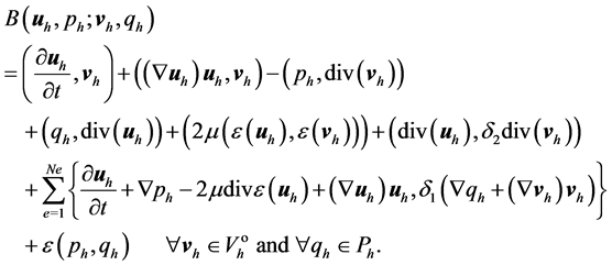
With ![]() and the usual finite element method stabilizing parameters [10] given by
and the usual finite element method stabilizing parameters [10] given by

where he is the element diameter, the local Reynolds number, Reh, is given as

The time discretization has been carried out by the usual backward Euler finite difference.
4. Original Project and Modifications
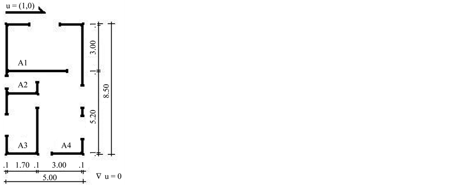
In this study, the case analysed consists of the evaluation of the possible interference suffered by indoor wind field of one prototype of a residence module, drawn in Figure 1(a), starting from the change of location and shape of obstacles in the neighbourhood of the building environment. The module is composed by four indoor areas: A1, A2, A3 and A4.
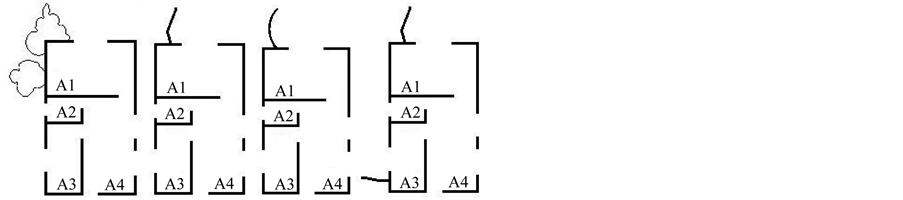
These modifications, through the location of distinct obstacles, seek to promote an alteration in the indoor air circulation. In the plants illustrated in Figures 2 and 3, the outdoor obstacles can be observed with forms and varied positions inserted in the neighbourhood of the original module. To allow more rapid identification each plant received a name and number, such as Plan 1, Plan 2 etc. The four placed plants corresponding to letters (a), (b), (c) and (d) of each figure present the situations in which obstacles are located on the right side of the construction, and the four located plants corresponding to letters (e), (f), (g) and (h) of each figure show the situa-
 (a)
(a) (b)
(b)
Figure 1. (a) Original plan and (b) Original plan—whole mesh.
 (a) (b) (c) (d)
Figure 2. Outdoor obstacles to the original module—right side: (a) Plan 1, (b) Plan 2, (c) Plan 3 and (d) Plan 4.
 (a) (b) (c) (d)
Figure 3. Outdoor obstacles to the original module—left side: (a) Plan 1a; (b) Plan 2a; (c) Plan 3a and (d) Plan 4a.
tion in which the obstacles are located on the left side of the construction. The obstacles possess irregular form in the plants Plan 1 and Plan 1a, angular form in Plan 2 and Plan 2a, curved form in Plan 3 and Plan 3a and two angular obstacles can be observed in Plan 4 and Plan 4a.
The variation of the performance of indoor air circulation, as a result of outside changes, is an expectation since the importance of interference of obstacle location in areas neighboring the building environment are know.
5. Simulations and Results
In the case of countries in which a great part of the population is poor and has not enough money to maintain monthly energy costs, the application of passive strategies in ventilation may allow for the achievement of a higher quality of life in their own homes, by promoting better ventilation and therefore a more pleasant environment. In this work the interventions suggested were of simple construction and low financial and environmental cost. These factors are more relevant in today’s world.
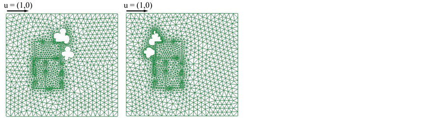
These modifications have been carried out to provide an improved plan for the air circulation inside the original module, by simply altering the neighborhood of the building environment using an easy and economical alternative. In the illustration of Figure 1(a), the arrows indicate the direction of the outdoor wind, providing the boundary conditions. The adopted absolute value of this wind was 1 m/s, according to the Beaufort Scale, used in time forecast, corresponding to the breeze. The dimensions of the rooms are indicated in Figure 1(a). The meshes and results for each case are presented in Figures 4 and 5, for the plan areas. For all the cases, the whole mesh comprises an area of 20 × 18.50 m2 (see Figure 1(b)), which is larger than the area of the plans, to impose the boundary conditions on their borders and to leave the unknown velocities at the openings that are determined by the solution of the problem.
The numerical solutions for the mathematical model were obtained by a stabilized mixed finite element method, as shown in Section 3, Finite Element Formulation. Subroutines in Fortran language, based on the one DLearn by T. J. R. Hughes [11], were developed for the computational simulation.
The results are presented in terms of velocity vector fields in m/s and contour fill of |u|.
6. Comparison of All the Plans
All the cases were compared to the original reference plan by the following criterion. We introduce a global
 (a)
(a)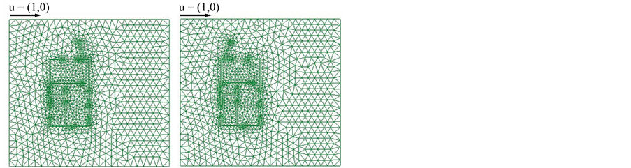 (b)
(b)
Figure 4. Whole mesh—Plan 1 (a), Plan 1a (b), Plan 2 (c) and Plan 2a (d).
 (a)
(a)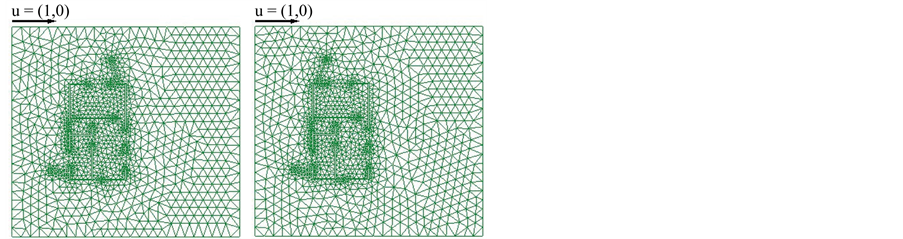 (b)
(b)
Figure 5. Whole mesh—Plan 3 (a), Plan 3a (b), Plan 4 (c) and Plan 4a (d).
circulation index  [7], defined for each plan
 ![]() as
as

where, ![]() is the reference value defined by the user and taking into account the strip of ventilation of interest for analysis,
is the reference value defined by the user and taking into account the strip of ventilation of interest for analysis,  s the partial area of room i with absolute velocities higher than the determined reference value
![]() ,
,  s the total area of room i and
 ![]() s the total number of rooms in the plan.
s the total number of rooms in the plan.
This  index is used to estimate the global circulation increase or decrease in each Plan
![]() , and by comparing these values among all the plans the best case for each situation has been selected. Furthermore, the cases for velocity strips between two values of
, and by comparing these values among all the plans the best case for each situation has been selected. Furthermore, the cases for velocity strips between two values of ![]() can also be appraised.
can also be appraised.
It is interesting to observe that these results can be applied to different wind strips, represented by color scales in this study, which allows the user to select the strip of interest for analysis. The four values of wind velocity in Table 1 (adapted from Evans [12]), namely, 0.25 m/s, 0.50 m/s, 1.00 m/s, and 1.50 m/s, were selected as a reference for our analysis. In Table 1, the values of wind velocity, in m/s, are associated with the effects of the building environment ventilation.
The results obtained through computational simulation for this group of nine plans with external obstacles are illustrated in Figures 6-10 in terms of velocity vector fields and contour fill of . They are shown seeking to assist four situations presented in Table 1, or are, 0.25 m/s, 0.50 m/s, 1.00 m/s, and 1.50 m/s. They can be verified in Figure 8 for
 , in Figure 9 for
 , in Figure 10 for the located values between 1.00 and 1.50 m/s, presented in yellow, and in brown for
 .
.
From the observation of the results, it can be verified that the modifications imposed outdoors, through the introduction of the external obstacles, with diferent shapes and locations, resulted in alterations of the indoor wind-fields. The redirection of the indoor wind-fields was occured even in the places where the openings did not received the direct interference of the location of these external obstacles. In these cases, the dynamic’s of air circulation within the connected spaces was able to impose changes on the whole module, thereby, producing alterations even to the indoor areas that were not directly related to the obstacles.
The percentile values obtained through the global circulation index  for the four strips of
  selected, are presented in Tables 2-5. Comments related to those observed in the tables and illustrations are presented at the end of this section.


Figure 6. Wind field—Plans 1 (a); 2 (b); 3 (c); 4 (d); 1a (e); 2a (f); 3a (g) and 4a (h).
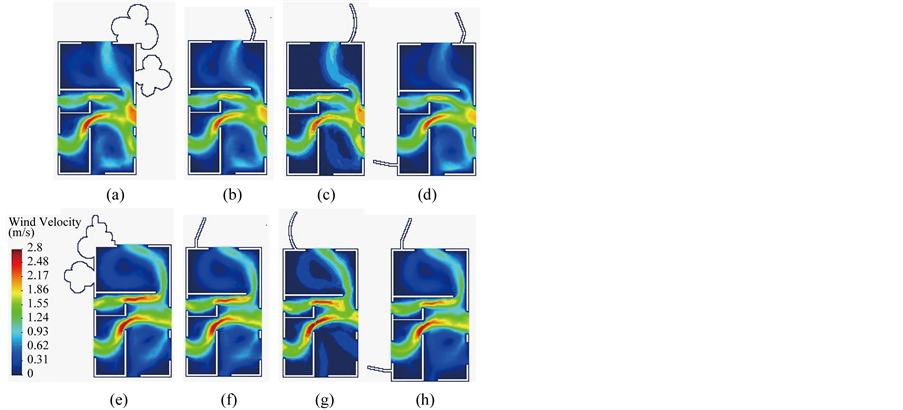
Figure 7. Contour fill of |u|—Plans 1 (a); 2 (b); 3 (c); 4 (d); 1a (e); 2a (f); 3a (g) and 4a (h).
These results seem encouraging since they have indicated the possibility of modifying the behavior of indoor ventilation through simple changes imposed on outside spaces, thus confirming the connection between indoor and outdoor environments.
The application of passive strategies may allow for the achievement of an elevated quality of the indoor environment even working with low financial and environmental cost. The use of natural ventilation for cooling is maybe one of the ways to work with low cost solutions and to promote indoor air cooling even in poor regions.
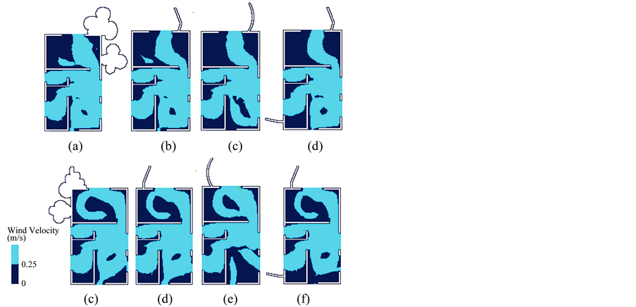
Figure 8. —Plans 1 (a); 2 (b); 3 (c); 4 (d); 1a (e); 2a (f); 3a (g) and 4a (h).
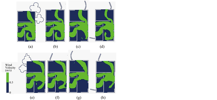
Figure 9. —Plans 1 (a); 2 (b); 3 (c); 4 (d); 1a (e); 2a (f); 3a (g) and 4a (h).
It is also of note that these alternatives allow users of the spaces to have control of openings, therefore, regulate ventilation when necessary.
This aspect is relevant when taking into account that some poor countries are located in hot climate regions and their population has not enough money to install equipament and maintain monthly energy costs.
7. Conclusions and Remarks
From the results, it was possible to infer the interference of external volumes to the module in the acting of the indoor air ventilation. These obstacles worked as screens and redirected the wind field, interfering in its distribution and intensity. The influence of the microclimate in the quality of indoor building environments has been determined, and the experiments confirmed its use as a passive strategy of ventilation, landscape not withstanding out, and thus, as an element capable of interfering actively in the indoor dynamics.
The alterations of air circulation in indoor spaces, as mentioned earlier, do occur even when the openings of those spaces are not placed in the proximity of the obstacles.
From Table 2, it was possible to verify that the located obstacles to the left of the superior opening were

Figure 10. 1.00 ≤ Vr ≤ 1.50 m/s—Plans 1 (a); 2 (b); 3 (c); 4 (d); 1a (e); 2a (f); 3a (g) and 4a (h).

Table 2. Evaluation of indoor ventilation according to the (KD)G for Vr ≥ 0.25 m/s, corresponding to Figure 8.
Table 3. Evaluation of indoor ventilation according to the (KD)G for Vr ≥ 0.50 m/s, corresponding to Figure 9.
Table 4. Evaluation of indoor ventilation according to the (KD)G for 1.00 ≤ Vr ≤ 1.50 m/s, corresponding to Figure 10.
Table 5. Evaluation of indoor ventilation according to the (KD)G for Vr ≥ 1.50 m/s, corresponding to Figure 10.
capable of producing a better distribution of the wind field in room A1 (Figure 1(a)). The displacement of the obstacles to the right was produced positive results in room A4, and at the same time, was reduced the ventilation in room A1, when compared to the previous instance. The same results were observed for  m/s with regard to room A4 (see Table 3).
It is interesting to point out that the welcome increase in ventilation caused by the outdoor obstacles presented in this study also caused an increase in the area with undesirable winds, mainly in room A4. It is important to observe that, in this work, the criterion of undesirable winds, was based on the table about the effects of ventilation in the indoor environment, adapted from the Table of Evans [12]. The definition of the criterion of undesirable wind is also related to the discomfort caused by slamming of doors and the displacement of light weight objects, such as papers. Some authors may have other definition about strips of wind and even inhabitants of hot regions like Rio de Janeiro city, which could often prefer a strong wind with their undesirable consequences because in high temperatures it would be improving the thermal sensation.
Again, these observations demonstrate the importance of adaptation between the interest and the users’ space needs and project decisions. For instance, in the plans Plan 1a, Plan 2a, Plan 3a and Plan 4a of Figure 8, in which the obstacles are located to the left of the construction, the room A1 presented ventilation earnings in interesting strips of wind, and practically, did not present areas with undesirable winds. The increase in the areas with undesirable winds should be considered as a reasonable price to pay when considering the benefits of environmental refreshment and cooling in the indoor area as a whole.
Therefore, it is important to perform studies related to the urban occupation and ventilation for both placement of new cities or even for intervention in existent neighbourhoods. Urban morphologies are able to determine the barriers impairing the passage of winds, but may also design strategies making possible to redirect winds contributing to the environmental comfort of the users of urban spaces.
The computational simulation is an important tool to aid design decisions. It allows the evaluation of different configurations still in the design phase, both in urban and architectural models. This is an important factor in reducing design flaws resulting in reduced financial and environmental costs. In this work the interventions suggested were of simple construction and low financial and environmental cost. These factors are more relevant in today’s world.
Acknowledgements
Patricia R. C. Drach thanks the support of the FAPERJ (State of Rio de Janeiro research supporting foundation) and the Conselho Nacional de Desenvolvimento Científico e Tecnológico—CNPq (National Council for Scientific and Technological Development), Brasil. J. Karam-Filho would like to acknowledge PRONEX/ FAPERJ project No. E-26/171.199/2003.
REFERENCES
- O. D. Corbella and S. Yannas, “Em Busca de Arquitetura Sustentável para os Trópicos,” Editora Revan, Rio de Janeiro, 2003.
- B. Givoni, “Man, Climate and Architecture,” Applied Science Publishers LTD, London, 1976.
- L. R. Mascaró, “Clima, Arquitetura e Energia,” Proceedings of the Seminário de Arquitetura Bioclimática, Rio de Janeiro, 1983, pp. 11-17.
- R. Lamberts, L. Dutra and F. O. R. Pereira, “Eficiência Energética na Arquitetura,” Editora PW, São Paulo, 1997.
- S. Szokolay, “Approaches to Tropical House Design,” Proceedings of the II Encontro Latino Americano de Conforto no Ambiente Construído, Fortaleza, 1999.
- P. R. C. Drach and J. Karam-Filho, “Análise de Circulação de ar em Ambientes Interiores, via Elementos Finitos,” Proceedings of the I—Latin American Conference on Sustainable Building and X-Brazilian Conference on Technology for the Building Environment, São Paulo, 18-21 July 2004, pp. 1-14.
- P. R. C. Drach and J. Karam-Filho, “Effects of Wall Shape Changes in Indoor Air Circulation—Studies on Concave and Convex Walls,” International Journal of Ventilation, Vol. 9, 2010, pp. 149-161.
- A. N. Brooks and T. J. R. Hughes, “Streamline Upwind/Petrov-Galerkin Formulations for Convection Dominated Flows with Particular Enphasis on the Incompressible Navier-Stokes Equations,” Computer Methods in Applied Mechanics Engineering, Vol. 32, No. 1-3, 1982, pp. 199-259. http://dx.doi.org/10.1016/0045-7825(82)90071-8
- J. Karam-Filho and A. F. D. Loula, “On Stable Equal-Order Finite Element Formulations for Incompressible Flow Problems,” International Journal for Numerical Methods in Engineering, Vol. 2, No. 34, 1992, pp. 655-665. http://dx.doi.org/10.1002/nme.1620340216
- L. P. Franca and S. L. Frey, “Stabilized Finite Element Methods: II. The Incompressible Navier-Stokes Equations,” Computer Methods in Applied Mechanics Engineering, Vol. 99, No. 2-3, 1992, pp. 209-233. http://dx.doi.org/10.1016/0045-7825(92)90041-H
- T. J. R. Hughes, “The Finite Element Method: Linear Static and Dynamic Finite Element Analysis,” Prentice-Hall, Inc., Englewood Cliffs, New Jersey, 1987.
- J. M. Evans, “Housing, Climate and Comfort,” Architectural Press LTD, London, 1980.