Smart Grid and Renewable Energy
Vol.4 No.2(2013), Article ID:32192,10 pages DOI:10.4236/sgre.2013.42027
Sizing and Design of the PV-WIND Energy Dryer for Medical Herbs
![]()
PV Cells Department, Electronics Research Institute, Cairo, Egypt.
Email: emadsweelem@yahoo.com, abdelshafyn@yahoo.com, fatenhf@yahoo.com
Copyright © 2013 Emad Ahmed Sweelem et al. This is an open access article distributed under the Creative Commons Attribution License, which permits unrestricted use, distribution, and reproduction in any medium, provided the original work is properly cited.
Received December 18th, 2012; revised January 18th, 2013; accepted January 25th, 2013
Keywords: Medical Herbs Dryer; Solar Thermal System; Renewable Energy
ABSTRACT
Medical herbs are located in Egypt in different areas and they are very important to increase the national income of Egypt. It is necessary to dry the herbs in their growing locations. As the growing locations are located far from the natural supply grid of Egypt, renewable energy sources such as PV&WIND are preferably utilized to achieve the drying process. Moreover, since the drying process is actually used to remove water from the herbs, thus it can preserve the herbs in storage drastically by preventing the attack of microorganisms during the moist conditions of herbs and also reduce their weight and bulk (for cheaper transport). Where, this paper selects, at first, the suitable drying site, and then it suggests. The suggested drying system is completely designed, and includes the following three systems: the solar thermal system, the dryer, and the renewable energy system.
1. Introduction
Drying is used to remove water from herbs for two reasons: to prevent (or inhibit) microorganisms and hence preserve the product and to reduce the weight and bulk of herb for cheaper transport and storage. If drying is carried out incorrectly there is a greater loss of nutritional and qualities and more seriously, a risk of microbial spoilage. Therefore, we will describe some of the requirements for proper drying and summarize information on the various available drying techniques.
Drying can be carried out using hot air. For effective drying, air should be HOT, DRY and MOVING. These factors are inter-related and it is important that each factor is correct (for example, cold moving air or hot wet moving air are each unsatisfactory) [1].
2. Common Herb Drying Methods
Drying is the most critical operation in the production of medical herbs. Herbs can be dehydrated by various means: room drying, a conventional oven, a microwave oven or a dehydrator [2].
2.1. Room Drying
This method of drying differs from sun drying since it takes place indoors in a well-ventilated attic, room, car, camper or screened-in-porch. Herbs can be strung on a string or tied in bundles and suspended from overhead racks in the air until dry. Enclosing them in paper bags, with openings for air circulation, protects them from dust, and other pollutants. This method of drying is inefficient, takes long time (11 - 14 days) and produces low quality dried products [3].
2.2. Oven Drying
This method is the most practical way to experiment with dehydration. It protects herbs from insects and dust, and does not depend on the weather (flowers, dry well in a fan-assisted, convection oven). Non-ventilated ovens are not appropriate, because they generate too much moisture. The flowers are slotted through holes in a wire mesh rack leaving room for the stems to dangle below. The time required depends upon the density of the flowers [4].
Continual use of an oven for drying is not recommended because ovens are less energy efficient than dehydrators, and energy costs tend to be high. Also, it is difficult to maintain a low drying temperature in the oven, and herbs are more susceptible to scorching at the end of the drying period. Oven-dried herbs usually are darker, more brittle and less flavorful than herbs dried by a dehydrator. Moreover, drying herbs in the oven causes water oils in the herb to evaporate too quickly that way. For oven drying, fresh herbs are placed in a single layer on the racks [5].
2.3. Microwave Oven
Drying herbs in a microwave is quick, simple, and gives excellent results. Two layers of paper towel are placed in the bottom of the microwave. Then a layer of herbs is added and covered with two more layers of paper towel. The microwave is run for two or more than two minuets until the herbs are dried. This method of drying can be used only in a small scale. It also requires careful attention, as the paper towels in the microwave can catch fire if hot spots occur [6].
2.4. Herbs Dryers
Herbs can be dried on trays in a dehydrator. Although the initial investment is fairly high for a dehydrator, it maintains low temperatures and uses less energy than an oven. The quality of the product is better than with any other method of drying. As with oven drying, there is no dependence on weather conditions [7].
Types of Herb Dehydrators (Dryers)
1) Firewood/fuel dryer This technique uses fuel source to create the required heat for drying. It is quicker than open air-drying, but it requires investment in fuel. The dried product may be affected with smoke and easily degrades [8].
2) Solar thermal AC powered dryer This type has bigger size and is usually made for heavy-duty. It is supplied by fan to circulate the hot air inside the dryer. The heating energy is provided by the sun collector. During the utilization of this type in rural areas, the air circulation fans and the pumps can be powered using DC source [9].
3) Solar thermal photovoltaic (PV) powered dryer This dryer is called solar tunnel dryer. It had been used for drying rosemary and thyme plants produced in Thailand in 1999. The quality parameters of the dried products were selected on the basis of internationally recognized standards for dried spices and medical plants and include colour assessment, ash content, essential oil and oleoresin content and composition with regard to the important active components, cineole in rosemary and thymol in thyme. The colour preservation of dried rosemary and thyme was best achieved with the solar tray dryer [10].
3. Sizing and Design of the Suggested Renewable Energy Dryer
In this section the configuration of the suggested medicinal herb dryer system is presented. Also, a complete design and sizing for the different components of the proposed system is carried out in details.
3.1. Configuration of the Suggested Herb Dryer
The configuration of the suggested medicinal herb dryer system is shown in Figure 1. The diagram consists of three main systems: the solar thermal system, the dryer, and the renewable energy system. The main function of the solar thermal system is to supply the inlet air to the dryer with the required solar thermal energy that is suitable to accomplish the drying process. While, that of the renewable energy system is to feed the electrical load of the dryer with the required electrical energy, to ensure good and continuous drying operation.
3.2. Design of the Dryer and the Solar Thermal System
In this section the complete design steps of the proposed herb dryer and its associated solar thermal system is carried out. Where, the solar thermal system, which is responsible for heating the drying air, consists mainly of three components; which are the solar collector, the stor-

Figure 1. The medicinal herb dryer system.
age tank, and the heat exchanger.
3.2.1. The Dryer Design
The dryer design includes designing the different parameters that significantly influence the dryer performance. The dryer is designed as a cylindrical (bin) type with an inlet and outlet ducts (Figure 2). This type of dryer is ideally suited for drying medicinal herbs, since it is suitable for low temperature operation. The inlet duct is equipped with a blower, heat exchanger, and an electrical heater; to heat the inlet drying air. While, the outlet duct has four windows, to constitute four exits for the drying air after passing on the herb in the drying chamber. The dimensions of the drying chamber are 130 cm (diameter) × 50 cm (height). There are five wire mesh trays fixed one over the other inside the drying chamber for putting the herb to be dried. The trays are designed to distribute the air such that it follows a longer zigzag route, which increases the air/herb contact time and thus increases the drying efficiency. It is noted that a dark drying chamber is needed in order to isolate sunlight, which has a load effect on the herb. To achieve this purpose, the inner surface of the drying chamber is isolated with thin film of aluminum oxide foil.
1) The energy balance and temperature for drying If unsaturated air is passed over wet material the air will take up water from the material. This water has to be evaporated, and the heat to do this comes from the air and the material. This air is thereby cooled. In particular, if a volume Vair of air is cooled from an initial temperature Ti to a final temperature Tf in the process of evaporating a mass mw of water, then by applying the energy balance principle on the drying process, yields [11]
 (1)
(1)
where mw could be calculated from the following equation [11]
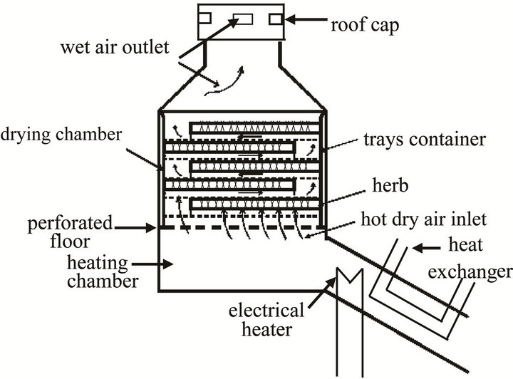
Figure 2. The designed herb dryer.
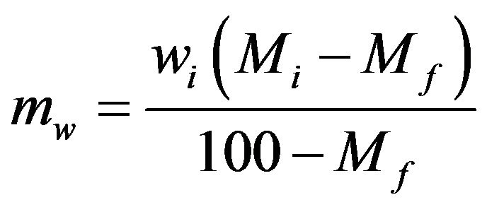 (2)
(2)
where:
mw mass of water evaporated from the herb (kg);
mair mass of the used drying air (kg), which absorbs mw;
L the specific latent heat of vaporization of the water from the herb (=2.4 MJ/kg);
CPair specific heat capacity of air at constant pressure (=1.005 kJ/kg ˚K);
Ti initial temperature of the drying air (˚C);
Tf final temperature of the drying air (˚C);
wi initial mass of wet herb (kg);
Mi initial moisture content of the herb (%);
Mf final moisture content of the herb (%).
In this design, it is assumed that 20 kg of Henbane, as one of the Sinai Peninsula (i.e., Abu Rudies) medical herbs, wanted to be dried in 22 h. Where, the remaining two hours of the day are left for accomplishing the predrying process of the herbs and are chosen to be in the early morning; since gathering the herbs to be dried must be after the dew has evaporated, to minimize wilting of herbs. Then using the data of the annual average ambient temperature of Abu Rudies is 23.15˚C and the corresponding relative humidity is 57%.
The suitable initial air temperature Ti for drying of medicinal herbs may range from 35˚C to 45˚C, but it is found that the optimal drying temperature for most of the medicinal herbs is about 40˚C [2].
The final temperature of the moist drying air that leaves the dryer can be found from the Psychometric chart of Figure 3 [12] as follows: the ambient air before entering the drying chamber corresponds to point A of Figure 3 (i.e., its temperature is 23.15˚C and its relative humidity is 57%).
If the small change in the density of the drying air is neglected under heating it from the ambient temperature of 23.15˚C to 40˚C, then point A of Figure 3 will shift horizontally to point B (that has the same absolute humidity as point A). Note that the relative humidity of point B is lower than that of point A. After passing through the herb in the dryer, the exit air from the dryer will be cooled and becomes more moist, and this is corresponds to moving from point B to point C of Figure 3 [12] (i.e., Tf = 22.5˚C).
Since, the Henbane herb has Mi = 75% and Mf = 14%, then using Equations (4), (5) give mw = 11.74 kg & mair = 1602.047 kg. Thus, the required mass flow rate to accomplish the drying process of Henbane in the specified time is
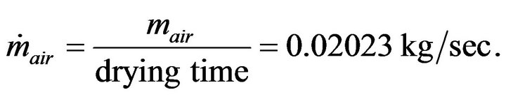 (3)
(3)

Figure 3. Psychometric chart (for standard air pressure of 101.3 kPa).
where, the volume of air needed for one drying cycle is given by
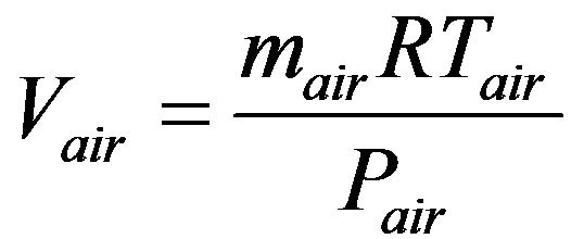 (4)
(4)
where:
R the characteristic gas constant (=0.287 kJ/kg˚K);
Tair ambient temperature (=23.15˚C = 296.15˚K);
Pair air pressure (=101.3 kN/m2 or kPa);
Therefore, Vair = 1344.2 m3 and the corresponding volume flow rate .
.
2) Coefficient of performance of the designed dryer (COP)
The performance coefficient of the dryer is defined as the ratio of the quantity of heat required evaporating the moisture content of the dried herb and the amount of heat to be supplied to the dryer, and is given by [2]
 (5)
(5)
The overall thermal efficiency of the dryer is defined as the ratio of the quantity of heat required evaporating the moisture content of the dried herb and the solar energy incident on the plane of the solar collector, and is given by [13]
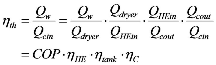 (6)
(6)
Assuming hHE = 0.9, htank @ 1, and hc = 0.75, gives hth = 0.7.
3.2.2. Design of the Solar Thermal System
In this work, the solar thermal system consists of a flatplate solar collector, a vertical storage tank, and a heat exchanger.
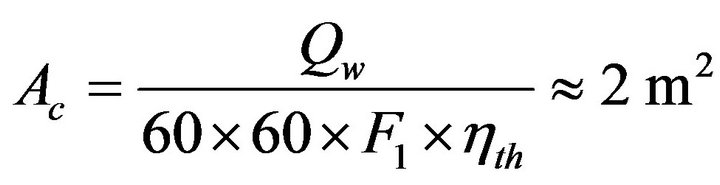
1) The flat-plate collector The flat-plate collector consists basically of an absorbing surface, an insulation layer, anodized aluminum section casing and a transparent cover (Figure 4). The collector area Ac can be computed from
 (7)
(7)
where, F1 is as defined before, to be the global solar radiation in kW·h/m2/day (of abu Radis) incident on a south facing plane, which is tilted to the horizontal by the latitude angle. Therefore, the collector is designed to have a 2 m length and 1 m width. The absorbing surface is made of aluminum. It is painted by a black color, and insulated from bottom and sides by 4 cm polyurethane insulation layer to reduce heat losses to the surroundings. Also to minimize the heat losses from the upper collector surface due to the re-radiation and convection, an absorber plate is provided with a transparent cover. This cover must be capable to transmit almost all solar radiation as possible. A glass sheet with 3 mm thickness is fixed 3 cm above the absorber.
2) The storage tank The designed storage tank consists of a steel cylindrical vessel of 44.6 cm diameter and 132 cm height (Figure 5). It’s insulated by a layer of 7 cm of glass wool and the other casing cover is aluminum.
3) The heat exchanger The used heat exchanger is a parallel flow water to air type, which consists of two concentric pipes of different diameters (Figure 6). The hot fluid (i.e., the water) passes inside the smaller diameter pipe, while the cold fluid (the

Figure 4. Description of the flat-plate collector.
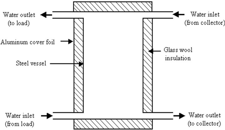
Figure 5. The storage tank.
air) passes through the space between the two pipes.
3.3. Sizing of the Suggested Renewable Energy System
In this section the complete sizing of the proposed renewable energy system and its electrical load is carried out. Where, the renewable energy system, which is responsible for supplying the electrical load of the dryer with the required electrical power, consists mainly of three components; which are the photovoltaic (PV) array, the wind generator, and the storage battery.
3.3.1. Dryer Electrical Load
As the electrical load profile can be constructed from the suggested load data, and since the load data define all the information about the suggested electrical load (i.e., number of equipments to be powered, their nominal power, system voltage, and the number of hours of operation for each equipment in a typical day). Figure 6 shows the dryer electrical load, which consists of the following equipments: the signal lamp, the electrical heater, the blower, two valves and two pumps. These equipments constitute a typical load for the designed dryer. The data of the suggested load are illustrated in Table 1, which imply the dryer load profile of Figure 7. It is to be noted, here, that the drying process is achieved using the designed dryer in 22 h only of the day, while the remaining two hours are left for accomplishing the predrying process of the herbs and are chosen to be in the early morning (since gathering the herbs to be dried must be after the dew has evaporated, to minimize wilting of herbs).
3.3.2. Optimization Sizing of PV-Wind-Battery Hybrid Energy System
The dependence on energy resources, which are expensive and in the long run extinguishable, has led recently to an increased interest in harnessing renewable energy resources. Whether electricity generation uses conventional or renewable sources, it should have a unique function that is to continuously supply the load in the most economic way.
As can be concluded from the above, of the main concern in the design of an electric power system that utilizes renewable energy sources is the accurate selection of system components that can economically satisfy the load demand. In this section, the most economical design of an autonomous renewable energy system composed of solar, wind, and battery sets is determined using Homer Software [14].
1) Formulating the problem The task of the optimization technique is to determine the size of each component participating in the system so that the load can be economically satisfied. For this reason, the control variables are made to represent either
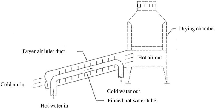
Figure 6. Schematic diagram of heat exchanger.
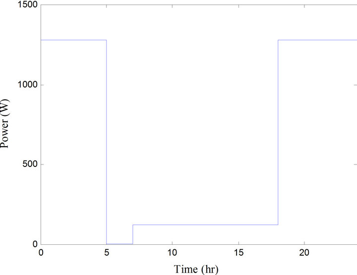
Figure 7. Typical daily load profile of the dryer.
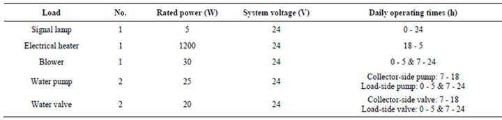
Table 1. Electrical load data of the dryer.
size or rating of system components. The objective function to be minimized is the cost of producing one kilowatt-hour of electricity, and the constraints are expressed through load requirements.
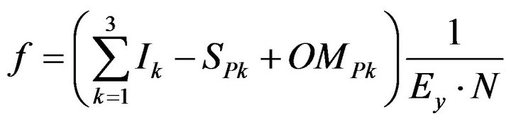
The cost function is generated by dividing the summation of the present worth of all the salvage values of the equipment, the yearly operation and maintenance costs and the initial or capital investments, by the expected energy demand which is supplied during the lifetime of the project. The cost function can be written as [15]:
 (8)
(8)
where: the index k is made to account for wind, solar, diesel generators and batteries; Ik is the initial investment for each component k; SPk is the present worth of the salvage value of each component k; OMPk is the present worth of the operation and maintenance costs for each component k; Ey is the yearly energy demand; and N is the lifetime of the project.
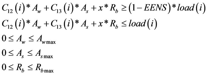
The constraints that ought to be met, while minimizing the objective function, should ensure that the load is served according to certain reliability criteria. The extent of system reliability is measured by the expected energy not served (EENS) within each sub period of operation. This value should be specified by the designer in view of the priority of the load and the adopted pricing strategy. The constraints can now be written as:
 (9)
(9)
For all the sub periods i, where Ek(i) is the energy from source k during sub period i; and Load(i) is the energy demand during sub period i.
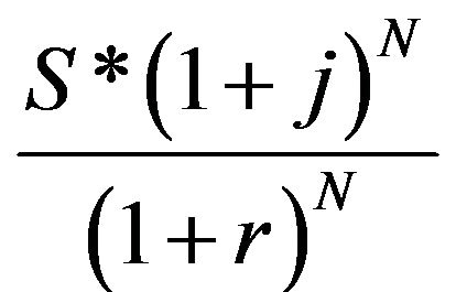
2) Basic economical considerations As Equation (8) suggests, the present worth of some annual payments as well as of salvage values are needed. Assuming a life horizon of N years, an interest rate r, and an inflation j caused by increases in price, the following can be noted.
a) If a component has a salvage value of S($) at present because it is reaching the end of its life cycle, then the salvage value is expected to be S·(1 + j)N, N years from now provided that the component is put in service at the present. The present value of S·(1 + j)N taking the interest rate into consideration is [16]:
 (10)
(10)
Let , then SPk = Sk * facl for all components k in the system.
b) If the operating and maintenance cost of a component is OM ($·year–1), then this tends to escalate each year at a rate not necessarily equal to the general inflation. With an escalation rate “es”, the operation and maintenance costs incurred at year “y” will be OM * (1 + es)y having a present worth of
 (11)
(11)
The summation of the present worth of all the annual payments is given by
 (12)
(12)
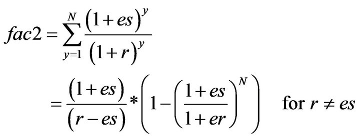 (13)
(13)
Thus, fac2 = N if r = es. Hence OMPk = OMk * fac2, for all components, “k” in the system. At this stage it is worth mentioning that the power extracted from the wind and solar systems are calculated using the following models.
3) Wind system A wind turbine generator (WTG) produces power when the wind speed V is higher than the cut-in speed Vci and is shut-down when V is higher than the cut-out speed Vco, when Vr < V < Vco, (Vr is the rated wind speed), the WTG produces rated power “Pr”. If Vci < V < Vco the WTG output power varies according to the cube law. The following equations are to be used in order to model the WTG in the optimization:
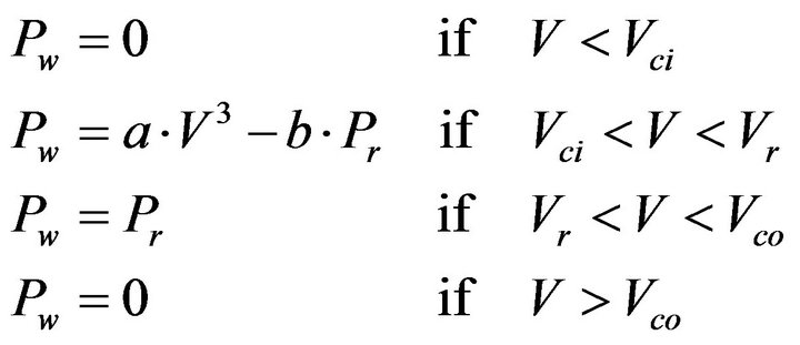 (14)
(14)
where
 (15)
(15)
And
 (16)
(16)
In the above, Cp = 0.3, r = 1.2 Kg·m–3 at 20˚C.
Efficiency of solar system (effs) = 0.3, Inflation rate (j) = 0.09, Interest rate (r) = 0.12Escalation rate (es) = 0.09, Project life span (N) = 30 years, Annual real interest rate (r) = 10%;
Battery life span (Lb) = 10 years, Experted energy not served (EENS) = 1%, Solar panel salvage value (ss) = 45 $$/m2, Wind turbine salvage value (sw) = 10 $/m2, Diesel engine salvage value (sd) = 80 $/Kw, Load = see Figure 7.
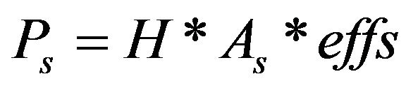
4) Solar system For a photovoltaic array having an efficiency “effs” and area “As”, the output power “Ps” (kW) when subjected to a horizontal irradiance H (kW·m2) is given by
5) Optimization coefficients a) Wind turbine The control variable due to the wind turbine is the total rotor area Aw in square meters. This value is constrained by both the space available and the budget of the project. Numerically, Aw is generated through linear programming, though it is the task of the designer to distribute Aw among several machines.
Given αw, the initial price per square meter of the wind turbine, the term I1 of Equation (16) that corresponds to the total initial price of the wind machines is equal to αw × Aw. It should be noted that if the price in $/kW is available rather than αw then αw can be generated by finding how many kilowatts the wind machine can generate per square meter at rated wind speed and multiplying this number by the cost per kilowatt.
With a salvage value of Sw ($·m–2), the total salvage value would be S1 = Sw * Aw and the present worth
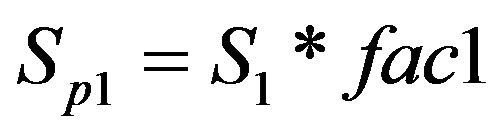 (16)
(16)
Finally, with a yearly operation and maintenance cost of αOMW per square meter ($·m–2·year–1), the total yearly operation and maintenance cost would be OM1 = αOMW * Aw, and the present worth of all the yearly costs would be:
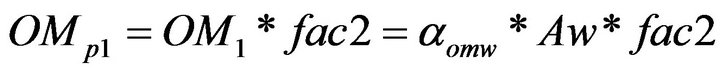 (17)
(17)
If the operation and maintenance cost is given in dollars per kilowatt per year, this value should be multiplied by the number of kilowatts generated per square meter at rated wind speed to obtain αOMW. As a summary for wind turbines, we have
 (18)
(18)
b) Solar panels Solar arrays can be treated following the approach used for wind rotors. The control variable is the total solar panel area as in square meters and is constrained by both the maximum available area for solar panels (for example the roof surface of buildings) and the budget preset for the panels.
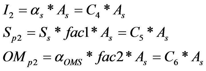
With an initial cost of αs ($·m–2), the total initial investment would be I2 = αsAs. The salvage value can be found by multiplying the selling price per square meter Ss by the area As and the present worth of the selling price would be
 (19)
(19)
With a yearly operation and maintenance cost of αOMS per square meter ($·m–2·year–1), the total yearly operation and maintenance cost would be OM2 = αOMS as with a global present worth of:
 (20)
(20)
As a summary for solar panels, we have
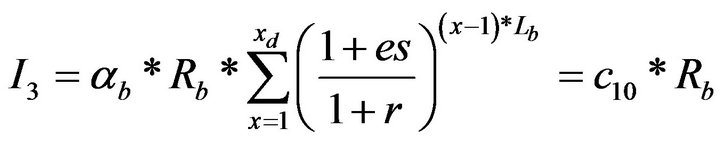
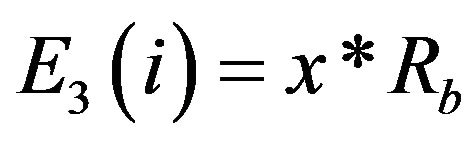
c) Storage batteries The control variable in the case of storage batteries is their size Rb in kilowatt-hours. The lifetime of a battery (Lb) is expected to be less than that of the whole project. Hence batteries of size Rb are to be purchased at regular intervals of Lb. The total present worth of the capital investment in batteries is given by
 (21)
(21)
where Lb, is the battery lifetime, xb is the number of times batteries should be purchased during the project lifetime: xb = N/Lb rounded to the greatest integer, and αb is the capital cost of 1 kWh storage ($·kW·h–1).
The salvage value of the batteries is assumed negligable. With an operation and maintenance cost of αOMB ($·kW·h–1·year–1), the total yearly OM cost would be OM4 = αOMB * Rb with a global present worth of
 (22)
(22)
In summary, the battery charges can be represented by

6) Load constraints The constraints on the optimization problem were expressed through Equation (12). Let ew(i) and es(i) represent the wind and solar energy, respectively, available during sub period “i” per square meter, and let the energy generated by the diesel generator be Rd times the duration of the sub period. The elements of the constraints can then be formulated as:
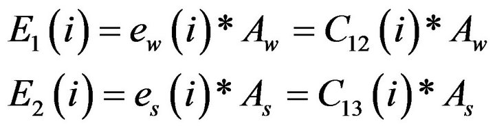 (23)
(23)
 where x is the fraction of the battery capacity expected to discharge in each sub period. This implies that for each sub period i, the following should be satisfied:
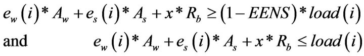 (24)
(24)
Additional constraints should be imposed on the size of the system components:
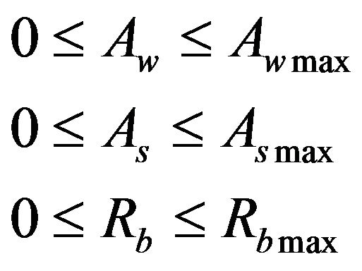 (25)
(25)
7) Final form At this stage, the optimization problem can be written in its final form as follows:
a) Minimize the cost function f:

b) Subject to:
8) Results of the sizing of the renewable energy system In this part the results of applying optimization program are displayed as shown in Table 2.
4. Conclusions
The suggested drying system is completely designed, and includes the following three systems: the solar thermal system, the dryer, and the renewable energy system. The main function of the solar thermal system is to supply the dryer inlet air with the required thermal energy through utilizing the flat plate solar collector. While, that of the renewable energy system, which comprises hybrid photovoltaic and wind energy sources, is to feed the electrical load of the dryer with the required electrical energy.
The general principles of wind power and solar energy together with its two parts (solar thermal collectors and solar photovoltaic energy) are discussed and evaluated in details from different viewpoints. Where, Glazed flat-plate

Table 2. Optimization sizing results.
collectors are the common available and suitable collectors for using in herb drying systems. Since, these collectors are better suited for moderate temperature applications where the demand temperature is 30˚C - 70˚C.
REFERENCES
- M. R. Patel, “Wind and Solar Power Systems,” Library and Congress, Washington DC, 1999.
- M. Yahya, K. Sopian, W. R. W. Daud, M. Y. Othman and B. Yatim, “Design of Solar Assisted Dehumidification of Air Drying System for Medicinal Herbs: Pegaga Leaf,” Proceedings of the 2nd Asian-Oceania Drying Conference (ADC 2001), Pulau Pinang, 20-22 August 2001, pp. 383- 392.
- “Effects of Drying on Quality of Rosemary and Thyme Plants Produced in the Chaing Mai District, Thailand,” Master Thesis of Marija Spirovska. http://www.troz.uni-hohenheim.de/research/Thesis/MScFT/Spirovska.pdf
- “Solar Laboratory University of the Philippines, Diliman-, Renewable Energy Technology in Asia, A Regional Research Dissemination Programme Phase II, A Summary of Activities and Achievements in Bangladesh,” Regional Energy Resources Information Center (RERIC), Asian Institute of Technology, Thailand, 2002.
- B. K. Bala, M. R. A. Mondol , B. K. Biswas , B. L. Das Chowdury and S. Janjai , “Solar Drying of Pineapple Using Solar Tunnel Drier,” Journal of Renewable Energy, Vol. 28, No. 2, 2003, pp. 183-190. doi:10.1016/S0960-1481(02)00034-4
- O’Hanian and C. Hans, “Physics,” W. W. Norton & Co., New York, 1985.
- E. W. Brown, “An Introduction to Solar Energy.” http://www.ccs.neu.edu/home/feneric/solar.html.
- T. Markvart, “Solar Electricity,” John Wiley & Sons, Inc., Hoboken, 1994.
- O. V. Ekechukwu and B. Norton, “Review of Solar-Energy Drying Systems II: An Overview of Solar Drying Technology,” Journal of Energy Conversion & Management, Vol. 40, No. 6, 1999, pp. 615-655.
- “Commercialization of the Solar Dryer.” http://www.areed.org/training/technology/solar_dryer dryer_2.pdf
- G. P. Sharma and S. Prasad, “Drying of Garlic Cloves by Microwave-Hot Air Combination,” Journal of Food Engineering, Vol. 50, No. 2, 2001, pp. 99-105. doi:10.1016/S0260-8774(00)00200-4
- www.handsdownsoftware.com
- H. H. El-Ghetany, “Effect of Hot Water Consumption on Temperature Distributions in Vertical and Horizontal Solar Waterv Storage Tanks,” M.Sc.Thesis, Cairo University, Cairo, 1992.
- NREL, “Hybrid Optimization for Electric Renewable Program,” NREL (National Renewable Energy Laboratory), Golden, 2009.
- R. Chedid and Y. Saliba, “Optimization and Control of Autonomous Renewable Energy Systems,” International Journal of Energy Research, Vol. 20, No. 7, 1996, pp. 609-624. doi:10.1002/(SICI)1099-114X(199607)20:7<609::AID-ER176>3.0.CO;2-O
- W. Clark, “Energy for Survival: The Alternative to Extinction,” Anchor Press, Garden City, 1974.