J. Biomedical Science and Engineering, 2010, 3, 47-51
doi:10.4236/jbise.2010.31007 Published Online January 2010 (http://www.SciRP.org/journal/jbise/
JBiSE
).
Published Online January 2010 in SciRes. http://www.scirp.org/journal/jbise
Mobile and wireless technologies applying on
sphygmomanometer and pulsimeter for patients with
pacemaker implementation and other cardiovascular
complications
Ching-Sung Wang
Department of Electronic Engineering Oriental Institute of Technology, Taipei, Taiwan, China.
Emill: ff020@mail.oit.edu.tw
Received 11 August 2009; revised 9 September 2009; accepted 10 September 2009.
ABSTRACT
Continuously monitoring pulse is very important for
the pacemaker patients., and the continuously ob-
serving blood pressure is also a matter of concern for
those who have hypertension, coronary heart disease,
or other cardiovascular diseases, for example cardiac
arrhythmia and hypertension. What we expect is not
only to eliminate arrhythmia, also to treat patients as
a whole of body. Therefore, how to keeping monitor-
ing blood pressure and pulses rise to a very impor-
tant issue. This research edits a wrist-able sphygmo-
manometer and pulsimeter combining with cell
phone, to achieve wireless, continuous, and real-time
observation, early detects any accident occurring
from the patients with pacemaker implementation or
with other cardiovascular complications
Keywords: Pacemaker; Hypertension; Coronary Heart
Disease; Cardiovascular Disease; Sphygmomanometer
and Pulsimeter
1. INTRODUCTION
The population for pacemaker implant is not limited by
age, sex, or race. Over 100,000 pacemakers are impl-
anted per year in the United States. Approximately
500,000 Americans have an implantable permanent
pacemaker device [1]. Pacemaker can be affected by
electromagnetic interference in several different ways,
including temporary inhibition of the pacemaker, tem-
porary function at the fixed noise rate, temporary func-
tion at the fixed magnet rate, permanent inhibition or
malfunction, and random reprogramming. For any of
these results to occur, the E field strength must be
greater than 200V/m or the magnetic field strength must
be greater than 10 Gauss [2].
Cellular telephones can interfere with the function of
implanted cardiac pacemakers [3,4,5]. However, when
telephones are placed over the ear, the normal position,
this interference does not pose a health risk [5]. Barbaro
V, et al. The research of influence between GSM mobile
phone and implanted pacemaker indicates that electro-
magnetic interference effects were detected at a maxi-
mum distance of 10 cm with the pacemaker programmed
at its minimum sensing threshold. When the phone an-
tenna was in direct contact with patient's skin over the
implant, electromagnetic interference effects occurred at
maximum ventricular and a trial sensing thresholds of 4
mV and 2.5 mV, respectively [6]. Therefore, decreasing
wireless emission power and rising pacemaker emission
distance are the most useful methods of lowering the
interference of magnetic to the pacemaker.
In order not to affect users' habits of using mobile and
to avoid the electromagnetic interference effects of pace-
maker, we design a wrist-able sphygmomanometer and
pulsimeter which is using the Bluetooth power class II
[7,8] to be the device for short-distance transmission.
Furthermore, to combine with a cellular phone, we can
do the prolonged distance observation and treatment
immediately for the patients with setting pacemaker or
with other cardiovascular disease.
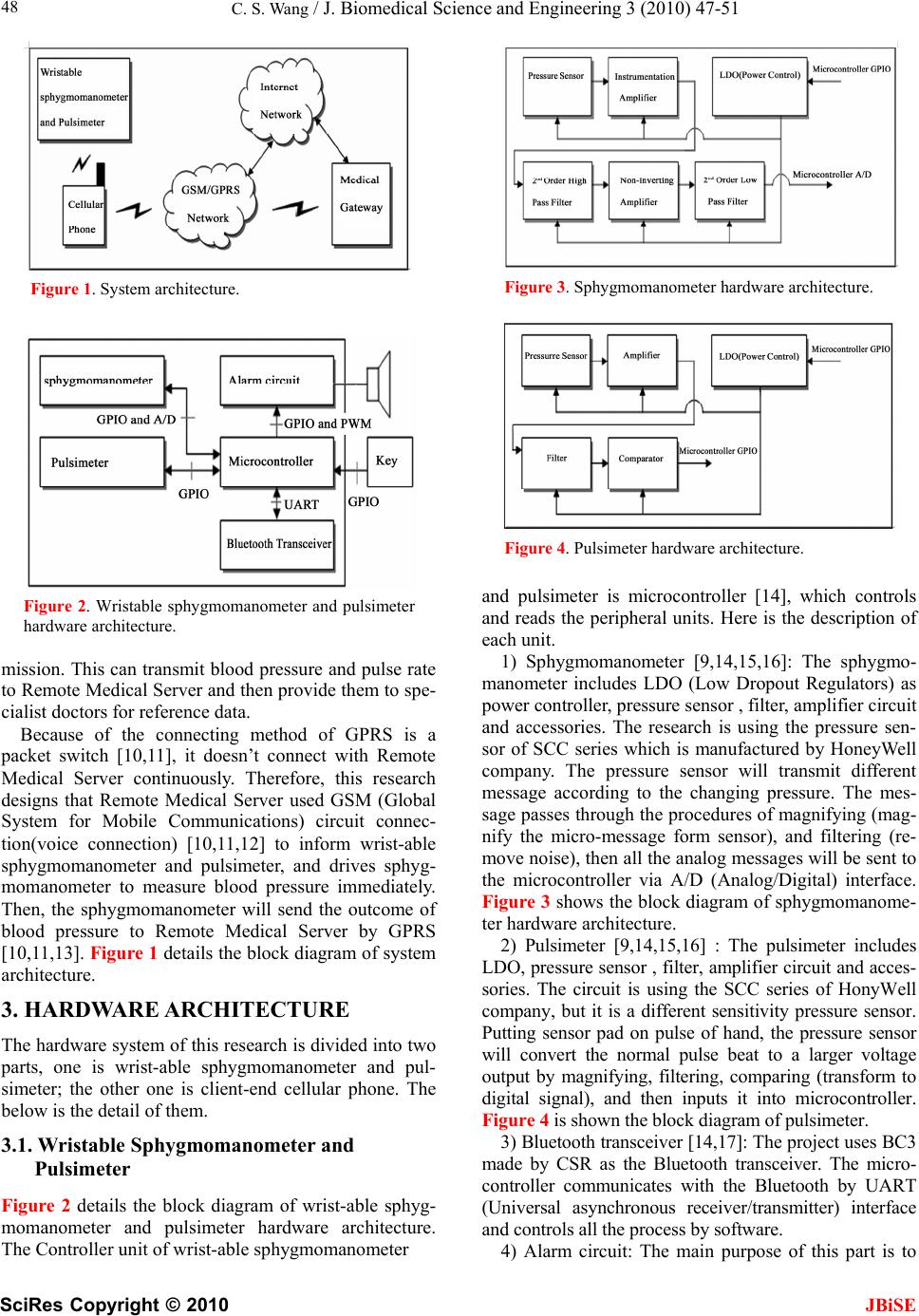
2. SYSTEM ARCHITECTURE
This research aims at designing wrist-able sphygmoma-
nometer and pulsimeter. We design a non-invasive
sphygmomanometer [9] to remind the user to measure
the blood pressure every hour. Pulsimeter is an elec-
tronic device which is based on pressure sensor, and can
observe pulse continuously. In order to avoid the influ-
ence of electromagnetic wave on the pacemaker, this
research is using the Bluetooth power class II equipment
to shorten the distance which wireless data transmission
device of sphygmomanometer transmits to client-end
cellular phone, then use the GPRS (General Packet Ra-
dio Service)[10,11] to do the long distance data trans-
C. S. Wang / J. Biomedical Science and Engineering 3 (2010) 47-51
SciRes Copyright © 2010 JBiSE
48
Figure 1. System architecture.
Figure 2. Wristable sphygmomanometer and pulsimeter
hardware architecture.
mission. This can transmit blood pressure and pulse rate
to Remote Medical Server and then provide them to spe-
cialist doctors for reference data.
Because of the connecting method of GPRS is a
packet switch [10,11], it doesn’t connect with Remote
Medical Server continuously. Therefore, this research
designs that Remote Medical Server used GSM (Global
System for Mobile Communications) circuit connec-
tion(voice connection) [10,11,12] to inform wrist-able
sphygmomanometer and pulsimeter, and drives sphyg-
momanometer to measure blood pressure immediately.
Then, the sphygmomanometer will send the outcome of
blood pressure to Remote Medical Server by GPRS
[10,11,13]. Figure 1 details the block diagram of system
architecture.
3. HARDWARE ARCHITECTURE
The hardware system of this research is divided into two
parts, one is wrist-able sphygmomanometer and pul-
simeter; the other one is client-end cellular phone. The
below is the detail of them.
3.1. Wristable Sphygmomanometer and
Pulsimeter
Figure 2 details the block diagram of wrist-able sphyg-
momanometer and pulsimeter hardware architecture.
The Controller unit of wrist-able sphygmomanometer
Figure 3. Sphygmomanometer hardware architecture.
Figure 4. Pulsimeter hardware architecture.
and pulsimeter is microcontroller [14], which controls
and reads the peripheral units. Here is the description of
each unit.
1) Sphygmomanometer [9,14,15,16]: The sphygmo-
manometer includes LDO (Low Dropout Regulators) as
power controller, pressure sensor , filter, amplifier circuit
and accessories. The research is using the pressure sen-
sor of SCC series which is manufactured by HoneyWell
company. The pressure sensor will transmit different
message according to the changing pressure. The mes-
sage passes through the procedures of magnifying (mag-
nify the micro-message form sensor), and filtering (re-
move noise), then all the analog messages will be sent to
the microcontroller via A/D (Analog/Digital) interface.
Figure 3 shows the block diagram of sphygmomanome-
ter hardware architecture.
2) Pulsimeter [9,14,15,16] : The pulsimeter includes
LDO, pressure sensor , filter, amplifier circuit and acces-
sories. The circuit is using the SCC series of HonyWell
company, but it is a different sensitivity pressure sensor.
Putting sensor pad on pulse of hand, the pressure sensor
will convert the normal pulse beat to a larger voltage
output by magnifying, filtering, comparing (transform to
digital signal), and then inputs it into microcontroller.
Figure 4 is shown the block diagram of pulsimeter.
3) Bluetooth transceiver [14,17]: The project uses BC3
made by CSR as the Bluetooth transceiver. The micro-
controller communicates with the Bluetooth by UART
(Universal asynchronous receiver/transmitter) interface
and controls all the process by software.
4) Alarm circuit: The main purpose of this part is to
C. S. Wang / J. Biomedical Science and Engineering 3 (2010) 47-51
SciRes Copyright © 2010 JBiSE
49
Figure 5. Client-end Cellular Phone Hardware Architecture.
Figure 6. The software algorithm of continuous
pulse and blood measuring and monitoring proce-
dure.
send a notice to the users, and then to perform blood
pressure measurement. Microcontroller can activate the
alarm circuit every hour. However, on the other one end,
Remote Medical Server can prescribe the blood pressure
measurement, so that the users can measure their blood
pressure when they require.
3.2. Client-End Cellular Phone Hardware
Architecture
Figure 5 details the block diagram of client-end cellular
phone hardware architecture, which includes two main
parts, Bluetooth and GSM/GPRS.
1) Bluetooth transceiver [14,17,18]: The hardware
framework is similar to the Bluetooth transceiver of
wrist-able sphygmomanometer and pulsimeter. It com-
municates with GSM/GPRS module by UART interface.
2) GSM Module [18]: It includes Baseband part and
RF part. The main components are Baseband IC (in-
cluding DSP), TFT-LCD, NOR Flash, SRAM, Power
Management IC and RF IC. We use MT6219 made by
MediaTek as the platform of the GSM/GPRS system.
4. SOFTWARE ALGORITHM
4.1. Continuous Pulse and Blood Measuring and
Monitoring Procedure
Pulse monitor procedure [14,15,16,19]: Microcontroller
Figure 7. The software algorithm of measure blood pre-
sure procedure.
reads the pulsimeter every minute, then transmits the
results to the client-end cellular phone by Bluetooth SPP
(Serial Port Profile).
Blood pressure measure procedures [9,14,15,16,19]:
Microcontroller enables alarm system to inform user
every hour that the time requires to measure the blood
pressure. Users need to put hand on the proper position
so that sphygmomanometer can have a better detection.
While the users put hand on proper position and push
trigger button, then the microcontroller controls pul-
simeter’s LDO to stop action and start to measure the
blood pressure. After that, microcontroller transmits
blood pressure to the cellular phone by Bluetooth SPP,
and to activate pulsimeter. If the user doesn’t do the ac-
tion of blood pressure measurement, the microcontroller
would re-activate pulsimeter after a while. The software
algorithm of continuous pulse and blood measurement
and the monitoring procedure is shown in Figure 6 and
Figure 7.
4.2. Client-End Clelular Phone Data Handling
Procedure
While the Bluetooth of mobile receives the data from the
Bluetooth of wrist-able sphygmomanometer and pul-
simeter, it analyzes the data of blood pressure or pulse
and to store (includes the measurement time) individu-
C. S. Wang / J. Biomedical Science and Engineering 3 (2010) 47-51
SciRes Copyright © 2010 JBiSE
50
Figure 8. The software algorithm of client-end cellular
phone data handling procedure.
Figure 9. The software algorithm of remote medical
server claim for mearuring blood pressure.
ally at first. Finally, it establishes GPRS connection. Af-
ter successful connecting, mobile scans stored blood
pressure and pulse data, and then it transmits to the Re-
mote Medical Server if the data has not been sent yet.
The software algorithm of mobile data handling proce-
dure is shown on Figure 8 [13,19,20,21].
4.3. Remote Medical Server Claim for Measur-
ing Blood Pressure
If the doctor considers that it is necessary to get the pa-
tient’s current blood pressure-immediately, he/she can
call to client-end cellular phone by GSM module on the
Remote Medical Server. While client-end cellular phone
receives incoming call form server-end, the Bluetooth
SPP transmits command of measuring blood pressure to
wrist-able sphygmomanometer and pulsimeter. While
wrist-able sphygmomanometer and pulsimeter receive
the command from the Remote Medical Server, they
activate blood pressure measurement and transmit pro-
cedures (Figure 6, 7, 8). The software algorithm of Re-
mote Medical Gateway claims for measuring blood
pressure is shown in Figure 9 [13,19,20,21].
5. CONCLUSIONS
It is a fatal risk for the patient with artificial pacemaker
implementation while the mobile connection is close to
the heart. The artificial pacemaker will consider the
electromagnetic wave from mobiles is heart signal, then
to do the wrong stimulation on muscle fiber of heart
ventricle. However, continuous pulse and blood pressure
observation is very essential for the patient of arrhythmia
with hypertension coronary arterial heart disease or heart
failure. Based on this following the Bluetooth power
class II RF test specification, we have designed a port-
able Bluetooth medium. We expect this system will be
benefit for the patients of arrhythmia with hypertension
coronary arterial heart disease or heart failure and never
cause any inconvenience to their daily life.
REFERENCES
[1] http://www.surgeryencyclopedia.com/La-Pa/Pacemakers.
html.
[2] Tacey, S. and Ronald, A. (1992) The effects of electro-
magnetic fields on cardiac pacerkers. IEEE Transactions
on Broadcasting, 38.
[3] Barbaro, V., Bartolini, P., Donato, A., et al. (1995) Do
European GSM mobile cellular phones pose a potential
risk to pacemaker patients? PACE, 18, 1218-24.
[4] Okan, E., MD, (2002) Electromagnetic interference on
pacemakers. Indian Pacing Electrophysiol J., 2(3), 74-78.
[5] Hayes, D.L., Wang, P.J., Reynolds, D.W., et al. (1997)
Interference with cardiac pacemakers by cellular tele-
phones. N. Eng. J. Med, 336, 1473-9.
[6] Bluetooth, (2004) Specification of the bluetooth system
core. Version 2.0.
[7] Bluetooth, (2004) Radio frequency test suite structure
(TSS) and test purposes (TP) specification 1.2, Revision
1.2.3.
[8] Nissila, S., Sorvisto, M., Sorvoja, H., Vieri-Gashi, E. and
Myllyla, R. (1998) Non-invasive blood pressure mea-
surement based on the electronic palpation method.
C. S. Wang / J. Biomedical Science and Engineering 3 (2010) 47-51
SciRes Copyright © 2010
51
JBiSE
Engineering in Medicine and Biology Society, Procee-
dings of the 20th Annual International Conference of the
IEEE, 4, 1723-1726.
[9] Lin, Y.B. and Imrich, C. (2000) Wireless and mobile
network architectures, Wiley Computer Publishing, 1
Edition (October 2).
[10] Michel, M., Marie-Bernadette, P. (1992) The GSM Sys-
tem for Mobile Communications, Telecom Publishing.
[11] Wang, C.S., Lee, J.H. and Chu Y.T. (2007) Mobile tele-
medicine application and technologies on GSM, bioin-
formatics and biomedical engineering, ICBBE, The 1st
International Conference on 6-8 July 2007, 1125-1128.
[12] (2004)MediaTek, AT command set, Revision: 0.03.
[13] (2005) National Semiconductor, SC14440/431/432,
SC14435, SC14436/437/438. Baseband processor for
PP/FP DECT and WDCT, V1.1, June 16.
[14] (2004) Champion, CM2838, 300mA Low Esr CMOS
LDO with Enable, Rev. 1.1.
[15] (2002) HoneyWell, SSC series pressure sensors 0-5 psi
through 0-300 psi.
[16] CSR, (2006) BlueCore3-ROM CSP Product Data Book.
[17] MediaTek, (2004) MT6219 GSM/GPRS Baseband Pro-
cessor Data Sheet, Revision 1.00.
[18] Bluetooth SIG, (2001) Specification of the Bluetooth
System Profile, Part K: 5 Serial Port Profile, Version 1.1.
[19] (2003) MediaTek, Customer Device Driver Document,
Revision 0.1.
[20] PixTel, (2004) Writing Applications Using PixTel MMI
Platform, Version 1.3.