Journal of Electromagnetic Analysis and Applications
Vol. 3 No. 6 (2011) , Article ID: 5657 , 6 pages DOI:10.4236/jemaa.2011.36039
History and Advancement of the Family of Log Periodic Toothed Planer Microstrip Antenna
![]()
Faculty of Engineering and Technology, Manav Rachna International University, Faridabad, India.
Email: vaisharti@gmail.com
Received April 8th, 2011; revised May 10th, 2011; accepted May 19th, 2011.
Keywords: Log Periodic Antenna, Probe Feed, Wide Band Antenna, Improved Bandwidth
ABSTRACT
This paper presents the family of logarithmically periodic toothed planer antennas. In this the dimensions of the successive sections were increased in geometric progression for a wide bandwidth usage. A band width of 7% for trapezoid toothed, 26% for zigzag toothed and 50% for cross-toothed VSWR < 2 has been obtained from the proposed antennas. Investigations on the gain and radiation characteristics have been carried out. The investigations show that the proposed designs not only offers the enhanced bandwidth but also possesses the same characteristics over the desired frequency band at same probe feed position.
1. Introduction
Researches on new types of broadband logarithmically periodic antennas structures are studied. The Log-Periodic Antenna (LPA) is investigated as a new type of antenna, whose properties vary periodically with the logarithm of frequency, and provides wide bandwidth, broad beam width, and high gain. This antenna has smaller transverse dimensions than another antenna types. The antennas have pattern and impedance characteristics which are essentially independent of frequency over theoretically unlimited bandwidths. Data transmission at higher rates requires wider bandwidths for the elements constituting a communication link. This required wideband antennas be designed and used [1,2]. In logarithmically periodic antenna [3], the electrical properties vary with log of operation frequency. The high frequency antenna described by Duhamel and Berry [5,6] was periodic structure in which the dimension of successive sections was increased in geometric progression. The log periodic toothed trapezoidal antenna (LPTTA) can be slightly modified to obtain a refined geometry referred to log periodic zigzag and cross toothed antennas. The different (log periodic toothed antennas) are also specified by angle in a manner similar to the LPTTA described earlier [7-10]. The important feature of these antennas is that they represent an earlier link to the development of log-periodic dipole antenna. The initial design based on the concept of log periodic structure was the log periodic toothed planar antenna following the angle concept, if one tooth has width , the next smaller one is
  wide, third is
  and so on. Let the width of the widest be sigma1, which is approximately one quarter wavelength corresponding to the lower frequency limit. Then the widest of nth tooth, sigma n
 (1)
(1)
where  is a constant representing the geometric ratio of width (n + 1). The tooth’s to width of nth tooth. Taking log on both sides
 (2)
(2)
For a given antenna log and log
 are constant.
Consequently the log of  increases in equal steps with n. That is,
  increases periodically, hence the name log periodic. It is also implied that whatever the electrical properties the antenna may have at a frequency
 , will be repeated at frequency given by
 (3)
(3)
2. Antenna Design
The proposed configuration of antennas along with the same position of the probe feed at origin (0, 0) is shown in Figures 1, 2 and 3. The design of log periodic toothed antennas [11-17] depends upon various parameters such as geometric ratio (τ), tooth width (σ) and angles α, β (alpha, beta). Here we have taken the highest frequency
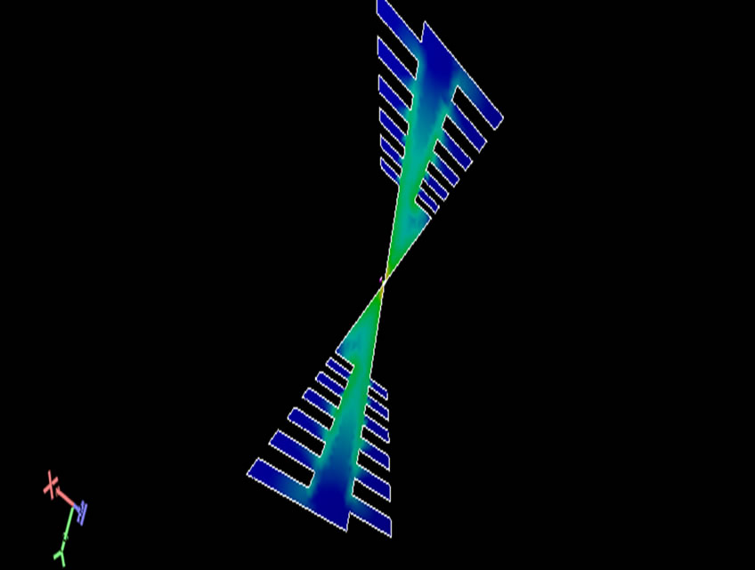
Figure 1. The proposed configuration of trapezoidal toothed antenna.
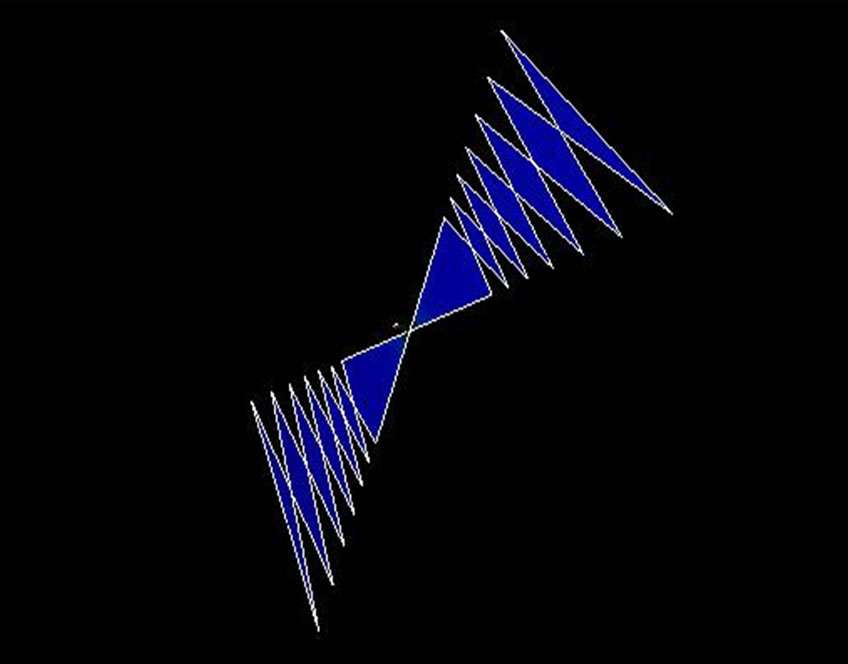
Figure 2. The proposed configuration of cross toothed antenna.
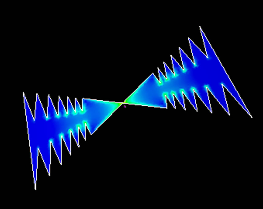
Figure 3. The proposed configuration of zigzag toothed antenna.
18 GHz. We have taken frequency range 2 GHz to 18 GHz.
Design for 7 Cells of the Antenna
If we take the 1st cell to be equal to λ/2 then
R6 = 9.8 mm r5 = 10.621 mm
R5 = 11.52 mm r4 = 12.50 mm
R4 = 13.56 mm r3 = 14.705 mm
R3 = 15.95 mm r2 = 17.30 mm
R2 = 18.77 mm r1 = 20.35 mm
R1 = 22.08 mm
Taking τ = 0.85 with α = 60 and β = 20
Dielectric constant (ε) = 4.4
Loss tangent = 0.0002
Z-top = 1.6
3. Result and Discussion
The proposed antenna has been analyzed using IE3D Software using probe feed at (0, 0) [20]. Figures 4, 5 and 6 shows the variations of VSWR with frequency for LPTA for trapezoidal, cross and zigzag geometry. For trapezoidal toothed antenna as we can see from Figure 4 that for frequency 13.0295 GHz to 13.9 GHz the input VSWR is lesser than two (VSWR < 2). This is the usable range of the antenna, i.e. 7% of bandwidth is available. For cross toothed antenna as observed from Figure 5 that for frequency 11.025 GHz to 13.9 GHz the input VSWR is lesser than two (VSWR < 2). This is usable range of the antenna, i.e. 26% of bandwidth is available and for zigzag toothed antenna as observed from Figure 6 that for frequency 10.5 GHz to 16.3 GHz the input VSWR is lesser than two (VSWR < 2). This is the most useful range of the antenna, i.e. 50% of bandwidth is available. With the analysis of the antenna bandwidth it is observed that bandwidth is improved for the geometry of Figures 2 and 3 as compare to Figure 1. Similarly from the gain versus frequency plot in Figures 7, 8 and 9 of the trape-
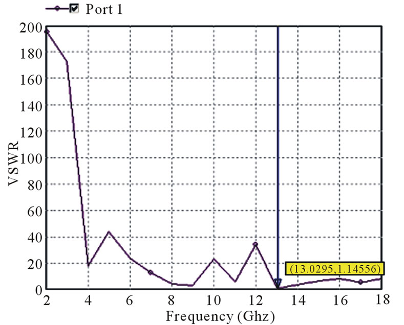
Figure 4. Plot of VSWR versus frequency of trapezoidal antenna.
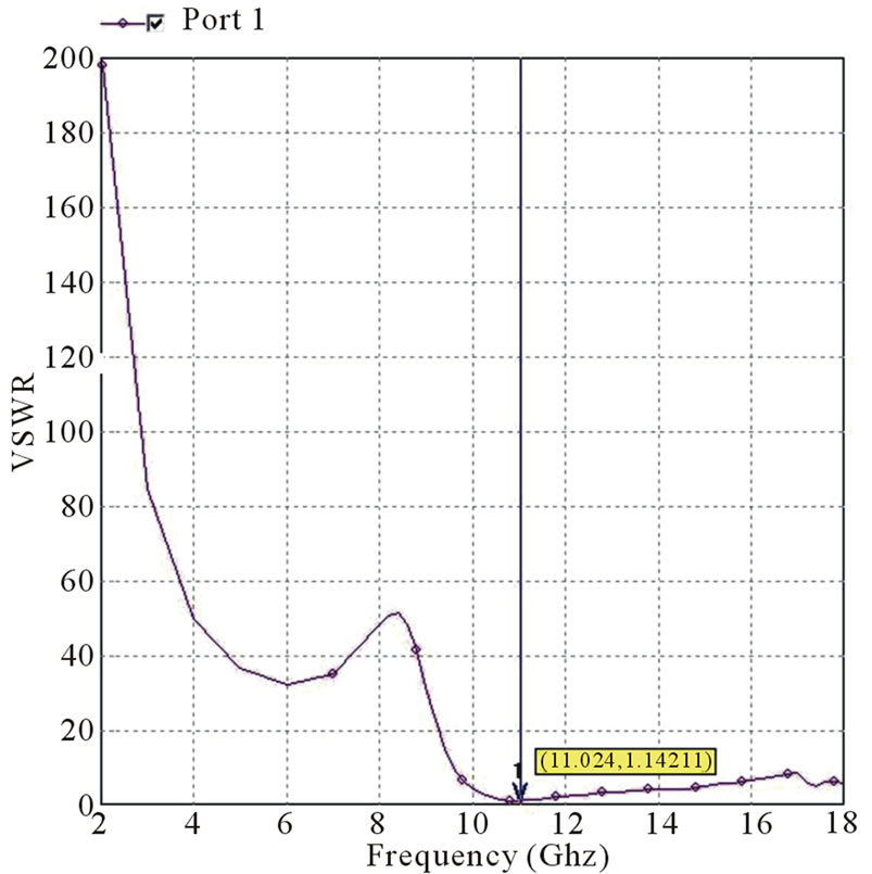
Figure 5. Plot of VSWR versus frequency of cross antenna.
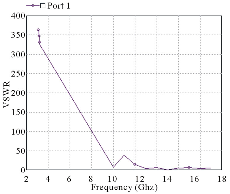
Figure 6. Plot of VSWR versus frequency of cross antenna.
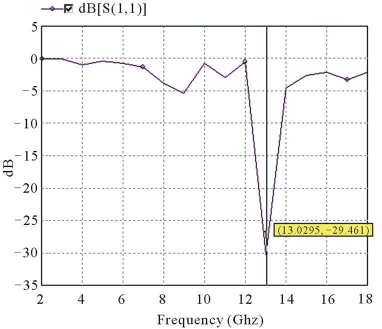
Figure 7. Plot of gain versus frequency.
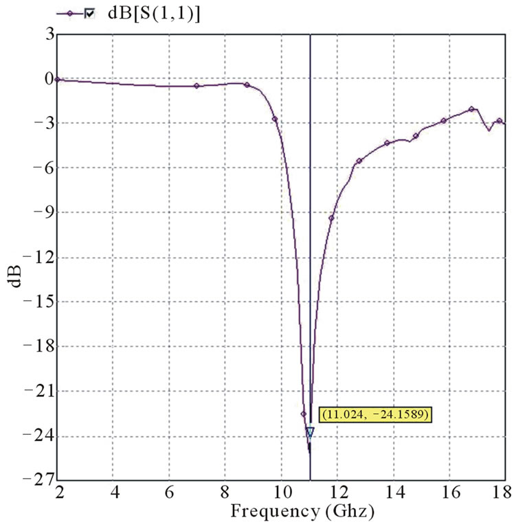
Figure 8. Plot of gain versus frequency for cross toothed antenna.
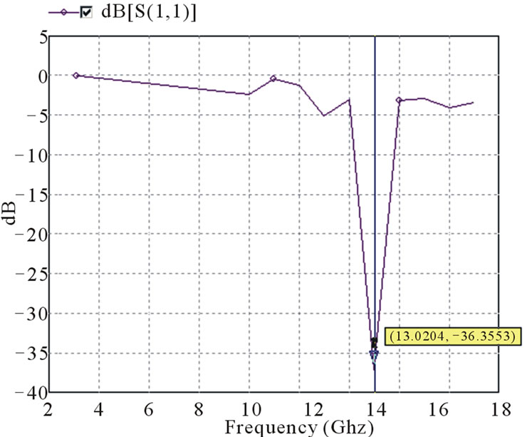
Figure 9. Plot of gain versus frequency for zigzag toothed antenna.
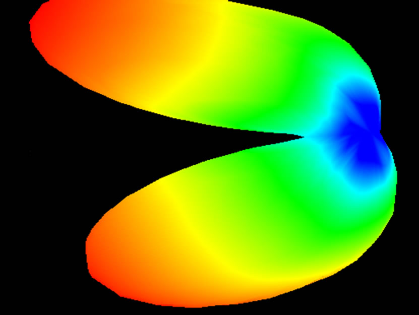
Figure 10. 3D Radiation pattern of trapezoid toothed antenna.
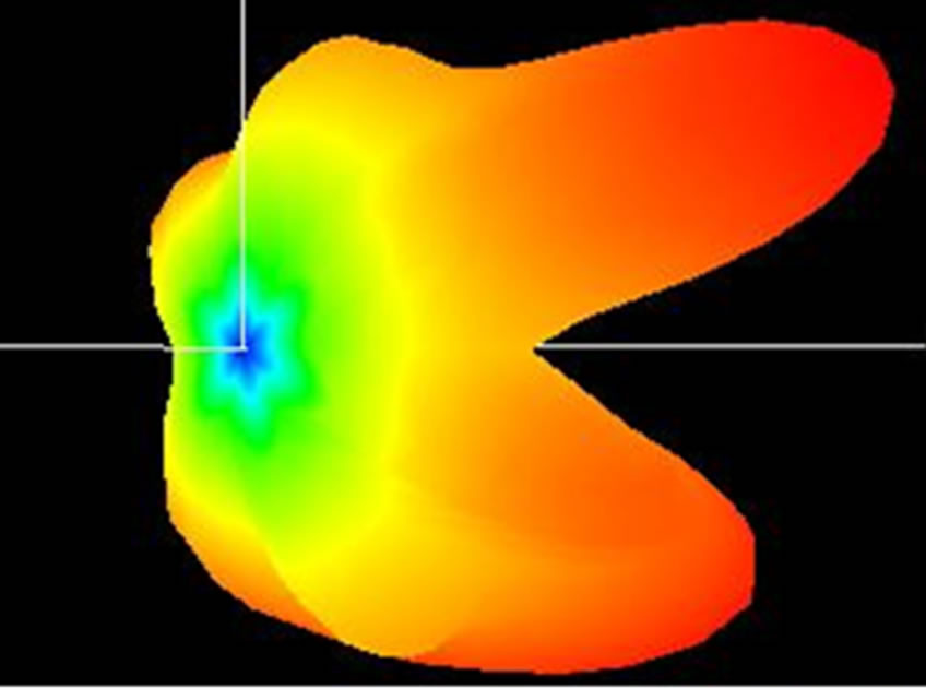
Figure 11. 3D Radiation pattern of cross toothed antenna.
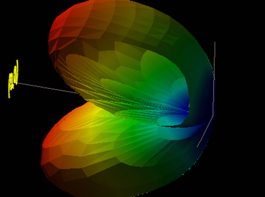
Figure 12. 3D Radiation pattern of zigzag toothed antenna.
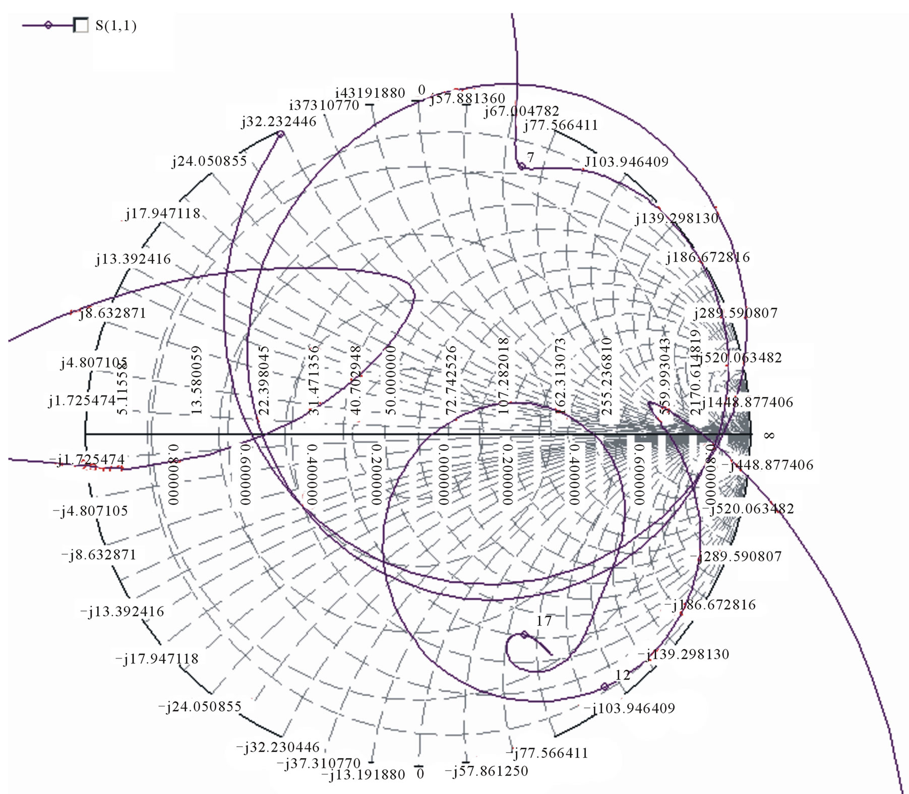
Figure 13. Smith Chart of trapezoidal toothed antenna.

Figure 14. Smith Chart of cross toothed antenna.
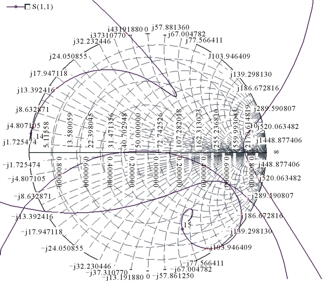
Figure 15. Smith Chart of zigzag toothed antenna.
zoidal, cross and zigzag pattern it is observed that the maximum gain is obtained for the zigzag geometry so we can practically implement the zigzag pattern and optimize it for the better results for a wide band usage. The 3D Radiation pattern and smith chart of the proposed trapezoid, cross and zigzag antenna are shown in Figures 10, 11, 12,13, 14 and 15.
4. Conclusions
A log periodic self complementary toothed planer probe feed antennas have been proposed. Log periodic zigzag toothed antenna and Log periodic crossed toothed antenna have better results as compare to the basic geometry as shown in Figure 1. The proposed designs have enhanced bandwidth, gain, radiation pattern and VSWR and similar characteristics throughout the operating bandwidth.
5. Acknowledgements
The author thankfully acknowledges the authorities of Manav Rachna International University, Faridabad, Haryana, for the provision of facility for this research work.
REFERENCES
- C. A. Balani, “Antenna Theory,” Antenna Theory, Wiley, New York, 2007.
- R. C. A. DuHamel, H. Balani and D. E. Isbell, “Broadband Loga Rithmically Periodic Antenna Structures,” IRE National Convention Record, May 1957, pp. 119-128.
- C. A. Balani, “Antenna Theory: Analysis and Design,” 2nd Edition, John Wiley and Sons, New York, 1997.
- C. E. Smith, “Log Periodic Antenna Design Handbook,” 1st Edition, Ohio, 1966.
- R. H. DuHamel and E. G. Berry, “Logarithmically Periodic Antenna Arrays,” IRE Wescon Convention Record, August 1958, pp.161-177. doi:10.1109/WESCON.1958.1150224
- R. H. DuHamel and F. R. Ore, “Logarithmically Periodic Antenna Design,” IRE National Convention Record, 1958, pp. 139-152.
- V. H. Rumsey, “Frequency Independent Antennas,” IRE National Convention Record, March 1957, pp. 114-118. doi:10.1109/IRECON.1957.1150565
- R. L. Carrel, “The Design of Log-Periodic Dipole Antennas,” IRE National Convention Record, March 1961, pp. 61-75. doi:10.1109/IRECON.1961.1151016
- W. L. Stutzman and G. A. Thiele, “Antenna Theory and Design,” 2nd Edition, John Wiley and Sons, New York, 1998.
- V. H. Rumsey, “Frequency Independent Antennas,” Academic Press, New York, 1996.
- R. S. Elliott, “A View of Frequency Independent Antennas,” The Microwave Journal, Vol. 5, December 1962, pp. 61-68.
- Y. Mushiake, “Self-Complementary Antennas,” SpringerVerlag, Berlin, 1996.
- R. L. Carrel, “The Design of Log-Periodic Dipole Antennas,” IRE National Convention Record, 1961, pp. 61-75.
- W. L. Stutzman and G. A. Thiele, “Antenna Theory and Design,” 2nd Edition, John Wiley and Sons, New York, 1998.
- D. F. Di Fonzo, “Reduced Size Log Periodic Antennas,” The Microwave Journal, Vol. 7, December 1964, pp. 37-42.
- M. D. Singh, S. P. Kosta and A. Singh, “Log Periodic Antenna with Loop Elements,” International Journal of Electronics, Vol. 32, No. 1, 1972, pp. 81-84. doi:10.1080/00207217208938272
- D. Sharma and R. Kumar, “Design and Analysis of Five Element Microstrip Log-Periodic Antenna,” International Conference on Applications of Electromagnetism and Student Innovation Competition Awards, Taipei, 11-13 August 2010, pp. 210-214.
- D. Varon and R. B. Kieburtz, “Theoretical Analysis of a Log Periodic Structure”, Antennas and Propagation Society International Symposium, 21-24 September 1964, pp. 58-61. doi:10.1109/APS.1964.1150143.
- O. Ergui and L. Gruel, “Circular Arrays of Log Periodic Antennas for Broadband Applications,” Proceedings of the European Conference on Antennas and Propagation, Nice, 6-10 November 2006, p. 503.
- IE3D Software Release 8 Developed by m/s Zealand software Inc.