Journal of Electromagnetic Analysis and Applications
Vol. 1 No. 4 (2009) , Article ID: 1121 , 6 pages DOI:10.4236/jemaa.2009.14040
Numerical Computation of Resonant Frequency of Shorting Post Loaded Gap-Coupled Circular Microstrip Patch Antennas
1Department of Electronics and communication Engineering, Jaypee University of Information Technology, Solan, India; 2Embedded Systems Innovation Laboratory, Tata Consultancy Services, Bangalore, India
Email: erpradeep_tiet@yahoo.co.in
Received April 17th, 2009; revised May 30th, 2009; accepted June 5th, 2009.
Keywords: Gap-Coupling, Microstrip Antennas, Shorting Post, Resonant Frequency
ABSTRACT
In this paper, the numerical computation of resonant frequency of the two gap-coupled circular microstrip patch antenna loaded with shorting post by using cavity model is presented. The numerically computed results are compared with simulated results. The two gap-coupled circular microstrip patch antenna loaded with shorting post miniaturize the cross-sectional dimension of the radiating patch at the microwave frequency, which is useful for short range communications or contactless identification systems. The simulation has been performed using method-of-moments based commercially available simulator IE3D.
1. Introduction
An explosive growth of the wireless radio frequency identification market such as electronic toll collection and more generally wireless road-to-vehicle communication systems is currently observed in the microwave band. In the short range communications or contactless identification systems, antennas are key components, which must be small, low profile, and with minimal processing costs [1,2]. The microstrip patch antennas are of great interest for aforementioned mentioned applications due to their thin and compact structures. The flexibility afforded by microstrip antenna technology has led to a wide variety of design and techniques. The main limitations of the microstrip antennas are low efficiency and narrow impedance bandwidth. The bandwidth of the microstrip antenna can be increased using various techniques such as by loading a patch, by using a thicker substrate, by reducing the dielectric constant, by using gap-coupled multi-resonator etc [3–5]. However, using a thicker substrate causes generation of spurious radiation and there are some practical problems in decreasing the dielectric constant. The spurious radiation degrades the antenna parameters. Among various antenna bandwidth enhancement configurations, the two gap-coupled circular microstrip patch antenna is most elegant one. So, gap-coupling is the suitable method for enhancing the impedance bandwidth of the antennas [6,7]. In the cofigration of gap-coupled microstrip antennas method, two patches are placed close to each other. The gap-coupled microstrip antennas generate two resonant frequencies and the bandwidth of the microstrip antennas can be increased [6].
There exist a wide range of basic microstrip antenna shapes such as rectangular, circular and triangular patch shapes which are commonly used patches. For these patches, operating at their fundamental mode resonant frequency, are of the dimension of the patch is about half wavelength in dielectric. At lower frequencies the size of the microstrip antennas becomes large. In modern communication systems the compact microstrip patch antennas are desirable. The size of the microstrip antenna can be reduced by shorting the patch. Changing the basic patch shape can give rise to substantial size reduction. Further decrease in size can be obtained by loading the basic shapes by shorting post or slots [8–10].
In [11,12], circular microstrip patch antenna with dual frequency operation is designed by shorting the patch and the results are compared with the conventional circular microstrip antenna (without a shorting post) which shows that the size of the circular microstrip antenna can be reduced for the same frequency application. It is also observed that the resonant frequency of the circular microstrip antenna with shorting post can be varied by varying its location. In [13,14], it is shown that the loaded circular microstrip antenna has two modes that is TM01 and TM11. Recently, we have also designed two gap-coupled circular microstrip patch antenna without shorting post which generates two modes that is TM11 and TM21 mode [15].
In the present paper, the two gap-coupled circular microstrip patch antenna is loaded with a shorting post to minimize the size of the antenna structure and it is seen that it generates the three modes that is TM01, TM11 and TM21. The resonant frequency of TM01 mode of the proposed antenna is lower as compared to TM11 and TM21 mode of the two gap-coupled circular microstrip antennas as reported in [15]. The numerical computation of the resonant frequency of the shorting post loaded two gapcoupled circular microstrip antenna is performed and the results are compared with the simulated results. The simulation is performed by using the IE3D simulator which is based on the method-of-moment. This paper is structured as follows. In Section 2, the geometrical configuration of the two gap-coupled circular microstrip patch antenna is discussed. In Section 3, the proposed antenna is analyzed theoretically. The Section 4 discusses the analytical and simulated results of the proposed antenna. Finally, Section 5 concludes the work.
2. Antenna Configuration
The geometrical configuration of two gap-coupled circular microstrip patch antennas loaded with shorting post is shown in Figure 1. The patch of radius  mm is the feed patch and other patch of radius
  mm is the parasitic patch. The parasitic patch is excited by the gap-coupling whereas the feed patch is excited by the probe feeding technique. The parasitic patch introduces another resonance near the main resonance and proper adjustment of the structure parameters, bandwidth can be enhanced. The feed patch is shorted by shorting post of diameter
 . The height and permittivity of the substrate is
  mm and
 , respectively. The gap distance between the adjacent edges of the feed patch and parasitic patch is
 .
.
3. Theory
Now we divide the structure in two concentric regions; region I and region II as shown in Figure.2.The inner radii of region I is  and outer radii of region I is ‘a’. The inner radius of region II is ‘b’ and outer radius of region II is ‘c’.
Now, we consider the field expressions for given TMnp mode in these two regions [16].
In region I ( ):
):
The solution of the wave equation in cylindrical coordinates for region I gives the field expressions as:
 (1)
(1)
 (2)
(2)
The expression for  is omitted for brevity. The
  and
and  are the axial electric field and azimuthal magnetic field, respectively for region I,
  and
and  are the angular frequency and propagation constant for TMnp mode, respectively.
  is the Bessel function of first kind of order
  and
and  is the Bessel func-

Figure 1. Geometrical configuration of the two gap-coupled circular microstrip patch antenna loaded with shorting post
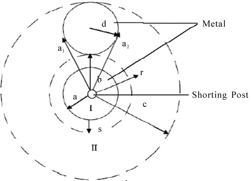
Figure 2. Analytical configuration of the two gap-coupled circular microstrip patch antenna loaded with shorting post
tion of second kind of order . C1 and C2 are the amplitude constants for region I.
In region II ( ):
):
The solution of the wave equation in cylindrical coordinates for region II gives the field expressions as:
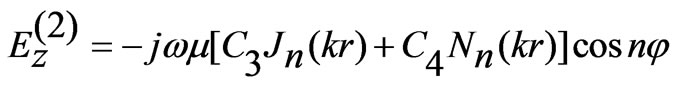 (3)
(3)
 (4)
(4)
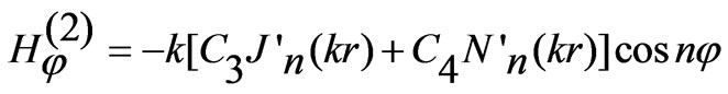
where C3 and C4 are the amplitude constants for region II. Considering the parasitic patch in isolation the boundary condition of vanishing  can be applied as:
 for
for  and
and 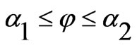 (5)
(5)
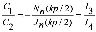
Thus,
 (6)
(6)
Therefore the field expression in region II can be rewritten as:
 (7)
(7)
 (8)
(8)
where  is a constant dependant on given mode n and
 (9)
(9)
Similarly,
 for
for 
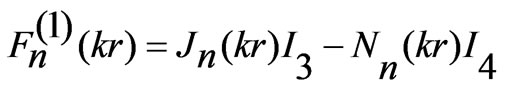
Thus the field expression in region I is:
 (10)
(10)
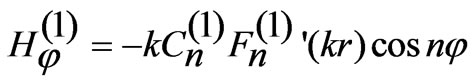 (11)
(11)
where  is a constant and
 (12)
(12)
We now consider the gap between two regions at the point of coupling between two patches as a  -type network [15] as shown in Figure 3.
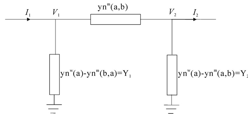
Figure 3. An equivalent circuit diagram of the two gap-gap coupled circular microstrip patch antenna
In Figure 3,  are the wall admittances of individual patches and
  is the mutual admittance between the two patches.
Here,

where  denotes magnetic coupling and is given by

where  is the substrate height and
  is a correction factor. The formula for magnetic coupling is derived for infinitely thin cylindrical lines. However, to take account for substantial area of each cylinder an empirical correction factor is utilized. From the condition of discontinuity of current in these two regions, we can write:
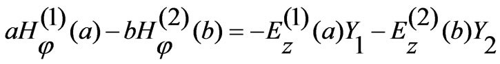 (13)
(13)
using this expression, we obtain:
 (14)
(14)
For small gap normal component of electric field is continuous at  where
where .
.
Therefore  at
at .
.
From this
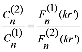 (15)
(15)
Equating Expressions (14) and (15) we get:
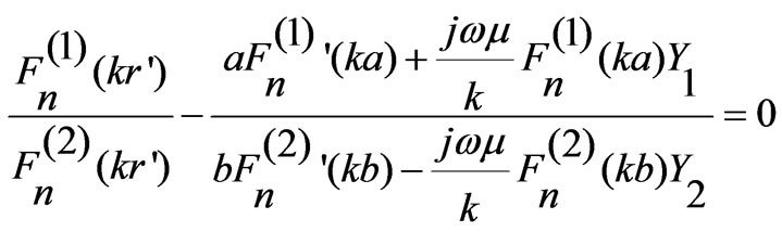 (16)
(16)
The above transcendental equation gives the resonant frequency of a given TMnp mode.
4. Results and Discussion
The proposed simulation model of two gap-coupled circular microstrip patch antenna is as shown in Figure 1. It is clearly seen that, for the short-circuited patch antenna, the input impedance become very sensitive to the feed position and strongly depends on the distance between the shorting post and the feed position [2–10]. The determination of all relevant parameters for the shorting post microstrip patch antenna is straight forward once the resonant frequency has been determined. It has been shown that the resonant frequency depends critically on dimension of the shorting post and gap distance between adjacent edges of the feed patch and parasitic patch.
In Figure 4, the variation of resonant frequency of different modes with radius of shorting post in feed patch is shown. It is important to note that at a fixed frequency, the patch size can be increased or decreased, depending on the radius of the shorting post. As the radius of the shorting post increases the resonance frequency of the proposed antenna is increases for TM01 TM11 and TM21 modes as shown in Figure 4 In Figure 5, the variation of resonant frequency of different modes with gap distance between adjacent edges of the feed patch and parasitic patch is shown. The resonant frequency decreases with increasing the gap distance between adjacent edges of the feed patch and parasitic patch for TM01 TM11 and TM21 modes as shown in Figure 5. The proposed antenna is also simulated using IE3D simulator. The numerically computed and simulated results are compared which shows good agreement as shown in Figure 4 and Figure 5.
The diameter of the shorting post and the gap distance between the adjacent edges of feed patch and parasitic patch also play an important role in the overall size of the patch conductor. Basically, the shorting post is modeled as an inductance parallel to the resonant LC circuit describing a reference resonant mode of the unloaded (without shorting post) patch. In an equivalent circuit, new resonance mode (with shorting post) can be viewed as resulting from the inductance due to shorting post. Using the resonant frequency of TM01 mode, the size of the gap-coupled circular microstrip antenna can be reduced for same frequency applications, because the resonant frequency of this mode is much less than the resonant frequencies of the conventional gap-coupled circular microstrip antenna presented in [15]. By varying the various parameters such as diameter of shorting post and the gap distance between adjacent edges, the reso-
 (a)
(a)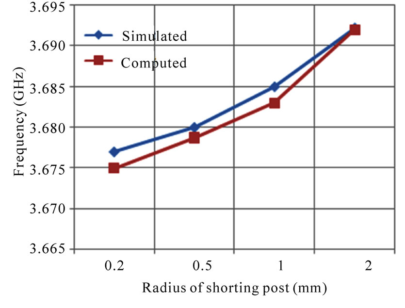 (b)
(b) (c)
(c)
Figure 4. Variation of the resonant frequency with radius of the shorting post of the proposed antenna for, (a) TM01 mode with s = 0.5 mm; (b) TM11 mode with s = 0.5 mm and (c) TM21 mode with s = 0.5 mm
nant frequencies of the presented antenna can be controlled.
To validate the presentation of mode numbers the simulated current density on the patches are presented in Figure 6, 7 and 8. It is seen that the mode numbers are
 (a)
(a)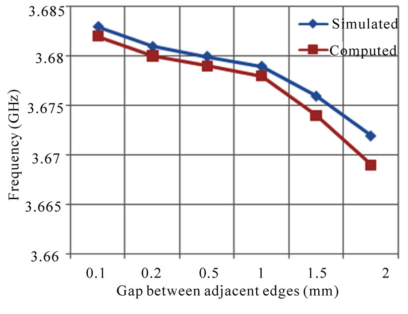 (b)
(b) (c)
(c)
Figure 5. Variation of the resonant frequency with gap distance between adjacent edges of the feed patch and parasitic patch for (a) TM01 mode with radius of shorting post = 0.5 mm, (b) TM11 mode with radius of shorting post = 0.5 mm, and (c) TM21 mode with radius of shorting post = 0.5 mm
predicted accurately. In this case, the current density towards ‘Red’ colour is maximum and current density towards ‘Blue’ colour is minimum. The current density represented by ‘Yellow’ colour is between the ‘Red’ and ‘Blue’. The left hand side patch is the feed patch and the right side patch is parasitic patch. In Figure 6, the yellow region is at the center of the feed patch and blue region at the surroundings of the green region conveys the TM01 mode. In Figure 7, it is seen that on the feed patch a yellow region and a blue region exists. This accounts for TM11 mode. Two blue regions in Figure 8 convey the existence of TM21 mode.
5. Conclusions
In this paper, a numerical model for shorting post loaded two gap-coupled circular microstrip patch antenna is developed. The comparison between the numerically computed and simulated results shows good agreement in resonant frequency for TM01, TM11, and TM21 modes. The proposed gap-coupled microstrip antennas loaded
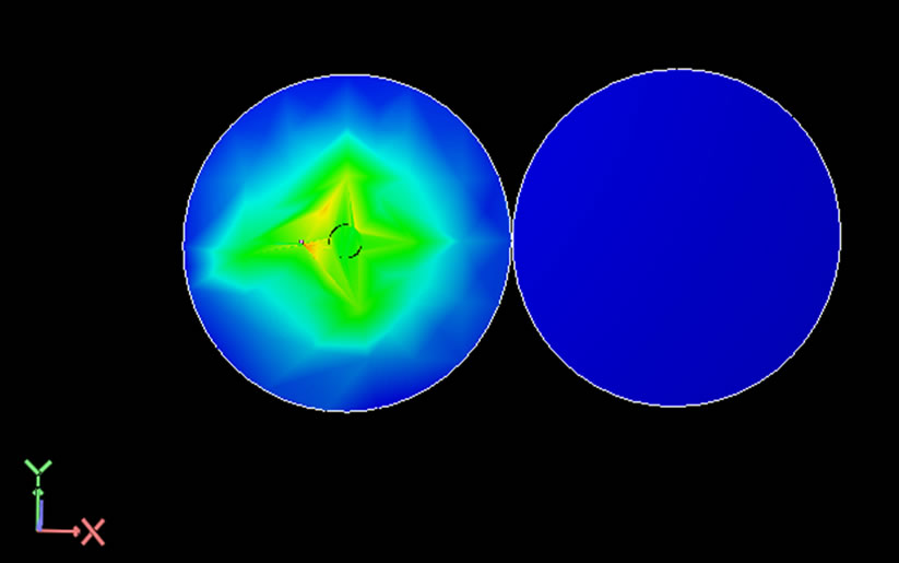
Figure 6. The current density distribution on the proposed two gap-coupled circular microstrip patch antennas loaded with shorting post for TM01 mode at frequency 2.149 GHz for gap distance between adjacent edges of feed patch and parasitic patch 0.1 mm and radius of shorting post 1.5 mm

Figure 7. The current density distribution on the proposed two gap-coupled circular microstrip patch antennas loaded with shorting post for TM11 mode at frequency 3.6912 GHz for gap distance between adjacent edges of feed patch and parasitic patch 0.1 mm and radius of shorting post 1.5 mm

Figure 8. The current density distribution on the proposed two gap-coupled circular microstrip patch antennas loaded with shorting post for TM21 mode at frequency 3.8474 GHz for gap distance between adjacent edges of feed patch and parasitic patch 0.1 mm and radius of shorting post 1.5 mm
with shorting post can be used for multi frequency applications. Also the size of the proposed antenna can be controlled by varying either gap distance between adjacent edges of the feed patch and parasitic patch or radius of the shorting post. The proposed model can be extended to multiple resonators as well as analysis with different patch sizes.
6. Acknowledgement
Authors are sincerely thankful to the reviewers for critical comments and suggestions to improve the quality of the manuscript.
REFERENCES
- M. Hirvonen, P. Pursula, K. Jaakkola, and K. Laukkanen, “Planer inverted F antenna for radio frequency identification,” Electronics Letter, Vol. 40, No. 14, pp. 848–850, July 2004.
- A Sharma and G. Singh, “Design of single pin shorted three-dielectric-layered substrates rectangular patch microstrip antenna for communication systems,” Progress In Electromagnetic Research Letters, Vol. 2, pp. 157–165, 2008.
- R. Garg, P. Bhartia, I. Bahl, and A. Ittipiboon, “Microstrip Antenna Design Handbook,” Artech House: London, 2001.
- T. Chakravarty, S. Biswas, A. Majumdar, and A. De, “Computation of resonant frequency of annularing-loaded circular patch”, Microwave and Optical Technology Letter, Vol. 48, No. 3, pp. 622–626, 2006.
- D. M. Pozar, “Microstrip antennas,” Proceedings of the IEEE, Vol. 80, No. 1, pp. 79–91, January 1992.
- P Kumar, G. Singh, and S. Bhooshan, “Gap-coupled microstrip antennas,” Proceedings of the International Conference on Computational Intelligence and Multimedia Application, India, pp. 434–437, 2007.
- K. P Ray, S. Ghosh, and K. Nirmala, “Compact broadband gap-coupled microstrip antennas,” Proceedings of International Symposium on IEEE Antennas and Propagation Society, pp. 3719–3722, July 2006.
- R. B. Waterhouse, S. D. Targonski, and D. M. Kokoto, “Design and performance of small printed antennas,” IEEE Transactions on Antennas Propagation, Vol. 46, pp. 1629–1633, 1998.
- T. K. Lo, C.-O. Ho, Y. Hwang, E. K. W. Lam, and B. Lee, “Miniature aperture-coupled microstrip antenna of very high permittivity,” Electronics Letter, Vol. 33, pp. 9–10, January 1997.
- R. Porath, “Theory of miniaturized shorting post microstrip antennas,” IEEE Trans. Antennas Propagation, Vol. 48, No. 1, pp. 41–47, January 2000.
- C.-L. Tang, H.-T. Chen, and K.-L. Wong, “Small circular microstrip antenna with dual frequency operation,” Electronics Letter, Vol. 33, No. 73, pp. 1112–1113, 1997.
- K.-L. Wong and W.-S. Chen, “Compact microstrip antenna with dual-frequency operation,” Electronics Letter, Vol. 33, No. 8, pp. 646–647, April 1997.
- T. Chakravarty and A. De, “Investigation of modes tunable circular patch radiator with arbitrarily located shorting posts,” IETE Technical Review, Vol. 16, No. 1, pp. 109–111, January 1999.
- T. Chakravarty and A. De, “Design of tunable modes and dual-band circular patch antenna using shorting posts,” IEE Proceeding Microwaves, Antennas Propagation, Vol. 146, No. 3, pp. 224–228, 1999.
- P. Kumar, T. Chakravarty, G. Singh, S. Bhooshan, and S. K. Khah “Numerical computation of resonant frequency of gap coupled circular microstrip antennas,” Journal of Electromagnetic Waves and Applications, Vol. 21, No. 10, pp. 1303–1311, 2007.
- T. Chakravarty, S. M. Roy, S. K. Sanyal, and A. De, “A novel microstrip patch antenna with large impedance bandwidth. In VHF/UHF range,” Progress in Electromagnetics Research, Vol. 54, pp. 83–93, 2005.