Journal of Software Engineering and Applications
Vol.7 No.5(2014), Article ID:46096,12 pages DOI:10.4236/jsea.2014.75041
Challenges for Software Engineering in Automation
Birgit Vogel-Heuser1, Christian Diedrich2, Alexander Fay3, Sabine Jeschke4, Stefan Kowalewski5, Martin Wollschlaeger6, Peter Göhner7
1Institute of Automation and Information Systems, Technische Universität München, München, Germany
2Institute for Automation and Communication, Otto von Guericke University Magdeburg, Magdeburg, Germany
3Institute of Automation Technology, Helmut-Schmidt-University, Hamburg, Germany
4Institute of Information Management in Mechanical Engineering, RWTH Aachen University, Aachen, Germany
5Computer Science 11—Embedded Software Laboratory, RWTH Aachen University, Aachen, Germany
6Institute for Applied Computer Science, Dresden University of Technology, Dresden, Germany
7Institute of Industrial Automation and Software Engineering, University of Stuttgart, Stuttgart, Germany
Email: vogel-heuser@ais.mw.tum.de, christian.diedrich@ifak.eu, alexander.fay@hsu-hh.de, sabina.jeschke@ima-zlw-ifu.rwth-aachen.de, kowalewski@embedded.rwth-aachen.de, martin.wollschlaeger@tu-dresden.de, peter.goehner@ias.uni-stuttgart.de
Copyright © 2014 by authors and Scientific Research Publishing Inc.
This work is licensed under the Creative Commons Attribution International License (CC BY).
http://creativecommons.org/licenses/by/4.0/


Received 16 April 2014; revised 10 May 2014; accepted 16 May 2014
ABSTRACT
This paper gives an introduction to the essential challenges of software engineering and requirements that software has to fulfill in the domain of automation. Besides, the functional characteristics, specific constraints and circumstances are considered for deriving requirements concerning usability, the technical process, the automation functions, used platform and the well-established models, which are described in detail. On the other hand, challenges result from the circumstances at different points in the single phases of the life cycle of the automated system. The requirements for life-cycle-management, tools and the changeability during runtime are described in detail.
Keywords:Automation, Software Engineering, Models, Tools

1. Software Engineering in Automation
Automation deals with the automation and control of systems, consisting of hardware and a growing software part. An automated system is composed of a technical process, which runs in a technical system that contains all necessary technical components required for automating the technical process, the automation system and the process and operating personnel [1] , see Figure 1. The technical system can be either a technical product, e.g. a sensor itself or a washing machine, or a technical plant. Technical products are mass products with a limited number of sensors and actuators and a high degree of automation, for example, home appliances. Due to the special structure of the systems and the boundary conditions concerning process, hardware and interaction with the technical process and operating personnel, specific requirements arise.
Automation systems are nowadays an inseparable part of everyday life, in various application domains. The pervasive nature of such systems, their impact on humans’ physical and social environment and the corresponding safety/security issues necessitates them, more specifically, their software and hence the software engineering to fulfill strict quality standards. However, the combination of software and hardware and the distribution of the systems in a wide range of different application domains increase the systems’ complexity and lead to complex correlations in software engineering, which become more and more difficult to handle. Adding to this complexity is the increased demand for high flexibility in today’s software solutions, which is needed to enable the adaption to ever-changing market requests [2] . Furthermore, the development of these systems requires the collaboration of diverse disciplines, whose target-oriented coordination is a crucial criterion for success [3] [4] . Therefore, it is essential to gain a common understanding of the necessary requirements that have to be satisfied during the engineering of the system.
In software engineering of automation systems, crucial requirements arise from the entire life cycle of the automated systems—from the beginning of the engineering, over the runtime, to the end of its operation. Based on the described characteristics, existing requirements for software engineering in automation from today’s perspective will be identified. These requirements shall lead to a better understanding and, thus, to a more successful and constructive collaboration of automation and software engineering.
The state of the art in Software Engineering in automation is summarized in Vyatkin [2] . A view group work on different sub-challenges, i.e. Estevez, Marcos et al. [5] , Biffl and Zoitl [6] , and Thramboulidis [7] and VogelHeuser et al. on software engineering for plant and manufacturing systems [8] . But a more general and joined approach including colleagues from computer science seems to be helpful; this is one of the reasons why the authors summarize the domain specific challenges as a basis for further joined research.
The following section highlights the basic relations and refines the requirement categories. In the third chapter, the specific challenges in automation software engineering are explained in detail. Finally, a summary of existing and further challenges will be discussed.
2. Basic Automation Principles and Resulting Constraints
Automation is characterized by transforming the functions of a system or technical plant from a manual to an


Figure 1. An example of product automation (washing machine on the left) and plant automation (production line on the right).
automatic process, in order to affect it target-oriented. The term “automatic” refers to the process or plant, which proceeds or works under determined conditions without human engagement (compare [9] , paragraph 351-21-40). According to [10] a technical process is the totality of all operations in which matter, energy or information is converted, transported or stored. This conversion may include a transformation from a starting condition into a final condition. Automation in general requires access to information from this technical process (via sensors) and/or a possibility to influence the technical process (via actuators).
According to the DIN standard (compare [9] , paragraph 351-21-41), the level of automation of a system or plant corresponds to the “proportion of automatic functions to the entire set of functions of a system or plant”.
Automation systems are systems consisting of a technical process running in a technical system that is automated by components necessary for automation. These components can be sensors, actuators and directly wired components to interact with the technical system. The automation functionality is realized on automation computers that are interconnected by a communication infrastructure. Finally, there are components to display information and to input user interventions to interact with the users [11] .
Regarding the deployment domain of an automation system, it can realize product or plant automation. Product automation is the case when the technical process runs in one device or machine whereas plant automation frames out a technical process consisting of different sub-processes, which run on a spacious plant. Figure 1 shows abstractly the structure of a product automation system (washing machine) and a production automation system (plant automation).
An important factor regarding the automation is the user respectively the user groups, which develop, operate and maintain the system (Figure 1). Therefore, usability is an important source of extra functional requirements [12] . The different user groups influence the technical process through the automation functions. In manufacturing systems, different sub-processes are running spatially distributed (e.g. sequential production steps). Hence, the appropriate automation functions are conceptually distributed and initially independent from each other. To achieve higher-level operational goals (e.g. maximum output), higher-level functions are established, which interact with the automation functions of the separate production steps leading to further dependencies. Nowadays, the main parts of automation functions are usually realized in software. The reasons are lower costs and the ease of software change in comparison to a mechanical or electrical solution. Another outstanding advantage of software is that changes and thus, interventions during runtime of the automation system, can be accomplished faster.
The automation functions, realized through software, are running on domain specific platforms (Figure 2). Typical communication protocols used in modern automation systems are for instance CAN-Bus, Profibus and Ethernet (Profinet, EtherCAT and Powerlink). Hardware management, running time and I/O-linkage are typically provided by the operating system. The operating systems used for automation purposes must provide real-time properties and be fully customizable, for examples RedHawk Linux or LinuxCNC, Windows CE, VxWorks or often also proprietary operating systems developed by PLC suppliers. Application functions are for instance written in Java, C++ or C or in production automation IEC 61131-3 and C. Using the local operation the connection between the application function and the underlying operating system is provided. This can be realized by libraries or driver components.
In this context, platform is used as a generic term for hardware as embedded system with input to sensors, output to actuators and control panels as well as the firmware, communication and hardware-specific automation functions. Considering the characteristics of automation platforms is inevitable for adequate software engineering. It guarantees the realization of optimally adapted and high-quality automation functions.
Furthermore, a closed loop of dependencies can be identified between the acquisition of information, information processing via automation functions, open and closed-loop control signals of the actuators and their effect on the technical process. The consideration of these closed loops in terms of potential feedbacks and oscillation of the system during software engineering is extremely important to accomplish a controllable behavior of the system and to keep the steady state, i.e. operate the system in a safe way.
The definition and specification of new products involves information from different engineering phases [13] , e.g. development/construction, operation and maintenance, as well as several disciplines like mechanical engineering, electrical engineering and software engineering. Changes in one discipline can affect other disciplines. These challenges are aggravated by the different life cycles and change frequency of the differing disciplines like mechanics (e.g. machine or housing), electrics/electronics (e.g. automation device or CPU) and information technology including software engineering (see Figure 3).
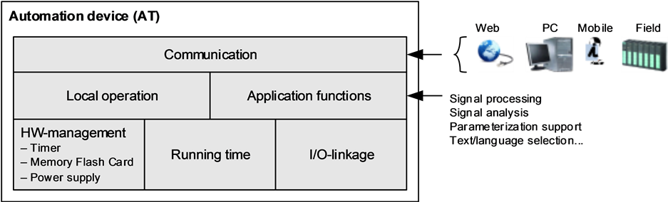
Figure 2. Typical components of an automation platform.

Figure 3. Life cycles of the different disciplines involved in the plant and product automation according to Li et al. [14] (different cycles in product automation).
These challenges, concerning the life-cycle-management, and the temporal dependencies in the life cycles have to be kept in mind during software engineering in order to support evolvable software over long time periods, i.e. 10 - 15 years and to support online changes at runtime.
The special skill of automation engineers lies in their ability to connect and integrate methods from other scientific disciplines to an integrative overall process for the development of industrial used technical systems. Thereby, the specific challenges of controlling highly critical technical processes have to be considered already in the engineering phase and appropriate and adjusted software engineering methods are necessary to deliver high-quality results.
Another essential basis of automation is the employment of models. Models are required for the conceptual design, implementation, testing, optimization and diagnosis of automation systems. Research in automation embraces models of various scientific disciplines, e.g. from computer science, and adapts them according to the needs of automation. However, designing software based on formal models is not yet common in the automation industry, albeit much research has been done regarding the generation of PLC code from formal models [2] .
For the design and realization (i.e. programming) of automation functions, diverse models and notations have been developed over the past decades or have been transferred and adapted from other disciplines. For example, Boolean algebra as well as automata theory were transferred from mathematics. From electrical engineering the circuit plan (Ladder Diagram [15] ) and the signal-oriented representation of function plans (Function Block Diagram [15] ) were adopted. An overview of the requirements for PLC programming and an evaluation of some notations has been developed by the “GMA”, the German national membership organization of “IFAC” [16] (see overview extended by UML derivatives, Table A1 in Appendix). The required characteristics of the models on the one hand, and the tools on the other hand, hence, are crucial for automation software engineering.
The efforts to introduce automation in production processes as well as in processes of other application areas have changed fundamentally over the last years. While in the beginning the focus was on the automation of fixed, recurring activities, today’s attempts try to assemble flexible systems for varying tasks. Next to the installation of automated systems, the automation of already existing, however not yet automated or merely semiautomated processes and activities is a major task of automation. For example, in case of errors in the production system or the automation system, changes in the software have to be performed by craftsmen, i.e. electricians during runtime; for instance, the setting of outputs and the bridging of sensor requests until a hardware defect is repaired by replacing a device, in order to keep the plant's downtime at minimum. Thus, the software engineering approaches need to be appropriate for craftsman, as well, or otherwise specific views and fault handling levels for craftsmen need to be added.
3. Challenges in Automation Software Engineering
The conditions of using software in plant automation and the basic relations lead to challenges for the software, the hardware, on which the software runs, and consequently the software engineering. These characteristics will be explained in this chapter in detail.
3.1. Usability Challenges
During the systems’ development, utilization and maintenance various user groups are involved. This requires software engineering to consider all different stakeholders and provide suitable integrated methods and processes. In detail, the following circumstances have to be considered:
Software engineering in automation contains several levels of software development: Generic basic modules are created independent from the specific projects by computer scientists or engineers with strong software engineering skills in nearly each company. These modules are then provided in a library for reuse. This group of developers commonly use high level and object oriented languages and model driven approaches. During automation engineering, the existing basic software modules have to be connected by engineers to build the application software. During the operation and maintenance, short-term changes have to be conducted mostly by customer technicians and crafters at site [17] .
For building applications, rather mechanical or electrical engineers are appointed. They use the generic basic modules and combine them by adopting the languages of [15] : for continuous control engineering, Continuous Function Charts (CFC) are often employed. For discrete control engineering, the Function Block Diagram (FBD) is wide-spread in Europe, whereas in the Americas, mainly the assembler-like Instruction List (IL) and the circuit diagram-like Ladder Diagram (LD) are in use (compare Figure 4). For complex control functions, designing the control code in MATLAB/Simulink is suitable, which has to be translated into IEC 61131-3 or C code afterwards. The Pascal-like language Structured Text has an increasing influence nowadays as well as objectoriented enhancements of IEC 61131-3. Due to several limitations of IEC 61131-3, the IEC 61499 standard, which offers an extension to the IEC 61131-3 Function Block Diagram, has been defined to improve the development of industrial systems. It is used by industrial groups as well as in the academic field and is classified as a basis for the development of best practices in industrial engineering, albeit its effectiveness has been criticized [7] .
Traditionally, a function-oriented design approach was used in PLC programming, but due to some limitations associated therewith, new approaches like object-oriented programming and aspect-oriented programming have been developed. Depending on the chosen design approach, different challenges regarding the usability have to be overcome [2] .
3.2. Changeability during Runtime
Changes during runtime are especially necessary in the process industry, i.e. chemical, petro-chemical and pharmaceutical industry. In the machineand plant-manufacturing industry the sub-system test in the factory of
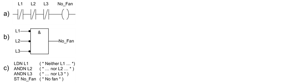
Figure 4. Examples of a) Ladder Diagram (LD), b) Function Block Diagram (FBD), and c) Instruction List (IL) of the 5 programming languages. Three fans (L1 to L3) are monitored refereeing to their malfunction (Lx = false). In case that none of the fans operates the signal no fan should be created and will be used for further failure handling.
the machine supplier is gaining more and more importance in order to reduce the commissioning and startup time on the construction site. The startup consists of an input-/output-check as well as the actual startup of the subsystems until the system integration test, which is completed through acceptance testing. As an essential functionality during the startup, the control code has to be adapted to the actual situation of plant and process. Regularly, the application engineer does not perform the startup himself (only in case of a prototype of a plant or plant section). During the operation and maintenance phase, the monitoring of variables and the online manipulation of the program, e.g. through forcing of variables, or the safe exchange of parts of the program and the safe change of the allocation of variables in the program, have to be supported. Thereby, also a multi-user-mode is necessary. For an efficient re-engineering or optimization of the plant, the capturing and analysis of already existing programs is essential. In order to control changes and manage different versions of a plant’s automation software, a number of different approaches in software configuration management have been taken (refer to Vyatkin [2] for a brief summary). The possibility of online-observation and -changes is a unique feature of a PLC in comparison to Industrial PCs (IPCs) using high-level language programming. The final test of the software of a plant is usually carried out on-site, to be able to include the boundary conditions, e.g. raw material, and to verify all aspects of the function, e.g. humidity, which is relevant for many processes, or the raw material for production.
3.3. Basic Automation Functions
There is a basic variety of automation functions, concerning measuring, open and closed-loop control. The automated process control requires additional functions like e.g. monitoring, archiving, alarming, manipulating and saving (for more details see Table A1 in Appendix).
In comparison to software systems in the automotive sector, in plant automation the operation modes constitute another orthogonal requirement [18] . While these operation modes have no significance in regard to embedded systems, as the embedding system, e.g. an automobile can in case of an occurring fault be stopped and the embedded system can be shut down or fall into a safety mode. In plant automation the operating personnel has to eliminate the source of the fault and bring the plant from manual mode or even after an emergency shutdown back into automatic mode and resume the operation. This requires for the software that automation functions and, therefore, most modules not only have to be operated in automatic mode but also in manual mode, if necessary with other signals, other operation controls and reduced speed. This as well as error handling has to be included in software engineering in automation [19] . Furthermore, a future challenge will be the appropriate support for the operators in case of failures, i.e. a stepwise trouble shooting assistance.
Additional system aspects have to be considered in the design of automation software, e.g. the causal and temporal associations, resulting from the automation-affected technical process and physical structure of the technical system (through material and energy flows as well as information that impacts these flows), have to be considered, in order to avoid undesirable side effects or even instabilities of the system. Also the characteristics of those components of the technical system that are directly relevant for the execution of automation functions (sensors, actuators, information processing devices, communication devices) have to be observed, for example with regard to signal propagation time, processing speed, computing and storage capacity, security and reliability to name only some. Moreover, the automation functions have to be highly adaptable by configuration and parameterization, in order to support reuse and achieve in this way the necessary economic quantity of the automation components.
3.4. Specific Platforms and Their Constraints
The successful realization of automation mainly depends on how the existing, re-engineered and new plants, machines and components can be transferred into a consolidated automation concept and automation architecture. Therefore, a software solution has to be provided, which integrates these systems and ensures the interoperability [20] of the existing heterogeneous software and hardware landscape. Specifically, the following challenges have to be considered:
There is a big variety of existing microcontrollers and real time operating systems. Up to now, there is no trend to standardization in this field of automation. Main reasons for that are the different functionalities embedded in the devices, reaching from primitive binary sensors to highly complex drives and analysis-devices. Thereby, the execution time of the function realization has to be observed according to the sampling theorem, as automation functions often affect time-continuous systems. Within one device, synchronous and asynchronous function executions are carried out in parallel and changes of the application functions during operation have to be supported.
Usually, several automation devices, connected by industrial communication systems, implement jointly a function within one cycle, e.g. a closed loop control. Thereby, deterministic industrial communication systems have to be used and synchronization across devices has to be realized within a µs to ms range to fulfill the real time requirements of automation systems.
The access to the automation functions during operation is conducted in parallel from different host-systems with different constraints regarding timing and functions (e.g. control parameterization and service or diagnosis). Thus, different Quality of Service (QoS) of the communication in the device, the concurrent access to the functions from different hosts and the handling of various functionalities through operators with different authorizations and qualifications are necessary as well as maintaining consistency of the automation function parameterization.
Moreover, in certain application areas, very high numerical calculation accuracy (e.g. calculation of the flow rate with 64-Bit floating-point numbers), the fulfillment of the functional safety, joint communicationand powerlines for devices and very long time in use (10 years and longer) are common and necessary (see Figure 3).
Domain specific languages for the configuration, parameterization and programming of automation devices are crucial for the operation in diverse application areas. In addition, the functional modularization and assignment to hierarchical levels in order to ensure determinism during execution despite the complex interrelations within very big systems (with more than 10.000 I/O-signals), is crucial. Furthermore, technologies to integrate automation devices and thus, ensure interoperability of the cooperating functions and very long time in use of the devices are of significant importance [21] .
Because most automation systems consist of distributed controllers (see Figure 1, right side) and are connected via communication networks in the design process the automation software need to be distributed to a specific controller guaranteeing the required constraints regarding Quality of Service, e.g. real time requirements. To support this complex task the FAVA approach has been developed [22] . Distributed automation systems are also focused by Vyatkin [23] .
3.5. Closed Loop Control and Real Time Behavior for a Safe and Secure Operation
Because the technical process in plant automation requires an openor closed-loop control, further requirements arise. Sensors give information about physical quantities of the technical process, which are gathered constantly by the automation software and processed with the goal to manipulate those (and, if required, also other) physical quantities through the actuators. In this loop (Figure 5) process signals are transferred typically between the automation device and the technical process via sensors, analogue-digital conversion, field bus systems and actuators loosing time and accuracy in each of the devices.
The described structure leads to some important extra functional requirements for automation software: the real-time capability is essential, as the physical surrounding cannot wait like a human user. Safety is another important criterion, since malfunctioning of the automated technical systems can cause enormous damages. A
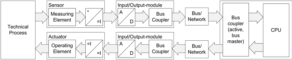
Figure 5. Transmission of process signals between the automation device (CPU, e.g. PLC) and the technical process [24] .
consequence of the described structure, which is often not realized directly, is the fundamental difference in the way requirements for this kind of automation software have to be acquired in comparison to requirement acquisition for “classical” software. In automation, the focus is not on the behavior of the intended software, but on the behavior of the technical system and the technical process that is automated with software (Figure 1). This is different from inclusion of the hardware, on which the software runs, as the behavior results from the dynamics of the influenced technical system, technical process and its feedback with the automation system and its software.
Most requirements, therefore, have to be acquired first for the entire system, from which the requirements for the automation software can be derived. For example, the requirements for a velocity control system for vehicles result from the quality criterion of the closed loop (e.g. maximum overshoot). The dynamics of the vehicle (“How big is the inertia due to the mass and possible influence through the motor and the brakes?”) are in opposition to those requirements. Only the joint analysis of both aspects, for which often models of the system have to be developed and analyzed, leads to the requirements for the software (e.g. that a PID control algorithm with certain parameters should be used or that a certain response time has to be met).
3.6. Life-Cycle-Management
In plant automation, especially in plant manufacturing, it is crucial to keep the downtime, caused by software changes, as low as possible or to completely avoid it. Thus, a requirement of automation is the ability to change the software during runtime, meaning during the operation of the plant, and also to replace parts of the hardware, e.g. sensors or actuators, during runtime as well as to ensure the compatibility of the software for respectively long periods (section 2).
As mentioned at the beginning, various components—hardware as well as software—act together in automation. Thereby, the life and innovation cycles of those components differ considerably. The time in use of a manufacturing system is very dependent on the industry sector. Ensuring the faultless functionality of the integrated components is a big challenge in plant automation, due to the shorter life cycles of the single components, especially the software components. Furthermore, the systems are constantly enhanced regarding their functionalities and price.
The generic life cycle model for automation, developed by [25] and currently in standardization by IEC, differentiates between types and instances of products. Thereby, a type defines a product, which fulfills specific requirements and is developed further through the integration of new functions or the introduction of new technologies. In this way, new versions with different characteristics are generated. Each manufactured unit of a certain type defines an instance and can be identified through an unambiguous identifier (e.g. serial number). Each instance of a product has a certain life time (Product Life Time), reaching from its creation to its disposal. For software products, this means that different versions have to be used and maintained in parallel. For this purpose, an accordingly powerful version management is required, which assigns unique version identifiers based on defined rules. For the definition of such a version-terminology, the compatibility of the components has to be taken into account. A compatibility model, based on [26] , is included in [25] . The focus of all stakeholders in the value chain on the life-cycle-management and the proactive consideration, beginning at the planning phase of a system, based on a common model, is essential to minimize the total cost of ownership (TCO).
3.7. Models in Automation
To support the engineering of automation systems, a multitude of kinds of models has been invented or derived from other scientific disciplines over the years. In general, the following partial models are required [27] :
1) Models of the system that shall be automated, describing its structure and behavior (dynamics);
2) Requirement model (concerning structural and dynamical, functional and extra functional requirements);
3) Models of existing automation (partial) solutions that should be used;
4) Procedural models for the engineering activities, i.e. the conception, definition and realization of automation systems;
5) Models of the overall automated system, including a verification in which way the requirements are satisfied;
The models interact as shown in Figure 6: Based on the models 1, 2 and 3 model 5 is developed through the application of the model 4. These models can have different degrees of formalization: informal, semi-formal and formal models are used [16] . The advantages of formal models, despite their analyzability, should always be set in contrast to the considerable effort of creating them for real systems.
Originally, a system’s mechanical, electrical and software parts are modelled separately and combined at the end of the modelling process. However, this approach is unfit to handle the complexity, dynamics and uncertainty of today’s automation plants. In order to enable synergetic modeling of mechatronic systems, models such as the SysML 3 + 1 view-model are in development. The SysML 3 + 1 view-model is an attempt to integrate modeling tools of the involved disciplines developing mechatronic systems i.e., IEC 61499 for software models and the Modelicamodelling language to represent a system’s mechanics (refer to Thramboulidisfor more details [7] ).
The models of category 1 (models of the system that shall be automated) and 2 (requirements) are provided by stakeholders outside the automation and computer science domain and are usually highly informal. A formalization can, due to time pressure in projects, not be enforced. Besides the necessary effort made by some researchers and safety critical or reliable systems Software Engineering for automation systems in general has to cope with these informal information sources.
3.8. Application of Tools in Software Engineering
The development and analysis of models (see 3.7) require appropriate software tools. A significant aspect is the coupling to the tools of mechanical and electrical engineering, as well as to the tools of preceding life cycle phases and, due to the necessity of changes during operation, also of subsequent phases, i.e. operation and maintenance. The model-driven engineering (MDE)-approaches, which are common in software engineering, with code generation and changes exclusively in the model, cannot be realized in plant automation [28] , because on construction sites worldwide changes in the code on the target platform have to be performed quickly, a consultation with a development department (in the worst case in New Zealand with a time difference of 12 hours) or a waiting period are not acceptable. For brief description of several software design approaches including
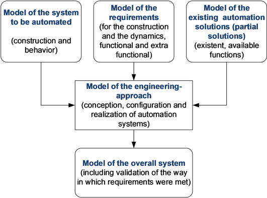
Figure 6. Creation of an overall system model for the automation software [27] .
areas such as architecture, methods, design strategies and evaluation notations, refer to [2] .
According to the extra functional requirements from the domain discussed in the previous sections the following requirements for tools have to be emphasized:
The tools have to be available for a long period of time (reliability → availability, maintainability, portability) and have to be tailored to the respective user groups (usability, functional suitability). They have to support a modular planningand development-process, as automation systems are a combination of pre-assembled (partial) systems. Thus, the tools have to support library concepts of component types (maintainability → reusability) and special configuration processes. Especially for the integrative and successful cooperation of all stakeholders the interoperability [29] of the used software tools and the support of a variantand version-management in terms of a life-cycle-management is essential.
Numerous developments from the area of mainstream software engineering (such as service-orientation or model-based engineering) have been adopted in the field of industrial automation. However, their relevance and applicability in plant automation is limited and the implementation of standardization is necessary to enhance their significance in industrial application [2] .
Also refer to Vyatkin [2] for an overview of current software approaches including requirements engineering as well as design strategies and construction issues.
4. Summary and Future Research Directions
This article gives an introduction to the essential challenges of software engineering and requirements that software has to fulfill in the domain of automation. Thereby, the functional characteristics, specific constraints and circumstances are considered for deriving requirements concerning usability, the technical process, the automation functions, used platform and the well-established models, which are described in detail. On the other hand, challenges result from the circumstances at different points in the single phases of the life cycle of the automated system. These requirements—namely requirements for life-cycle-management, tools and the changeability during runtime—are described in detail.
Many approaches from general software engineering, like object orientation or MDE-approaches, have already been incorporated into plant automation. However, they reach their limits, if they are not adapted to the specific requirements. Methods and modeling techniques from software engineering need to be studied and evaluated based on the discussed criteria regarding their applicability or needed adaptation for the automation domain. As one demonstrator for joined work, a simplified demonstrator has been developed providing many engineering documents [30] . Especially, management of variants and versions is still an open issue as well as interconnection and data exchange between models of software engineering in automation, mechanical engineering and electrical engineering, taking into account the interdependencies of different models in the case of change management. Work in this field is on the one hand focused on a German collaborative research area (SFB 768 [31] ) as well as on a priority program (SPP 1593 [32] ) including both researchers from software engineering and from automation.
References
- Göhner, P. (2013) Automation Technology I—Lecture Notes. Institute of Industrial Automation and Software Engineering, University of Stuttgart, Stuttgart.
- Vyatkin, V. (2013) Software Engineering in Factory and Energy Automation: State of the Art Review. IEEE Transactions on Industrial Informatics, 9, 1234-1249. http://dx.doi.org/10.1109/TII.2013.2258165
- Jooß, C., Vossen, R., Leisten, I. and Jeschke, S. (2012) Knowledge Engineering in Interdisciplinary Research Clusters. Proceedings of IEEE International Conference on Industrial Engineering and Engineering Management (IEEM), Hong Kong, 10-13 December 2012, 1845-1852.
- Jazdi, N., Maga, C. and Göhner, P. (2010) Improved Systematisation in Plant Engineering and Industrial Solutions Business—Increased Efficiency through Domain Engineering (Mehr Systematikfür den Anlagenbau und das industrielle Lösungsgeschäft—Gesteigerte Effizienzdurch Domain Engineering). Automation Technology (Automatisierungstechnik), 9, 524-532.
- Estévez, E., Marcos, M. and Orive, D. (2007) Automatic Generation of PLC Automation Projects from Component- Based Models. The International Journal of Advanced Manufacturing Technology, 35, 527-540. http://dx.doi.org/10.1007/s00170-007-1127-4
- Biffl, S., Schatten, A. and Zoitl, A. (2009) Integration of Heterogeneous Engineering Environments for the Automation Systems Lifecycle. IEEE International Conference on Industrial Informatics, Cardiff, 23-26 June 2009, 576-581.
- Thramboulidis, K. (2010) The 3+ 1 SysML View-Model in Model Integrated Mechatronics. Journal of Software Engineering and Applications, 3, 109-118.
- Vogel-Heuser, B., Braun, S., Kormann, B. and Friedrich, D. (2011) Implementation and Evaluation of UML as Modeling Notation in Object Oriented Software Engineering for Machine and Plant Automation. Proceedings of the 18th IFAC World Congress, 18, 9151-9157.
- International Electrotechnical Commission (2006) International Electrotechnical Vocabulary—Part 351: Control Technology. IEC Standard IEC 60050-351.
- Lauber, R. and Göhner, P. (1999) Prozessautomatisierung 1. Springer, Berlin.
- Maga, C., Jazdi, N. and Göhner, P. (2011) Requirements on Engineering Tools for Increasing Reuse in Industrial Automation. 16th IEEE International Conference on Emerging Technologies and Factory Automation (ETFA’11), Toulouse, 5-9 September 2011, 1-7.
- Yazdi, F., Vieritz, H., Jazdi, N., et al. (2011) A Concept for User-centered Development of Accessible User Interfaces for Industrial Automation Systems and Web Applications. International Conference on Universal Access in Human-Computer Interaction (UAHCI), Orlando, 9-14 July 2011, 301-310.
- NAMUR (2003) Handling PCT Projects. NAMUR Worksheet NA 35.
- Li, F., Bayrak, G., Kernschmidt, K. and Vogel-Heuser, B. (2012) Specification of the Requirements to Support Information Technology-Cycles in the Machine and Plant Manufacturing Industry. IFAC Symposium on Information Control Problems in Manufacturing (INCOM), Bukarest, 23-25 May 2012, 1077-1082.
- International Electrotechnical Commission (2009) Programmable Logic Controllers—Part 3: Programming Languages. IEC Standard 61131-3.
- Verein Deutscher Ingenieuree (2005) Classification and Evaluation of Description Methods in Automation and Control Technology. VDI/VDE Guideline 3681.
- Vogel-Heuser, B. (Ed.) (2009) Automation and Embedded Systems—Improvement of Efficiency in Engineering (Automation and Embedded Systems—Effizienzsteigerungim Engineering). Kassel University Press, Kassel.
- International Electrotechnical Commission (2010) Function Blocks (FB) for Process Control—Part 3: Electronic Device Description Language (EDDL). IEC Standard 61804-3.
- Feldmann, S., Fuchs, J. and Vogel-Heuser, B. (2012) Modularity, Variant and Version Management in Plant Automation—Future Challenges and State of the Art. International Design Conference (DESIGN), Dubrovnik, 21-24 May 2012, 1689-1698.
- Diedrich, C., Lüder, A. and Hundt, L. (2011) Importance of Interoperability within Engineering and Use of Automated Production Systems (Bedeutung der Interoperabilitätbei Entwurf und Nutzungautomatisierter Produktionssysteme). Automation Technology (Automatisierungstechnik), 59, 426-438.
- Diedrich, C. (2007) Integration Technologies of Field Devices in Distributed Control and Engineering Systems. In: Zurawski, R., Ed., The Industrial Information Technology Handbook, CRC Press, Boca Raton, 11.1-11.24.
- Frank, T., Hadlich, T., Eckert, K., Diedrich, C., Fay, A. and Vogel-Heuser, B. (2012) Using Contact Points to Integrate Discipline Spanning Real-Time Requirements in Modeling Networked Automation Systems for Manufacturing Systems. IEEE International Conference on Automation Science and Engineering (CASE), Seoul, 20-24 August 2012, 851-856. http://dx.doi.org/10.1109/CoASE.2012.6386422
- Vyatkin, V. (2011) IEC 61499 as Enabler of Distributed and Intelligent Automation: State of the Art Review. IEEE Transactions on Industrial Informatics, 7, 768-781.
- Vogel-Heuser, B., Feldmann, S., Werner, T. and Diedrich, C. (2011) Modeling Network Architecture and Time Behavior of Distributed Control Systems in Industrial Plant Automation. Annual Conference of the IEEE Industrial Electronics Society (IECON), Melbourne, 7-10 November 2011, 2232-2237.
- Zentralverband Elektrotechnik-und Elektronikindustrie (2012) Life-Cycle-Management for Automation Products and Systems. http://www.zvei.org/Verband/Publikationen/Seiten/Guideline-Life-Cycle.aspx
- International Electrotechnical Commission (2007) Obsolescence Management—Application Guide. IEC Standard 62402.
- Fay, A. (2011) The Role of Models in the Engineering of Automation Systems. Workshop on Model Integrated Mechatronics, Saarbrücken.
- Vogel-Heuser, B., Braun, S. and Kormann, B. (2011) Implementation and Evaluation of UML as Modeling Notation in Object Oriented Software Engineering for Machine and Plant Automation. IFAC World Congress, 18, 9151-9157.
- Barth, M., Drath, R., Fay, A., et al. (2012) Evaluation of the Openness of Automation Tools for Interoperability in Engineering Tool Chains. IEEE International Conference on Emerging Technologies and Factory Automation (ETFA), Krakow, 17-21 September 2012, 1-8.
- Vogel-Heuser, B., Legat, C., Folmer, J. and Feldmann, S. (2014) Researching Evolution in Industrial Plant Automation: Scenarios and Documentation of the Pick and Place Unit. Technical Report No.TUM-AIS-TR-01-14-02. https://mediatum.ub.tum.de/node?id=1208973
- SFB 768 Managing Cycles in Innovation Processes. http://www.sfb768.tum.de/index.php?id=5&L=1
- DFG Priority Programme 1593. Design for Future—Managed Software Evolution. http://www.dfg-spp1593.de/
Appendix

Table A1. Aspects of automation functions (DE-domain expert).