Engineering
Vol.4 No.12(2012), Article ID:25867,4 pages DOI:10.4236/eng.2012.412116
PC-Based Automated Control System for Jordan Northern Grain Silo
Department of Computer Engineering, German Jordanian University, Amman, Jordan
Email: alagtash@gju.edu.jo
Received August 22, 2012; revised September 20, 2012; accepted September 30, 2012
Keywords: PC Based Automated Control System; PLC; Grain Silo; Bus Control Topology
ABSTRACT
This paper presents a PC-based automated control system operation of the Northern Grain Silo of Jordan. The system connects to a PLC (programmable logic controller) device, and combines operator interface, PLC programming and monitoring functions into one platform. The PLC portion handles direct operations control, while the PC portion handles interfacing and data intensive functions. A simulation package is developed. The package generates a graphical user interface for real-time graphic animations of the Grain Silo operation. We discuss anticipated benefits of such a system and phases of implementation.
1. Introduction
Programmable logic controller (PLC) has long been a major technology of automation in the industrial control market. It has evolved from the need for a control system that can be easily reprogrammed as changes occur or as new products are developed. The principle of PLC is based on the concept of a sequential control process. The operation of a specific device is dependent on a sequence of operations and conditions of other devices. The control process is reprogrammable or reconfigurable using a microprocessor-based electronic device. PLCs have been perceived faster and more reliable than running control software on an embedded personal computer (PC). The benefits of the PC based control system, however, are significant. In addition to control operations, they share data and can combine operator interface, data filing, programming, diagnosis, and monitoring and control functions into one platform.
The PC-based control system has recently gained popularity in the industrial automation market [1-6]. Microsoft’s Windows operating system is a leading choice for many developers of software-based industrial controllers. Windows supports a broad base of applications and simplifies data sharing. Developing Windows/PCbased control systems with real-time, deterministic performance is still a challenge [7,8]. Software-based control logic needs to perform a control operation at precisely the time requested. Within the operating requirements of typical PC operating systems, this is pretty difficult. PCs typically process multiple control and data intensive functions while transferring and displaying data through a graphical user interface. Combining those functions with real-time control has not been possible. The best approach is an integrated system of PLC and PC. The PLC is either a board that can be plugged into the PC, or a separate device that can be connected to the PC via I/O modules. The PLC portion handles direct control of a process while the PC portion handles all data intensive functions.
The northern grain silo of Jordan is in the process of moving towards a PC-based control environment to meet expanding market and administrative requirements in an era of information technology. A grain silo is a storage media of grain. Huge amounts of grain are reserved to meet daily market needs in the area. The silo consists of a number of large cylindrical storage cells. Each cell is about 50 meters high and 10 meters radius. There exists a complex control system to manage the storage and distribution processes of the grain. There are two different control systems for different sets of grain cells. One is the manual control system that uses hardwired relay system. The system is operated manually through a control panel in the control room. The panel mainly consists of switches and pushbuttons to remotely operate motors, conveyers, lifters, etc. The panel also consists of light indicators to monitor the system operation. The second control system is the PLC automated system. The PLC has many advantages. The control process is easily reconfigurable as changes occur. The system does not allow the operator to manually operate the system devices, thus a wrong selection in the operation sequence is not possible. The only disadvantage is the complexity involved, a fact that requires highly skilled personal. The two systems are totally decoupled. Recently, considerable efforts are being devoted to couple the two systems and to develop programming, monitoring and diagnosis interfaces that require less skilled personal.
This paper presents a design framework of a PC-based automated control system for the Northern Grain Silo of Jordan. The system connects to a PLC (programmable logic controller) device, and combines operator interface, PLC programming and monitoring functions into one platform. A simulation package is developed using Visual C++ under Microsoft developer studio. The package generates a graphical user interface for PLC programming and provides real-time animations of the Grain Silo operation. The package runs a small-scale grain silo operating on a basis of PLC automation. It shows graphics of storage cells, conveyer belts, operation sequencing, and grain distribution. The system motors, conveyers, grain cells, switches, and sensors are connected to the PLC through input/output interfacing modules. The package provides validation and testing platforms for future implementation of our design. We use Object oriented Programming (OOP) for design and implementation. The OOP furnishes designers with powerful features to model complex data and applications, [9]. Abstraction, modularity, polymorphism, encapsulation, exception handling, fault tolerance and many other adept features greatly enhance performance and allow easy integration with existing proprietary software. The remainder of the paper is organized as follows: Section 2 presents the proposed grain silo automated control system. Section 3 presents software implementation. Testing results are discussed in Section 4. Finally, the main conclusions are given in Section 5.
2. Grain Silo Automated Control System
An overview of the operation and information flow of the proposed grain silo automated control system is shown in
Figure 1. The system handles direct control through the PLC and collects real-time data for monitoring, fault diagnosis and management planning. The operator issues a production plan (i.e. scheduled grain-in/out, grain cell operation, etc.). The plan is decoded into a PLC program, then transferred to the control server (CS). The international IEC 1131.3 specification for PLC programming languages defines four programming standards: ladder-logic diagrams, function-block diagrams, instruction list and structured text [10]. We use ladder-logic diagram for PLC programming. The CS downloads the decoded plan into the PLC. The PLC implements direct system controls through several input/output modules. The PLC and data sensors gather information on the system status. The CS then uses this information for monitoring, diagnosis, and data analysis. Different PC terminals connect to the CS through a BUS control topology. The information flow can be an Intranet or the Internet. The Internet covers a broad range of users and gives access to remote management personal from the ministry of industry and commerce.
Control server architecture
The control server is an automated interface component between system users and the grain silo plant. The operator establishes a connection with the server over the network for monitoring or programming. The server has direct access to the network API (application programming interface). This alleviates the complexity involved in network programming and deems the addition of services much easier and less error prone. The software architecture is shown in Figure 2. The modules represent components of separate functional entities. The PLC programming module allows the operator to program a production plan or a control process.
The programming language is the Ladder logic diagram. It gained popularity among the other PLC programming languages in the control industry. The translator module translates the Ladder logic into a machine code, then downloaded through the communication portsto the PLC. The monitoring module receives information on the status of the grain silo system. More details on these modules are given next.
The PLC programming module: generates a ladder
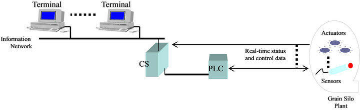
Figure 1. Proposed grain silo automated control system.
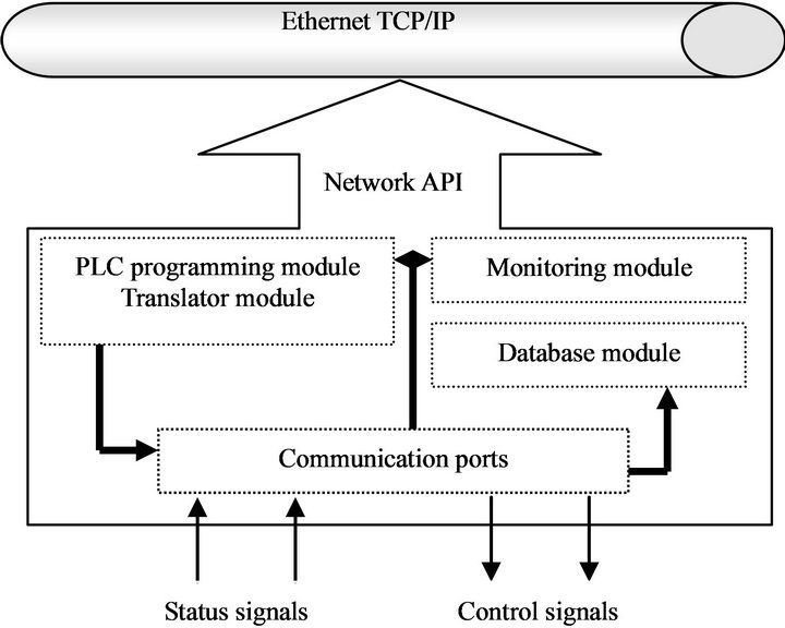
Figure 2. Software architecture of the control server.
logic diagram. The diagram is a programming environment that creates a virtual electrical system of wired devices. The outputs are on/off signals to motors, solenoids, indicator lights, etc. The inputs are DC or AC signals from the system interface switches, motion limit switches, sensors, etc. Circuits are arranged as a series of horizontal lines containing inputs (contacts) and outputs (coils). The input must precede the output and can be, for instance, normally open or normally closed contacts. Circuits in the form of vertical lines are not used. The numerical assignments for the inputs and outputs form part of the ladder diagram.
The output of the ladder diagram depends on the logic Boolean operators: AND-OR operators. The ladder ring may contain one or more than one operator. Each ring in the ladder diagram has an output to control a relay. CR1 (control relay number 1), for instance, controls the operation of motor m1. A ladder diagram editor is designed. The operator can drag components from a menu, then can construct ladder logic to accomplish a specific control task. Once a ladder diagram is constructed, it is translated into a machine code to run on the PLC. The ladder diagram may be reconstructed (reprogrammed) for different control tasks. Software implementation of this module is described in the next Section.
Grain silo monitoring module: The main elements of this module are: a temporary storage media, a motor to pull up the grain, grain cells, conveyers, sensors and lifters. The cells are the main storage elements, where the grain is stored for long term. The activities of pulling the grain, filling the cells, emptying the cell and exporting the grain are related to the system elements. Opening the cell door depends on an electrical signal from a switch to activate a solenoid. Emptying the cell is initiated when a sensor under the cell door on the ground senses a vehicle. This inhibits the door solenoid to be activated to open the door. The level of the grain in the well and in each cell is determined by using level sensors. Graphical objects are constructed for each of these elements. Fixed objects are constructed using bitmap format while animated objects are constructed using Cbitmap objects.
Grain silo database module: The module maintains statistical data on grain type, storage, distribution, and other related plant data. The entities of the database are cells, wells, vehicles and site. The cell entity is described by the cell Id, grain type, grain level, grain temperature, and sensor state. The well entity describes the grain level. The vehicle entity has three attributes: the name, size, and state. The site entity attributes are: name, address, type of the site (export or import), and quantity of grains, and time and date.
3. Software Implementation
Object oriented programming is used for design and implementation. It has many powerful features such as abstraction, encapsulation, polymorphism, and protection. The main component of the software is the control server and has three main software modules, each representing an encapsulated object within the package.
3.1. PLC Programming Module
This module has several objects as highlighted below with brief comments:
CHorizontalLine: connects the components with each other.
CNormallyOpenSwitch: when the user drags this element to the ladder ring, a dialog box appears and requires an input name, either Inputxx or CRxx, defined as follows:
Inputxx: the input value of the normally open switch. Where xx denotes the input number.
Crxx: the input value of the normally open switch feedback from an output of a previous control relay. Where xx denotes the number of the control relay.
CNormallyCloseSwitch: when the user drags this element to the ladder ring, a dialog box appears and requires an input name , either Inputxx or CRxx, defined as follows:
Inputxx: the input value of the normally close switch and depends on a state of a certain sensor. Where xx denotes the input number.
Crxx: the input value of the normally open switch feedback from an output of a previous control relay. Where xx denotes the number of the control relay.
CVerticalLine: this component represents an OR operator in the ring.
CTimer: is used for time delay.
CControlRelay: each ring ends with a control relay. The output name must be specified in the dialog box of the relay as:
Crxx: represents a control relay with number xx.
Mxx: a motor with number xx.
These objects constitute the main class elements of the ladder package.
3.2. Grain Silo Monitoring Module
The main elements of the grain silo monitoring module are converted into three programming objects: CgrainSiloView, CwellView, and CcellView. The CGrainSiloView generates the main view of the grain silo that includes the elements: cells, wells, conveyers, lifters, motors, sensors and vehicle. From this view, we can monitor the flow of the grain from the well into the cells, and from the cell into the vehicles. The CwellView generates the view of the well showing grain level and sensor state. Finally, the CCellView generates a view of eight cells displaying each cell state, sensors, grain levels, and operating motors.
The graphical elements of the package are based on bitmap objects. The fixed graph that is not altered is loaded as a bitmap image for the simplicity of code saving. On the other hand, graphical elements that need to be animated (e.g. grain) are constructed using CBitmap object. The object is drawn into a memory device and the contents are copies into a client area. This supports code reusability and object animation. Redrawing and translating the animated object does the animation of the object. Different programming options are available for animation. One is the SDI (single document interface) which provides one view of the application linked with one document. A second option is the MDI (multiple document interface) which provides multiple views arranged with multiple documents. In our simulation, every document presents a view. A third option is to have multiple views with one document interface (MVSDI). The distributed library of the VC++ provides a function that supports multiple view single document objectives. We next give a snapshot of the code implemented. The CGrainSiloApp::InitInstance( ) function replaces the code that registers the application’s document templates. Document templates serve as the connection between documents, frame windows and views:
CMultiDocTemplate* pDocTemplate;
pDocTemplate = new CMultiDocTemplate(IDR_ GrainStype,
Runtime_Class(CGrainSiloDoc),
Runtime_Class(CChildFrame), // custom MDI child frame
Runtime_Class(CGrainSiloView));
The following code registers one document for the grain silo view:
CMvDocTemplate *pDocTemplate = new CsdimvDocTemplate( IDR_Grainstype , Runtime_Class( C GrainSiloDoc ) );
pDocTemplate- > AddFrameTemplate(new CFrameTemplate(IDR_GRAINSTYPE,
Runtime_Class( CChildFrame ),
Runtime_Class(CGrainSiloView),
// Grain silo view
ID_FILE_NEW, SW_ShowNormal, TRUE) );
Where CMvDocTemplate represents a base class for the doc template and is derived from CMutiDocTemplate. It manages a document manager instance for each document open; CSDIMVDocTemplate represents a single document interface class, derived from CMVDocTemplate. This class manages a single document file and all multiple view processing; AddFrameTemplate is used to add a specific frame template to a specific document. CframeTemplate defines each specific frame associated with a document template. To display a specific window, it requires a resource id, frame runtime class (RTC), RTC view and event ID. Similarly, calling CWellView and CCellView functions generate Well and Cell views.
3.3. Grain Silo Database Module
The database is designed in the SQL Server manager. The server accesses the database using the ODBC (open database connectivity) method or using ActiveX data objects (ADO). ODBC gives the programmer an easy way to access the contents of the database. The two mechanisms are available in the MFC (Microsoft Foundation Class) libraries. Figure 3 shows a block diagram of the database connectivity model. A 32-bit ODBC applet data source is created in the control panel. To establish the database connectivity, the data source name and description and the database file name are entered in the SQL server setup dialog box.
3.4. Inter-Parallelism
To accomplish robust, fast and efficient automated con-
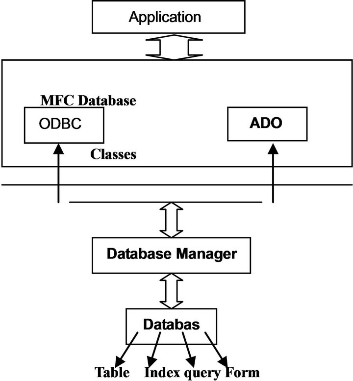
Figure 3. A block diagram of the database connectivity model.
trol process, the software is built multithreaded. This provides an opportunity for inter-parallelism in a multiprocessor platform. There are two techniques to achieve parallelism in one-processor platforms:
Virtual multiprocessing: this is implemented using virtual processes. Each virtual process is a collection of virtual memory space code, data, and system resources. Processes communicate with each other through massages using a specific function to pass information. A process function is created to fork a new process on its primary thread. The new process executes the specified executable file and runs independently of the created process.
Shared memory: this is implemented with file mapping. It supports security access attributes and can only operate between processes running on the same computer.
In the simulation package developed, file mapping is used to map a block of named-shared memory into the virtual address space of each process. To do this, the entry point function includes:
- Call the CreateFileMapping function to get a handle to a file-mapping object.
- Call the MapViewofFile function to map a view into the virtual address space.
4. Testing Results
A simulation package is developed using Visual C++ under Microsoft developer studio. The package utilizes the Microsoft Foundation Classes for reuse and standardization. The user initiates the simulation. The grain silo operation responds to the sensors status and the PLC programming logic. Upon initialization, the code forks two processes: one for the grain silo simulation and the other for the ladder diagram logic. The ladder diagram process output affects series of operations in the Grain Silo process. The two processes must, thus, work at the same time and this is achieved through shared memory parallelism. Figure 4 shows a sample of the implemented ladder logic and simulation graphics of two cells and a well of the grain silo plant.
Operation sequence:
The sequence of the grain silo operation is controlled by the PLC logic programmed using the ladder diagram editor. The simulation begins to fill a well randomly. The well has two sensors: low level (ll.w) and high level well (hl.w) sensors (limit switches). (hl.w) and (ll.w) are normally open (NO), thus they will be open until they sense grain, then will be closed. The first rung of the ladder contains the start switch (input1) and the stop switch (input2).
The simulation program is in the start position by a button click. The (cr1) will then be energized until a stop button is clicked in the simulation program. The second rung is related to the well sensors. A lifter is wrapped around the motor. If the motor is started, it will move the lifter with the grain on it. There is a sensor on the lifter (l.s1). All these are manipulated in rung4. motor (m1) contact is closed as a result of rung3. After a time T of energizing (m1) and when the grain reaches the sensor (l.s1), close (input 5) on the ladder diagram and the (cr3) control relay will be energized. In rung5, motor (m2) will be energized as a result of closing (cr3).
Motor m2 moves a conveyer to the next point where (m3) is located. Rung7 describes the starting of the motor (m3), as a result of closing the contact (cr4). Motor m3 moves a lifter to lift the grain to the top of the cell. Rung9 describes the starting of the motor (m4), as a result of closing contact (cr5). Motor (m4) contact is closed, and if sensor (sc1) is closed as a result of two conditions: reaching the grain near to the hole of the cell, the cell is not full; i.e. the NC sensor (hl.c) is not open. then the control relay (cr6) will be energized. This control relay will energize a solenoid (sol1). The solenoid is the device that opens the door of the cell.
If the cell is full, the sensor (hl.c1) will be open so control relay (cr6) will be de-energized, so that the motor (m5) will then stop working. Motor (m4) moves the grain until it reachs the sensor of the next cell (sc2). This process is applied to each cell in the grain silo plant. The ladder logic is then translated into a PLC code, and downloaded to the PLC for real-time implementation.
5. Conclusion
This paper presents a design framework of a PC-based automated control system for Jordan northern grain silo. The system handles direct controls through the PLC and combines operator interface, PLC programming and monitoring functions into a Control Server. Different PC terminals access the server through a TCP/IP Ethernet network. A software package is developed. It runs a smallscale grain-silo on a basis of PLC. In the second phase of the project, remote-interfacing tools will be developed to access the CS using Java applets or simply the Internet browser plug-ins. In addition, it is intended to develop a grain-silo prototype that connects to the CS and PLC for testing and validation purposes. A blended system of PC and PLC can apply to many industrial control systems. The benefits of such a system are tremendous. In addition to multiple control operations, data filing and analysis, PLC programming and system monitoring and diagnosis can be easily implemented.
6. Acknowledgements
This work has been initiated through a training and consulting service organized by the consulting and community service center at Yarmouk University with the Northern Grain Silo in 2000. The author would like to ac-
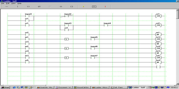
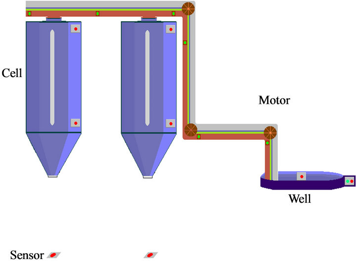
Figure 4. Ladder logic and simulation graphics of two cells and a well of the grain silo plant.
knowledge the technical support of the staff of the Northern Grain Silo in Jordan, and the software implementation of the simulation package of Nihal ElZubaidi and Tuqa ElManasra.
REFERENCES
- C. Bernard, “Embedded Systems,” Electronic Engineering Times, No. 858, 1995, pp. 41-46.
- J. Child, “Ethernet, Windows, and Web Technology Invade the Factory Floor,” Electronic Design, Vol. 47, No. 15, 1999, pp. 9-11.
- K. Hong, K. Choi, J. Kim and S. Lee, “A PC-Based Open Robot Control System: PC-ORC,” Robotics and Computer Integrated Manufacturing, Vol. 17, No. 4, 2001, pp. 355-365. doi:10.1016/S0736-5845(01)00010-2
- N. Konish and R. Gawel, “Factory Foremen Make Call for PC-Control Systems,” Electronic Design, Vol. 47, No. 20, 1999, p. 32A.
- M. Nor and K Cheng, “Development of a PC-Based Control System for a Five-Axis Ultra-Precision Micro-Milling Machine ‘Ultra-Mill’ and Its Performance Assessment,” Journal of Engineering Manufacture, Vol. 224, No. 11, 2010, pp. 1631-1644. doi:10.1243/09544054JEM1922
- K. Phillips and M. Gibson, “Internet Technology Aids Plant Operations,” Power Engineering, Vol. 102, No. 8, 1998, pp. 41-43.
- R. Garber, “The PLC versus the PC,” Forbes, Vol. 160, No. 5, 1997, pp. 198.
- G. Schwind, “PCs to Sweep PLCs,” Material Handling Engineering Journal, Vol. 52, No. 10, 1997, pp. 20-21.
- C. M. Davidson, J. McWhinnie and M. Mannion, “Introducing Object Oriented Methods to PLC Software Design,” Proceedings of the International Conference and Workshop: Engineering of Computer-Based Systems, Jerusalem, 30 March-31 April 1998.
- W. Bolton Newnes, “Programmable Logic Controllers: An Introduction,” Newnes, 1997.
NOTES
*Salem Al-Agtash received his Ph.D. degree in electrical engineering from University of Colorado in 1998. He is now an associate professor of Computer Engineering at German Jordanian University. His areas of interest are engineering system analysis, software applications, electricity systems, and intelligent control systems.