Materials Sciences and Applications
Vol.5 No.5(2014), Article ID:45552,9 pages DOI:10.4236/msa.2014.55039
Piezoelectric Ceramic Controlled with Platinum Implant as New Isolator in ECG
Ernesto Suaste-Gómez, Carlos O. González Morán, Omar Terán-Jiménez, Héctor Reyes-Cruz
Electrical Engineering, Bioelectronics, Centro de Investigación y de Estudios Avanzados del IPN (CINVESTAV—IPN), Mexico City, Mexico
Email: esuaste@cinvestav.mx
Copyright © 2014 by authors and Scientific Research Publishing Inc.
This work is licensed under the Creative Commons Attribution International License (CC BY).
http://creativecommons.org/licenses/by/4.0/


Received 11 January 2014; revised 2 March 2014; accepted 26 March 2014
ABSTRACT
Recently, a new PLZT bulk single plate, called ceramic-controlled piezoelectric with two Platinum wires (CCP2) has been produced; this CCP2 has two (250 µm of diameter and 1 cm long) Platinumwire implants. This unconventional isolation device for use with diagnostic ECG devices provides high common mode rejection and low leakage current using piezo isolator based on two Platinum wires implanted Lead Lanthanum Zirconate Titanate bulk ceramic. These isolation was validated using four experimental setups; one of them determine that ceramic-controlled piezoelectric with two Platinum wires (CCP2) support up to 6 kV DC before it cracks (short cut). The second experimental setup determined high resistance about 3.9 × 10⁹ Ω and 1.8 × 10⁹ Ω measured on lateral sides and among Platinum wires of CCP2 respectively. The third experimental setup was to obtain the current leakage from CCP2 and it was 6 nA. The fourth experimental setup was to obtain frequency response that was the maximum up to 2.2 MHz and was a pass band filter. Finally the CCP2 was applied as new isolator in a ECG circuit, where bioelectrical ECG signal is modulating at 16 KHz using the piezoelectric effect obtaining excellent results.
Keywords:ECG Piezo Isolators, PLZT-Platinum Wire Implanted Ceramics, Unconventional Device

1. Introduction
Progress in science and engineering goes hand in hand; science advances often depend on tools developed by engineers and reciprocally scientific knowledge guides and permeates engineering designs. Nowadays, it is not unusual to find engineers working with medical doctors and researchers in the design of artifacts that aim to improve human health [1] . The present paper relates to Electrocardiographic (ECG) signals, and in particular to an ECG device which utilizes a new piezo isolation with a PLZT ceramic implanted with two Platinum wires in a differential way to provide a safe, simple, reliable, and efficient means of extracting ECG signal information.
Among piezoelectric materials, Lead Lanthanum Zirconate Titanate (PLZT) is one of the most popular. PLZT is a ferroelectric solid solution with wide-ranging material properties that depend on its composition [2] . Recently, a new PLZT bulk single plate, called ceramic-controlled piezoelectric with two Platinum wires (CCP2) has been produced; this CCP2 has two, 250 µm of diameter and 1 cm long, Pt-wire implants in order to form a free upper and lower faces which measures electric events. The sample preparation is described in the following sections [3] . This structure design includes a differential electrode configuration due to Pt-wires introduced into a bulk PLZT. The Pt-wire was chosen as an implant because it possesses high resistance to chemical attack, it has excellent high-temperature characteristics (melting point 1768.3˚C), and it has stable electrical properties and thermal conductivity with small variations [4] . When CCP2 is polarized, the mobile charges in the Pt-wire accumulate on its surface until the field produced completely cancels the external field applied to the conductor; this results in electrical equilibrium within the Pt-wire thereby the internal the electrical field is zero, ε = 0 [5] .
Considering that ferroelectric and piezoelectric materials can be used as sensors, actuators, piezoelectric pressure and acceleration sensors, as well as a variety of piezo-vibrators, they are now commercially available [6] [7] . Among piezoelectric ceramics, CCP2 as well as CCP develops a singular performance due to the domain’s coating on Pt-wire; these concentrations achieve free flux charges around Pt-wire when CCP2 and CCP are excited by stress or laser illumination; this offers a great variety of applications in medical physics and biomedical engineering such as in this work the CCP2 is named: New Piezoelectric Differential Isolator (NPDI) [8] -[11] .
On the other hand, isolation circuitry for use with diagnostic ECG devices provides high common mode rejection and low leakage current using unconventional piezo isolators in conjunction with an operational amplifier. The output from the NPDI may be coupled directly to a recording device or coupled to a circuit which processes the ECG signal before the signal is recorded [12] .
Electrocardiograph electrodes are attached at desired locations on the body and the electrical activity generated by contractions of the muscle heart, as measured on the electrode leads, is connected to and recorded on an electrocardiograph in a conventional manner [13] [14] . However, because the signal thus generated are typically at low voltage levels, amplifier circuits coupled to the electrodes are needed in order to prevent masking of the signals by other extraneous electrical signal (noise). One technique known in the art for providing this amplifying function is to use an instrumentation amplifier. A differential amplifier measures only the difference between two input signals. Thus, if a common background signal is present in both input signals, the background signal will not be amplified because it is not part of the difference between the two input signals, but rather presents a common signal to both input signals. The differential amplifier advantageously amplifies this ECG potential difference to a much greater degree than other common mode signals that are present, such as the 60 Hz power line signal that are commonly induced in the body [15] . Another technique used for reducing the effect of external noise signals on the measured heart signal in modern ECG is to utilize multiple transformers on each electrode lead in conjunction with an applied carrier frequency in order to achieve a high common mode rejection and a high isolation factor. Over-voltage discharge elements are also utilized to protect the circuitry against high voltages, which high voltages may be present in the event a defibrillator device is used on the patient. The American Heart Association Committee on Electrocardiography believes that all ECG and Vectocardiographic (VCG) apparatus must be incapable of delivering more than 10 µA of leakage current to a patient [16] . This magnitude of current is consistent with data from human and animal experiments [17] -[20] .
A high isolation factor is necessary to both protect the patient if the patient inadvertently is connected to ground or a high potential, because the patient could suffer a electric shock and this can cause pain, jury or death, such as a power line and in order to achieve an improved high common mode rejection of extraneous signals thereby allowing the ECG signal to be more cleanly amplified and recorded or display. Although the use of transformers on each patient lead provides a circuit having high common mode rejection and a high isolation factor, the transformers are expensive, bulky, and tend to be unreliable [20] [21] . On the other hand, all optoisolators will only work up to a certain frequency up to 100 KHz. However, the intermediate frequency gain is not constant, and there is a curved portion in the frequency response [22] . Accordingly, what is needed is to provide an improved device for use with ECG devices that provides high common mode rejection, a high isolation factor (has low leakage current), and that is reliable, compact, safety and relatively inexpensive such as NPDI. This NPDI is also utilized in the constructed device of the present work. It is a new device used for the electrical isolation of the patient, which would provide the patient electrical safety in case of any malfunction in the electrical network.
The objective of this work is for demonstrating the isolation effect of NPDI in four experimental setups and getting an isolated EGC signal. The first experimental setup was to determine isolation voltage. The second was to determine high resistance of NPDI. The third was to determine its low leakage current and the fourth was to obtain frequency response. With it proves that the NPDI is a device which ensures the safety of a patient connected to a recording device of biopotential (ECG).
2. Methodology
A ferroelectric PLZT was chosen; this is a  ceramic with x = 0.09 and y = 0.35
(PLZT), generally denoted as (9/65/35). This ceramic was produced by the oxide-mixing technique: the raw materials were mixed by ball-milling with an electronic mill (Pulverisette 2, Fritsch) for 20 min; polyvinyl alcohol drops were added with a rate of 1.5 drops per gram of mixture. Powders then were pressed into discs of 10 mm diameter and 2 mm of thickness; the pressure applied was 3500 Kg/cm2.
During this process, two Pt-wires of 0.25 mm diameter (Aldrich 349402) were implanted in the middle of the ceramic in a longitudinal way separated each from other 2 mm in a parallel form; thus Platinum electrodes totally immersed in the ceramic was created. This ceramic was sintered in air with a heater ramp rate of 5˚C/min from room temperature to 600˚C and a second heater ramp rate of 10˚C/min from 600˚C to 1200˚C; the latter process lasted for one hour in a Platinum crucible. After sinterization, silver electrodes were deposited on the lower and upper face and on the Pt-wires of the CCP2. Finally, the discs were electrically poled to 1.5 kV/mm of voltage for one hour at 60˚C in a silicone oil bath. The schematic symbol used for describing the CCP2 and the graphical symbol can be seen in Figure 1.
3. Experimental Setups
To validate and determine electrical isolation characteristics of the NPDI before ECG signal acquisition, four experimental setups (high voltage, dc resistance, leakage current and frequency response) were used. In the first setup NPDI was submitted to an isolation test by means of applied DC electric field through pt-wires and one lateral face as follows: a DC high field supply was connected to a distance of 700 µm between implant and lateral face; NPDI was immersed into silicone oil bath in order to eliminate any sparks and the electric field was increased with a ramp rate of 500 V/min. A high voltage probe connected to a voltmeter was used for monitoring until ceramic fails (short circuit), as shown in Figure 2.
The second experimental setup has been realized with a collaboration of the National Metrology Center (CENAM, México) to determinate resistance values from different parts of NPDI as shown in Figure 3.
This model helps to us measure in continuous current (cc) represented by means of a setup series-parallel of RLC circuits.
According the CENAM procedures that established to determine different resistance values in order to inspect the NPDI resistance, this procedure uses an electrometer Mod. 6517 B (Keithley). The measure temperature was 24 ± 1˚C, the Humidity was 50% - 70%. To measure NPDI among A, B, C, and D places, a chamber was constructed with some special characteristics such as PTFE (Teflon) material that help to reduce bias currents, High purity coaxial cables of 40 cm long with Teflon isolation, Silver soldering, thermocouple to measure the internal chamber temperature and a metallic cage to isolate electromagnetically the Teflon chamber (as Faraday cage). The Teflon chamber is showed in Figure 4.
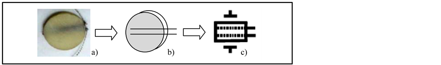
Figure 1. a) Photograph, b) schematic and c) new graphical symbol of CCP2 or NPDI based on PLZT. On graphical symbol can be seen lateral and internal electrodes.
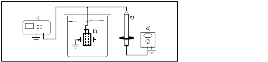
Figure 2. High voltage measured in an experimental setup to determine isolation level of NPDI. a) High voltage supply, b) NPDI immersed into silicone oil bath, c) High Voltage Probe, d) Voltmeter.

Figure 3. Scheme of NPDI and four resistance parts. a), b) represents lateral sides of NPDI (upper and lower respectively) and c), d) represents internal Ptwires.
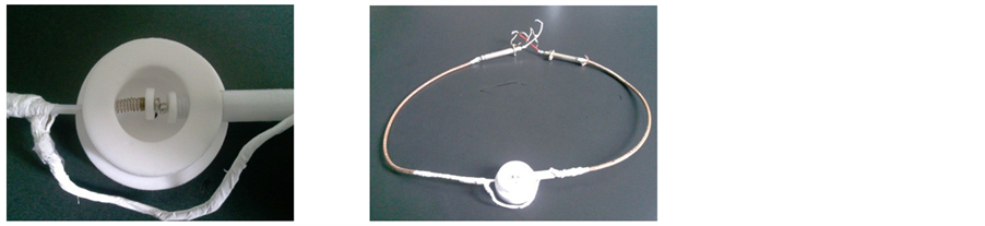
Figure 4. The Teflon chamber is connected to the NPDI with its coaxial cables.
The third experimental setup in Figure 5 shows the test configuration for the NPDI leakage test. The instrument sources the test voltage across the capacitor, and it measures the resulting leakage current through the device. The resistor, R, is included for current limiting, and it also helps to reduce noise. A typical value for R is 1 MΩ, although that value can be decreased for larger capacitor values of NPDI.
To obtain NPDI frequency response was constructed an experimental setup as shown in Figure 6. Parameters of input signal were 20 Vpp (sine wave) with a frequency from 10 Hz to 5 MHz on its lateral sides of NPDI and on output was detected with an Agilent DSO3062A oscilloscope.
4. Results
On the first experimental setup was checked that NPDI device fails at 6 KV at room temperature, at this voltage the ceramic cracks (short cut). By means of the second experimental setup the resistance of the NPDI device between A and B was 3.9 × 10⁹ Ω and between lateral and internal electrodes of platinum the resistance was 1.8 × 10⁹ Ω. The leakage current was 6 nA. In Figure 7 the frequency response has a pass band response that helps to any bioelectrical signal been isolated and transmitted due to the wide band up to 2.2 MHz.
On the other hand to measure ECG signal isolated by NPDI electrodes are tacking at parallel sides of a single ceramic but in this case Pt-wires are differential electrodes and parallel sides of ceramic are another pair of electrodes to be able to isolate ECG signals. The NPDI device was placed in an ECG diagram for cardiac signal isolation as shown in Figure 8. All those blocks represented, are necessary to transmit an ECG signal from human being in an isolated way.
In Figure 9, the time needed for the circuit that allowed us to perform tests to determine their ability NPDI

Figure 5. Experimental setup to measure leakage current in NPDI. a) Voltage power supply, b) Current meter, c) NPDI, d) Resistor.

Figure 6. Experimental setup to determine frequency response of NPDI. a) Function generator, b) NPDI and, c) Oscilloscope.
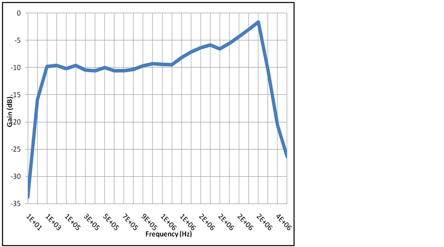
Figure 7. Pass Band Frequency response of NPDI.
isolation in the registration of a bioelectrical signal, in this case that of the heart (ECG). The electrical diagram is showed in Figure 9, where you can see all electronic components and the NPDI.
Now with the PCB designed electrical diagram of the same was done to build the circuit and physically testing directly with a test subject and observe his ECG signal on the oscilloscope. The PCB and the final circuit are shown in Figure 10.
The NPDI showed satisfactory results due to the signal response of ECG. In Figure 11 the cardiac monitor graphics can be observed the difference between input signal and output signal with minimal distortion due the sampled frequency of 16.2 KHz as shown in Figure 12.
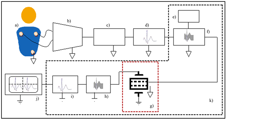
Figure 8. The block diagram to transmit a isolated ECG are: a) Function Generator (ECG signal) or patient, b) voltage follower from patient electrode leads and instrumentation amplifier INA128V with variable gain, c) DC suppressor, d) Impedance coupling circuit, e) function generator, f) voltage follower sample-and-hold circuit, g) NPDI, h) 60 Hz Band-reject filter, i) Passive half-wave circuit, j) Oscilloscope, k) isolation device.
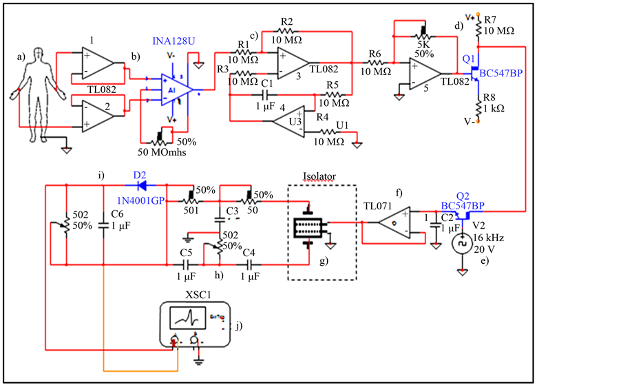
Figure 9. Electric Diagram of ECG isolator included the NPDI. a) subject of probe, b) voltage follower from subject electrode leads and instrumentation amplifier INA128V with variable gain, c) DC suppressor, d) Impedance coupling circuit, e) function generator for tuning, f) voltage follower sampleand-hold circuit, g) NPDI, h) 60 Hz Band-reject filter, i) Passive half-wave circuit, j) Oscilloscope.
5. Discussion
The NPDI device demonstrated a good performance as piezoelectric isolator due to its high electrical resistance and its pass band filter behavior. This device has didactic purposes because a study with several people implies a

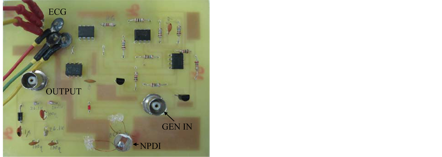
Figure 10. PCB of Electric Diagram of ECG isolator included the NPDI (CCP2) and ECG isolator circuit with NPDI.
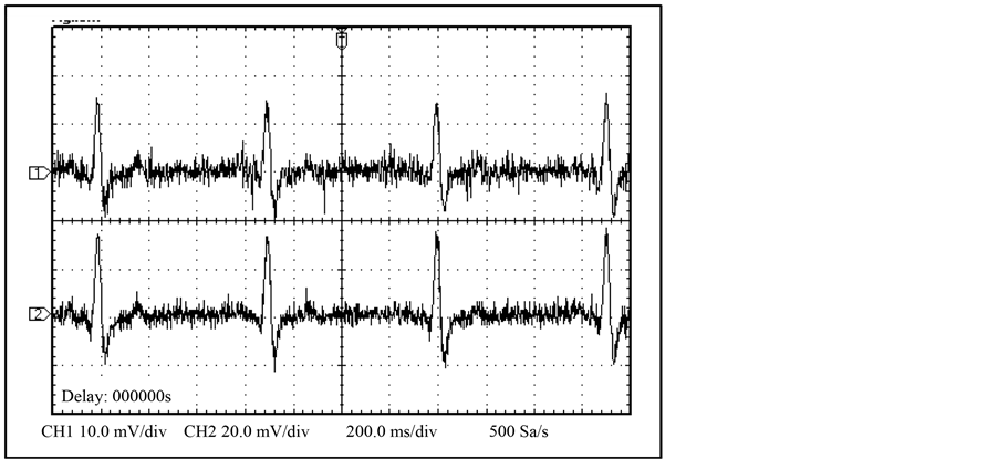
Figure 11. Human being input signal (1) and NPDI output signal (2).
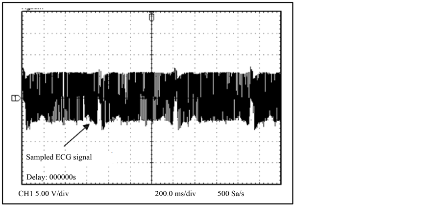
Figure 12. ECG signal sampled at 16.2 KHz.
research protocol. The legal steps in order to carry out these studies with patients of several ages are in preparation according to the recommendations of the declaration of Helsinki for investigation with human subjects (World Medical Association study) and The Bioethics Committee.
The NPDI has an interesting configuration because by the one hand it provides a great ceramic insulator that does not affect human beings and on the other hand it is very significant that this device was developed not only for this mechanical field of study, but also has multiple applications in different areas, for example: optics, acoustics, electrical and chemical sensing.
6. Conclusion
On the one hand, these results demonstrated that the NPDI is a good isolator and it has the following advantages: the increase in surface analysis is superior due to the Pt-wires, which works as a third and fourth electrodes; the proposed NPDI can be used at much higher temperatures than the conventional Si based sensors and do not need power supply; its frequency response is up to 2.2 MHz greater than any optoisolator; the NPDI is easy to make and the size of this bulk material can be modified; finally, the CCP offers good versatility as a mechanical, electrical, thermal and optical sensor due to its ferroelectricity [5] [8] [9] .
Acknowledgements
The National Council of The National Council of Science and Technology, Mexico (CONACYT) for supporting the project 151894. At Trieste-Italy, Latin American Network of Ferroelectric Materials (NET-43).
References
- Santos-Trigo, M., Suaste, E. and Figuerola, P. (2014) Technology and Tools Appropriation in Medical Practices. Encyclopedia of Information Science and Technology. 3rd Edition, IGI-Global, United Sates, in press.
- Haertling, G.H. and Land, C.E. (1971) Hot-Pressed (Pb, La)(Zr, Ti)O3 Ferroelectric Ceramics for Electrooptic Applications. Journal of the American Ceramic Society, 54, 1. http://dx.doi.org/10.1111/j.1151-2916.1970.tb12105.x-i1
- Suaste, E. and Flores, A. (2008) Behavior of the Temperature Dependence of Dielectric Constants and Curie Temperature Pt-Implanted Modified BaTiO3, KNbO3, PbZrO3,Pb0.88Ln0.08Ti0.98Mn0.02O3 (LN = La, Eu) Ceramics. Proc. XVII IMRC and VII Congress of NACE Int., Can-Cun, México, 17-20 August 2008 (S7-P1).
- Touloukian, Y.S., Powell, R.W., Ho, C.Y. and Klemens, P.G. (1970) Thermophysical Properties of Matter. Vol. 1. Thermal Conductivity: Metallic Elements and Alloys. IFI/Plenum Press, New York.
- Gonzalez-Moran, C.O. and Suaste-Gomez, E. (2009) Developed and Experimental Evidence of a Ceramic-Controlled Piezoelectric Bulk Implanted with Pt Wire Based on PLZT. Ferroelectrics, 392, 98-106. http://dx.doi.org/10.1080/00150190903412564
- Herbert, J.M. (1982) Ferroelectric Transducers and Sensors. Gordon and Breach, New York.
- Webster, J.G. (2014) Measurement, Instrumentation, and Sensors Handbook. 2nd Edition, CRC Press, Boca Raton.
- González-Morán, C.O., Flores-Cuautle, J.J.A. and Suaste-Gómez, E. (2010) A Piezoelectric Plethysmograph Sensor Based on a Pt Wire Implanted Lead Lanthanum Zirconate Titanate Bulk Ceramic. Sensors, 10, 7146-7156. http://dx.doi.org/10.3390/s100807146
- Suaste-Gómez, E., Flores-Cuautle, J.J.A. and González-Morán, C.O. (2010) Opacity Sensor Based on Photovoltaic Effect of Ferroelectric PLZT Ceramic with Pt Wire Implant. Sensors Journal, IEEE, 10, 1056-1060. http://dx.doi.org/10.1109/JSEN.2010.2042953
- Suaste Gómez, E., Flores Cuautle, J.J.A. and González Morán, C.O. (2011) Development of a Ceramic-Controlled Piezoelectric of Single Disc for Biomedical Applications. In: Laskovski, A.N., Ed., Biomedical Engineering, Trends in Materials Science, InTech, Rijeka, 87-100. http://dx.doi.org/10.5772/13072
- González-Morán, C.O., Cruz-Orea, A., Flores-Cuautle, J.J.A., Minor-Martínez, A. Elias-Viñas, D. and Suaste-Gómez, E. (2011) Ceramic-Controlled Piezoelectric Bulk Implanted with Pt Wire Based on BaTiO3 (Optocal Microscopy, SEM, EDS) and PLZT (Optical Bi-Dimensional Characterization). Ferroelectrics, 423, 111-115. http://dx.doi.org/10.1080/00150193.2011.620888
- IEC 60601-2-25 (1993-03) (1993) Medical Electrical Equipment—Part 2: Particular Requeriments for Safety of Electrocardiographs.
- Ganong, W.F. (2012) Review of Medical Physiology. McGraw-Hill, New York.
- Guyton and Hall (2011) Medical Physiology. Elseiver, Amsterdam.
- Khandpur, R.S. (2003) Handbook of Biomedical Instrumentation. McGraw-Hill, Tata.
- Geselowitz, D.B., et al. (1980) Electrical Safety Standards for Electrocardiographic Apparatus. Journal of the American Heart Association, 61, 669-670.
- Weinberg, D.I., Artley, J.L., Whalen, R.E. and McIntosh, H.D. (1962) Electric Shock Hazards in Cardiac Catheterization. Circulation Research, 11, 1004-1009. http://dx.doi.org/10.1161/01.RES.11.6.1004
- Whalen, R.E., Starmer, C.F. and Mclntosh, H.D. (1964) Electrical Hazards Associated with Cardiac Pacemaking. Annals of the New York Academy of Sciences, 111, 922-931. http://dx.doi.org/10.1111/j.1749-6632.1964.tb53162.x
- Roy, O.Z., Park, G.C. and Scott, J.R. (1976) Ventricular Fibrillation Thresholds versus Duration of Current Flow or the Number of 60 Hz Cycles. International Conference of the IEEE Engineering in Medicine and Biology, IEEE, New York, 394-395.
- Roy, O.Z., Scott, J.R. and Park, G.C. (1976) 60 Hz Ventricular Fibrillation and Pump Failure Thresholds versus Electrode Area. IEEE Transactions on Biomedical Engineering, BME-23, 45-48. http://dx.doi.org/10.1109/TBME.1976.324614
- Rao, C.R. and Guha, S.K. (2000) Principles of Medical Electronics and Biomedical Instrumentation. Universities Press, New Dheli.
- Yoneda, S. and Fukui, Y. (1980) A New Bilateral Optoisolator Circuit. IEEE Transactions on Components, Hybrids, and Manufacturing Technology, CHMT-3, 266-280.