Advances in Bioscience and Biotechnology
Vol.2 No.5(2011), Article ID:7837,6 pages DOI:10.4236/abb.2011.25056
Producing single microbubbles with controlled size using microfiber
![]()
1Department of Bioengineering and Robotics, Tohoku University, Sendai, Japan;
2Graduate School of Natural Science and Technology, Okayama University, Okayama, Japan.
E-mail: *deguchi@bml.mech.tohoku.ac.jp
Received 9 July 2011; revised 23 August 2011; accepted 31 August 2011.
Keywords: Microbubble; Nanobubble; Carbon Fiber; Glass Fiber; Infrared Laser; Drug Delivery System
ABSTRACT
Microbubble-mediated pore formation in sonoporation includes a combination of complex processes such as collision or coalescence of translating or collapsing microbubbles with vascular cells. Although understanding the pore formation mechanisms may improve drug delivery efficiency, their details are still poorly understood. In the present study, we describe an experimental model that produces single air bubbles with controllable size. A carbon microfiber in liquids is illuminated by an infrared laser to produce individual bubbles having size comparable to that of the microfiber. The microbubbles can be physically isolated from the fiber for placing at arbitrary positions in the liquids. The lifetime of the bubbles is several tens of minutes depending on the intensity of the laser used. The preparation of the controllable air bubbles may be useful in future investigations of ultrasound-mediated microbubble-cell interactions.
1. INTRODUCTION
Microbubbles are used in various industrial and medical fields such as pipe cleaning and drug delivery systems. Techniques for preparing microbubbles have been extensively studied [1-7]. Many of these studies focus on the efficiency of microbubble production in terms of the quantity of microbubbles that can be prepared at low cost. Most of these techniques produce microbubbles by mixing jet streams with air, and are therefore developed on the basis of fluid dynamic action. In other techniques, large quantities of microbubbles are generated by inducing vibrations of a material in a solution.
In the drug delivery systems, ultrasonic waves are applied from outside the blood vessels to stimulate bubbles containing medical drugs [8-16]. It is believed that the bursting of these bubbles followed by micro jet streams causes interactions with nearby cells and resultant local administration of drugs. For improving the transduction efficiency of medication by exposure to ultrasonic waves, it is important to accurately understand the physical mechanisms of the actual administration of the drugs in the vascular cells [17,18]. On the basis of the in vitro and/or ex vivo experiments, it may be beneficial to perform direct observation of bubble collapse and subsequent changes in the cell structure by using a highspeed camera. Only few such studies consider the mechanism of drug administration, and consequently clues for improving the administration efficiency may rely on researchers’ experience.
To investigate the effect of individual bubbles, it is advantageous to use a single bubble produced near target cultured cells, rather than using a bubble laboriously isolated from a pool of bubbles. In the present article, we report a simple technique to prepare single microbubbles in a solution. A single carbon fiber with a diameter of several microns was inserted in the liquids and illuminated by an infrared laser to produce an air bubble. This technique allows the preparation of single air microbubbles in arbitrary positions, and in future investigations, has the potential to reveal the effects of bubble burst on the cell structure.
2. MATERIALS AND METHODS
2.1. Experimental Setup
A carbon fiber (Nikkiso, Japan; Toray, Japan) with a diameter of 7 µm was fixed using an epoxy adhesive to the tip of a glass rod with a diameter of 1 mm (Narishige, Japan). The glass rod was then fixed to a water hydraulic micromanipulator (MHW-3, Narishige, Japan), thus allowing its position to be arbitrarily changed. The tip of the carbon fiber was inserted into distilled water or other solutions in a glass bottom cell culture dish with 35 mm diameter. The dish was placed on the stage of an inverted microscope (IX70, Olympus, Japan). The carbon fiber was illuminated by an infrared laser with a wavelength of 1064 nm (Sigma Koki, Japan) through an oil-immersion objective lens with a numerical aperture of 1.4 (working distance = 0.13 mm; UPlanSApo, Olympus, Japan). We examined the relationship between the laser intensity displayed on the device panel and that measured above the surface of the solution by using an optical power meter (ADCE8230E + 11, Advantest, Japan). Bright field images of the carbon fiber illuminated by a halogen lamp were acquired using a CCD camera (Sony, Japan). Experiments were performed at room temperature (23˚C).
2.2. Generation of Microbubbles
The carbon fiber tip was placed close to the focal point of the laser by using the micromanipulator. Microbubbles were generated at the illuminated point on the carbon fiber. In addition to the combination of distilled water and carbon fiber, we performed this experiment by using a wide variety of liquids and micro-sized fibers, and examined the generation of microbubbles. We also investigated the effect of varying both laser intensity and laser exposure time. After microbubbles appeared, we isolated them from the fiber and observed their behavior. Image analyses were performed to examine changes in the bubble’s diameter with time. To examine changes in the carbon fiber structure before and after laser illumination, the surface of the carbon fibers was observed by scanning electron microscopy (Real Surface View, Keyence, Japan). In this observation, individual carbon fibers were illuminated in distilled water for 5 min by the laser with 0.3 W intensity displayed on the device panel. In a separate experiment, to demonstrate that the present technique allows arbitrary positioning of individual bubbles, a bubble generated on the fiber surface was moved close to bovine aortic endothelial cells cultured on a dish (containing Dulbecco’s modified Eagle medium supplemented with 10% fetal bovine serum).
3. RESULTS
The relationship between the laser intensity that displayed on the device panel and that measured above the dish was examined (Figure 1). A linear regression line was obtained from the average data. The laser intensity was controlled on the basis of this calibration data measured prior to the experiments. Unless otherwise stated, hereafter, the intensity value represents that measured above the dish. Multiple microbubbles were generated at the surface of the carbon fiber when it was placed within the focal point of the microscope (Figure 2(a)). On exposing the fiber to a low intensity laser, single bubbles were successfully produced (Figure 2(b)). The size of

Figure 1. Calibration of laser intensity. The x-axis represents the laser intensity displayed on the device panel and controlled by the users. The y-axis represents the laser intensity measured above the dish. Data (mean ± SD) are from four independent measurements with a linear regression of the average data.
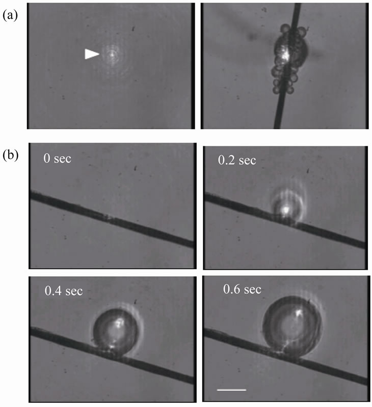
Figure 2. Laser-induced generation of microbubbles. (a) Multiple bubbles are generated when the fiber was placed in the focal point of the illuminated laser (arrowhead). (b) Sequential images of single microbubble generation. Scale bar, 20 µm.
the bubbles could be arbitrarily changed by controlling the laser exposure time and/or laser intensity. When the fiber was displaced from the focal point in the z-direction, we did not observe microbubble production even with long exposure time of several minutes to laser illumination. In contrast, when both the fiber and the focal point were displaced in the z-direction, bubbles were produced although high laser intensity was required as the distance between the fiber and the bottom surface of the dish increased (Figure 3). Two types of carbon fibers from different companies (Nikkiso and Toray) showed similar behavioral patterns (compared data not shown).
Laser intensity measurements using the optical power meter showed that the minimum intensity required for microbubble generation in distilled water was 0.11 mW (Figure 3). We confirmed that microbubbles were generated using the carbon fiber in other solutions instead of distilled water such as corn oil (Nisshin, Japan) (Figure 4(a)). The minimum intensity necessary for bubble generation in corn oil was 0.09 mW, and it increased as the distance between the fiber and the bottom surface of the dish was increased (Figure 3). To further compare the efficiency in microbubble generation, we prepared a thin glass needle with a tip width of ~20 µm as a substitute for the carbon fiber. This glass needle was manufactured from a 1 mm diameter glass rod (used as a base for fixing the carbon fiber in the experiments of Figure 2) by heating and pulling a melted part using weight. A microfiber made of glass reinforced cement (GRC) was also tested. Laser intensities of 2.0 and 0.25 mW were necessary for the glass fiber and the GRC fiber (Figures 4(b) and (c)), respectively, to produce a laser illuminationinduced microbubble.
Microbubbles could be isolated from the fiber surface by rubbing an individual bubble against the bottom surface of the dish by using the three-dimensional manipulator (Figure 5). We observed single microbubbles placed on the dish that were independent of the fibers under the microscope to characterize the shrinking properties. To evaluate the effect of the laser intensity, single bubbles with a diameter of 70 µm were produced and isolated from the carbon fibers. The diameter of the bub-

Figure 3. High laser intensity is required for bubble generation in both distilled water and corn oil as the distance between the carbon fiber and dish bottom surface is increased.

Figure 4. Images of before and after bubble generation under different conditions. (a) Carbon fiber in corn oil. (b) Glass fiber in distilled water. (c) GRC fiber in distilled water. Scale bar, 20 µm.

Figure 5. Shrinkage of bubbles over time. Images show excerpts from data for 0.14 and 1.00 mW (measured on the surface of the dish). The diameter of the carbon fiber is approximately 7 µm.
bles gradually decreased over a time scale dependent on the laser intensity (Figure 5). A bubble produced by 0.14 mW took 500 s to disappear, while that by 1.00 mW took 2200 s.
The surface of the carbon fibers used (n = 6) was examined by scanning electron microscopy before and after the laser illumination in distilled water (Figure 6). The microstructure of all the carbon fibers observed were apparently kept intact except that unidentified materials were adhered to the surface of the carbon fibers observed after the laser illumination.
To more clearly demonstrate that the present technique enables arbitrary positioning of individual bubbles, a bubble was generated using a carbon fiber in cell culture media (Figure 7). The bubble was moved just above an endothelial cell; this allows future investigations of the interactions between bubbles and cells.
4. DISCUSSION
We demonstrated the laser illumination-induced generation of single microbubbles with an arbitrary size. High optical energy within the laser focal point allows concentrated heat generation in the illuminated fiber and the subsequent generation of air bubbles. The diameter of the generated bubbles is determined by the fiber width (i.e., <10 µm in this case). Therefore, we can obtain single microbubbles whose sizes are dependent on the illuminated material. Thus, it might be possible to produce nanobubbles (or more precisely, submicrobubbles) if we use a nanometer-sized carbon fiber or carbon nanotubes.
Another advantage of this technique is the ability to produce individual bubbles at an arbitrary position by manipulating the fiber position (Figure 7); such manipulation is easily performed using the commercially available micromanipulator. In contrast, while conventional techniques based on fluid dynamic action or ultrasound vibrations may be suitable for generating large quantities of bubbles [1-7], it is generally difficult to produce an individual bubble using these techniques. Actual controlled-release drug delivery systems use functionalized micro or nanobubbles containing drugs that are different from the air cavities obtained in the present study [8-16]. However, it is reasonable to assume that the mechanisms of bubble burst-induced pore formation in the cell membranes [17,18] (from which drugs could be introduced) are similar for the actual functionalized bubbles and the air bubbles obtained in this study. The single controllable bubbles that we obtained may therefore be useful for future direct observation of the effects of bubble burst on structural changes of cultured cells to investigate the basic mechanisms of drug delivery.
It is likely that a local increase in temperature at the fiber-liquid interface due to laser illumination contributed to the generation of microbubbles. Higher energy of the laser was required as the distance between the fiber and dish increased while the position of the focal point was lifted together with the fiber position (Figure
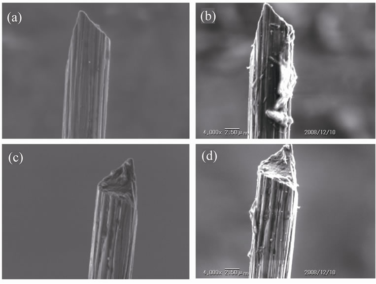
Figure 6. A typical example of scanning electron microscopy images. A carbon fiber before (a) and after (b) the laser illumination is shown. The same carbon fiber viewed from a different angle is shown before (c) and after (d) the laser illumination.
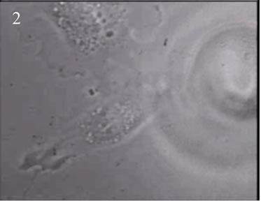


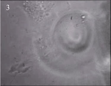
Figure 7. Positioning of an individual bubble on a cultured cell. A bubble (arrow) was initially generated on a carbon fiber and placed close to a target cell (outlined in blue) by manipulating the fiber (1-3). The bubble (outlined in red) was finally placed above the cell (4). Scale bar, 20 µm.
3). We speculate that the energy loss is partly caused by absorption of the infrared laser light in water along the increased light path from the dish surface to the fiber. In separate experiments, bubble generation was observed in combinations other than those of carbon fiber and distilled water (Figure 4). The carbon fibers have a high heat absorption capacity compared to glass, which allows the efficient transfer of light energy to heat, leading to temperature increase. The bubble generation efficiency would change depending on the materials used; therefore, more detailed investigations are imperative to determine more efficient conditions.
In future articles, we will report the effects of degassing to distinguish between liquid boiling and the expansion of a microscopic air bubble present in the liquid, both of which may be responsible for the bubble generation. Alternatively, microscopic bubbles that originally adhered to the fiber surface may expand, resulting in the appearance of microbubbles. However, microbubbles were generated even after long heating time of several hours using the same carbon fibers, suggesting that it is unlikely that microscopic bubbles remaining on the surface of the solid body are responsible for the appearance of the macroscopic bubbles. For some conditions, we observed that microbubbles remained on the bottom of the dish and had a long lifetime, in some cases as long as several tens of minutes (Figure 5). If the bubbles were made of water vapor, the cooling effect of the surrounding water would cause their return to the liquid after a short period of time. Thus, the lifetime of the bubbles is another issue that needs to be completely elucidated.
Here, we formulate influencing factors that lead to temperature increase. From the first law of thermodynamics at constant volume,
 (1)
(1)
where dq, du, Cv, and dt are the amount of energy added to the system by the heating process, the change in the internal energy of the system, the specific heat capacity at constant volume, and the change in temperature, respectively. When integration of Equation (1) is carried out from state 1 (prior to activating the laser beam) to state 2 (after activating the laser beam), the following equation is obtained
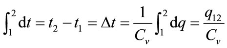 . (2)
. (2)
Here, integration constant q12 can be represented by
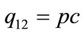 (3)
(3)
because the input energy (q12) is derived from the infrared laser power (p) as well as the extent to which the fibers suspended in the liquids absorb the laser light as heat (c). As a consequence, laser illumination-induced temperature increase ( ) is represented by
 . (4)
. (4)
Equation (4) indicates that heat-induced bubble generation tends to occur when the solid object fibers have low specific heat at constant volume and high thermal absorption as well as when a powerful laser is used for illumination. Among solid materials, carbon fibers/tubes appear to be suitable because they fulfill these requirements. The use of an infrared laser is also suitable for the present purpose considering the high water absorption ability.
Taylor and colleagues [19-21] reported that microbubbles were generated at the output end of an optical fiber with a laser power of 10 - 30 mW. The fiber end at which bubbles adhered had a specially designed and etched conical tip with a hollow reservoir. We speculate that these microbubbles are generated by a mechanism that is identical to that used in this study, i.e., laserinduced increase in temperature followed by water boiling and/or expansion of a microscopic air bubble originally present in the liquid. However, the present study demonstrated that similar bubbles could be generated at an arbitrary position (where the laser is illuminated) by using more widely available materials such as crude carbon fibers and glass fibers.
Microbubble generation was not observed in areas outside the laser focal point even along the length of the carbon fiber. In addition, microbubbles were not generated at laser intensity below the threshold (i.e., ~0.1 mW measured above the dish) even when the fibers were exposed to laser illumination for a long period of time. These results suggest that locally accumulated heat remains in the fiber for only a short time. Rapid thermal dissipation, although not considered in the aforementioned formulation, may be due to the fact that the fiber is small in size, thus allowing prompt heat transfer to the surrounding environment.
In addition to the possible contribution to the field of medical engineering by improving drug delivery systems, the present technique may be applicable to other fields such as for use in inkjet printers. Conventional thermal methods eject controlled amounts of ink by using an air bubble that is produced via heating a thermal conductive material by applying electric current. In this method, the entire body of the thermal conductive materials is heated, thus rendering it incapable of controlling the position from which bubbles are generated. In contrast, the present technique enables localized bubble generation using laser illumination, thereby enabling controlled amounts of microbubbles to be generated at any arbitrary position. The bubble generation results in apparently no damage to the microfiber (Figure 6). The unidentified materials that adhere to the fiber surface after laser illumination are probably dust present in the liquids. Such contamination would be removed in a clean environment allowing repeatable use of the fiber. The use of localized laser illumination may thus lead to development of smaller and more accurate ink jet nozzles.
5. ACKNOWLEDGEMENTS
The authors thank Yoshihiko Tamura for his assistance in manufacturing the apparatus and Seiichi Washio for helpful discussions. SD gratefully acknowledges the support from the Japan Science and Technology Agency. This work was partly supported by Grants-in-Aid for Scientific Research from the Japan Ministry of Education, Culture, Sports, Science, and Technology (#21680039 and #20001007).
REFERENCES
- Yamano, I. and Tamagawa, M. (2006) Deformation analysis of bubble near curved elastic wall for developing shock wave DDS. JSME International Journal Series B, 49, 755-760. doi:10.1299/jsmeb.49.755
- Shirota, T., Sanada, T., Arata, Y., Watanabe, M. and Kameda, M. (2007) Formation of single bubble of sub-millimeter size using pulsed pressure fluctuation of gas. Japan Society of Mechanical Engineers B, 73, 467- 473. doi:10.1299/kikaib.73.467
- Shintaku, H., Imamura, S. and Kawano, S. (2008) Microbubble formations in MEMS-fabricated rectangular channels: A high-speed observation. Experimental Thermal and Fluid Science, 32, 1132-1140. doi:10.1016/j.expthermflusci.2008.01.004
- Shirota, M., Imamura, T. and Kameda, M. (2008) Formation of single bubbles from a submerged orifice using pulsed ultrasound waves. Journal of Fluid Science and Technology, 3, 183-194. doi:10.1299/jfst.3.183
- Washio, S., Takahashi, S., Murakami K., Tada, T. and Deguchi, S. (2008) Cavity generation by accelerated relative motions between solid walls contacting in liquid. Journal of Mechanical Engineering Science, 222, 1695- 1706.
- Sanada, T., Sato, A., Shirota, M. and Watanabe, M. (2009) Motion and coalescence of a pair of bubbles rising side by side. Chemical Engineering Science, 64, 2659-2671. doi:10.1016/j.ces.2009.02.042
- Terasaka, K., Sasada, Y., Kobayashi, D. and Fujioka, S. (2011) Submilli-bubble dispersion from a slit orifice into water. Journal of Chemical Engineering of Japan, 44 140-145. doi:10.1252/jcej.10we185
- Kodama, T., Tomita, Y., Koshiyama, K. and Blomley, M.J.K. (2006) Transfection effect of microbubbles on cells in superposed ultrasound waves and behavior of cavitation bubble. Ultrasound in Medicine and Biology, 32, 905-914. doi:10.1016/j.ultrasmedbio.2006.03.004
- Koshiyama, K., Kodama, K., Yano, T. and Fujikawa, S. (2006) Structural change of lipid bilayer and water penetration induced by shock wave: Molecular dynamics simulations. Biophysical Journal, 91, 2198-2205. doi:10.1529/biophysj.105.077677
- Schlicher, R.K., Radhakrishna, H., Tolentino, T.P., Apkarian, R.P., Zarnitsyn, V. and Prausnitz, M.R. (2006) Mechanism of intracellular delivery by acoustic cavitation. Ultrasound in Medicine and Biology, 32, 915-924. doi:10.1016/j.ultrasmedbio.2006.02.1416
- Hallow, D.M., Mahajan, A.D. and Prausnitz, M.R. (2007) Ultrasonically targeted delivery into endothelial and smooth muscle cells in ex vivo arteries. Journal of Controlled Release, 118, 285-293. doi:10.1016/j.jconrel.2006.12.029
- Koshiyama, K., Kodama, K., Yano, T. and Fujikawa, S. (2008) Molecular dynamics simulation of structural changes of lipid bilayers induced by shock waves: Effects of incident angles. Biochimica et Biophysica Acta, 1778, 1423-1428. doi:10.1016/j.bbamem.2008.03.010
- Kodama, T., Tomita, Y., Watanabe, Y., Koshiyama, K., Yano, T. and Fujikawa, S. (2009) Cavitation bubbles mediated molecular delivery during sonoporation. Journal of Biomechanical Science and Engineering, 4, 124- 140. doi:10.1299/jbse.4.124
- Kumon, R.E., Aehle, M., Sabens, D., Parikh, P., Han, Y.W., Kourennyi, D. and Deng, C.X. (2009) Spatiotemporal effects of sonoporation measured by real-time calcium imaging. Ultrasound in Medicine and Biology, 35, 494- 506. doi:10.1016/j.ultrasmedbio.2008.09.003
- Koshiyama, K., Yano, T. and Kodama, T. (2010) Selforganization of a stable pore structure in a phospholipid bilayer. Physical Review Letters, 105, 018105. doi:10.1103/PhysRevLett.105.018105
- Koshiyama, K. and Wada, S. (2011) Molecular dynamics simulations of pore formation dynamics during the rupture process of a phospholipid bilayer caused by highspeed equibiaxial stretching. Journal of Biomechanics, 44, 2053-2058. doi:10.1016/j.jbiomech.2011.05.014
- Van Wamel, A., Bouakaz, A., Versluis, M. and De Jong, N. (2004) Micromanipulation of endothelial cells: Ultrasound-microbubble-cell interaction. Ultrasound in Medicine and Biology, 30, 1255-1258. doi:10.1016/j.ultrasmedbio.2004.07.015
- Van Wamel, A., Kooiman, K., Harteveld, M., Emmer, M., Ten Cate, F.J., Versluis, M. and De Jong, N. (2006) Vibrating microbubbles poking individual cells: Drug transfer into cells via sonoporation. Journal of Controlled Release, 112, 149-155. doi:10.1016/j.jconrel.2006.02.007
- Taylor, R.S. and Hnatovsky, C. (2004) Trapping and mixing of particles in water using a microbubble attached to an NSOM fiber probe. Optics Express, 12, 916-928. doi:10.1364/OPEX.12.000916
- Taylor, R.S. and Hnatovsky, C. (2004) Growth and decay dynamics of a stable microbubble produced at the end of a near-field scanning optical microscopy fiber probe. Journal of Applied Physics, 95, 8444-8449. doi:10.1063/1.1751631
- Diop, M. and Taylor, R. (2006) Soft trapping and manipulation of cells using a disposable nanoliter biochamber. Biophysical Journal, 90, 3813-3822. doi:10.1529/biophysj.105.075614