Agricultural Sciences
Vol.3 No.4(2012), Article ID:20042,7 pages DOI:10.4236/as.2012.34063
Effect of drip irrigation circuits design and lateral line length on: II-flow velocity and velocity head
![]()
1WRFI Department, National Research Center (NRC), Giza, Egypt; *Corresponding Author: tayelmynrc@yahoo.com
2Southern Illinois University Carbondale, Carbondale, USA
Received 7 January 2012; revised 13 February 2012; accepted 11 March 2012
Keywords: Drip; Irrigation; Circuit; Laterals; Flow; Head; Velocity
ABSTRACT
The objectives of the work were to study the effect of drip irrigation circuits (DIC) and lateral lines lengths (LLL) on: Flow velocity (FV) and velocity head (VH). Laboratory tests were conducted at Irrigation Devices and Equipments Tests Laboratory, Agricultural Engineering Research Institute, Agriculture Research Center, Giza, Egypt. The experimental design of laboratory experiments was split in randomized complete block design with three replicates. Laboratory tests carried out on three irrigation lateral lines 40, 60, 80 m (LLL1, LLL2; LLL3) under the following three drip irrigation circuits (DIC): a) one manifold for lateral lines or closed circuits with one manifold of drip irrigation system (CM1DIS); b) closed circuits with two manifolds for lateral lines (CM2DIS), and c) traditional drip irrigation system (TDIS) as a control. Concerning FV values, DIC and LLL treatments could state in the following ascending orders: TDIS < CM1DIS < CM2DIS and LLL1 < LLL2 < LLL3, respectively. FV varied from 0.593 m·sec–1 to 1.376 m·sec–1. i.e. FV < 5 ft·sec–1 and this is necessary to avoid the effect of water hammer in the main and sub-main lines, but in lateral line, it can cause silt and clay precipitation problems. The differences in FV among DIC and LLL were significant at the 1% level. The effect of interaction: DIC X LLL on FV values, were significant at the 1% level. The maximum and minimum values of FV were noticed in these interactions: CM2DIS X LLL3 and TDIS X LLL1, respectively. The following ascending orders TDIS < CM1DIS < CM2DIS and LLL1 < LLL2 < LLL3 expressed their effects on VH respectively. Differences in VH among DIC and/or LLL were significant at the 1% with few exceptions. The effects of interactions: DIC X LLL on VH were significant at the 1% level in some cases. The maximum and minimum values of VH were found in the interactions: CM2DIS X LLL3 and TDIS X LLL1, respectively.
1. INTRODUCTION
Drip irrigation, as cutting edge technology in irrigation methods has many advantages but it is associated with some problems and obstacles i.e. low water pressure at the end of lateral lines and salt accumulation. On the other hand, drip irrigation systems require adequate hydraulic design, ensuring the averaged flow velocity of discharge and velocity head along lateral line length.
[1,2] apply energy-gradient line approach considering constant dripper discharge along the lateral for determining the lateral pressure head and the discharge rate profiles. [3,4] have developed an equation based on the differential equation of conservation of energy and the continuity equation. The Darcy-Weisbach equation for head loss due to friction loss is used as an accurate formula for a small diameter smooth pipes. The friction loss coefficient is reported for different ranges of Reynold numbers variation (from laminar to fully turbulent discharge conditions). The velocity head is neglected, but the variable discharge is included in the basic derivation. [5,6] have presented an equation applying the energy equation for two successive drippers. The friction coefficient is also reported for different ranges of the Reynolds number variation. The Darcy-Weisbach equation for head loss due to friction loss is used. The change of pressure head due to a momentum change at the dripper is reported.
[7-9] have developed an equations of designing single as well as pared laterals, based on the equation of conservation of energy. The change of dripper discharge along the lateral line length is approximated by a polynomial to the power of n (n = 3/7). The coefficients of the polynomial are determined using the least square method at a given inlet discharge rate of lateral and at an inlet pressure head of lateral line. The Darcy-Weisbach equation for head loss due to friction loss was used too. The friction loss coefficient was considered as a function of Reynolds number for different discharge conditions (from laminar to fully turbulent).
[10] have developed an equation of designing horizontal, non-deformable drip lateral line on the basis of the momentum approach. The longitudinal projection of discharged velocity was considered as a linear function of the averaged discharge velocity. An analytical decision of the two differential equations obtained was proposed (the momentum equation and the conservation of mass equation) [11].
[12,13] have performed a good comparative analysis of the developed hydraulic methods in design of microirrigation laterals.
[14-16] took into account the influence of temperature on the viscosity change in the hydraulic design of drip irrigation system. It was proved that when the water temperature changes from 15.5˚C to 37.7˚C (from 60˚F to 100˚F) the density decreases by less than 1% but viscosity decreases by about 40% [17]. That is why the influence of temperature and Reynolds number will be taken into account when the change of water kinematic viscosity is considered.
The aim of the work presented in this paper is studying the effect of drip irrigation circuits (DIC) used: 1) Closed irrigation circuit with one manifold for lateral lines (CM1DIS), 2) Closed irrigation circuit with two manifolds for lateral lines (CM2DIS), 3) traditional drip irrigation system (TDIS) as a control and lateral lines lengths (LLL): (LLL1 = 40 m, LLL2 = 60 m, LLL3 = 80 m) on Flow velocity (FV) and velocity head (VH).
2. MATERIAL AND METHODS
The laboratory tests were conducted at Irrigation Devices and Equipments Tests Laboratory, Agricultural Engineering Research Institute, Agricultural Research Center, Giza, Egypt. The experimental design of laboratory experiments was split in randomized complete block design with three replicates. Laboratory tests carried out on three irrigation lateral lines 40, 60, 80 m under the following three drip irrigation circuits (DIC) of: 1) one manifold for lateral lines or closed circuits with one manifold of drip irrigation system (CM1DIS); 2) closed circuits with two manifolds for lateral lines (CM2DIS), and 3) traditional drip irrigation system (TDIS) as a controll, Figures 1-3. Figure 4 showed the directions of flow inside manifold and lateral tubes in the different DIC tested. Details of the pressure and water supply control have been described by [18]. Test has been carried out in order to resolve the problem of lack of pressure head at the end of lateral lines in the TDIS.
Irrigation networks include the following components as shown in Figures 1-3: 1. Control head: It was located at the water source supply. It consists of centrifugal pump 3”/3”, driven by electric engine (pump discharge of 80 m3·h–1 and 40 m lift), sand media filter 48” (two tanks), screen filter 2” (120 mesh), back flow prevention device, pressure regulator, pressure gauges, flow-meter, control valves and chemical injection, 2. Main line:
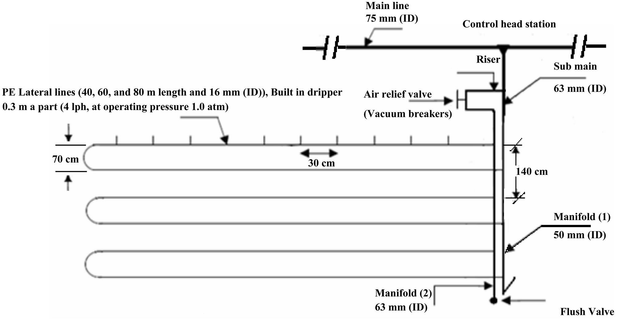
Figure 1. Layout of drip closed circuit with two manifolds (CM2DIS) for lateral lines.
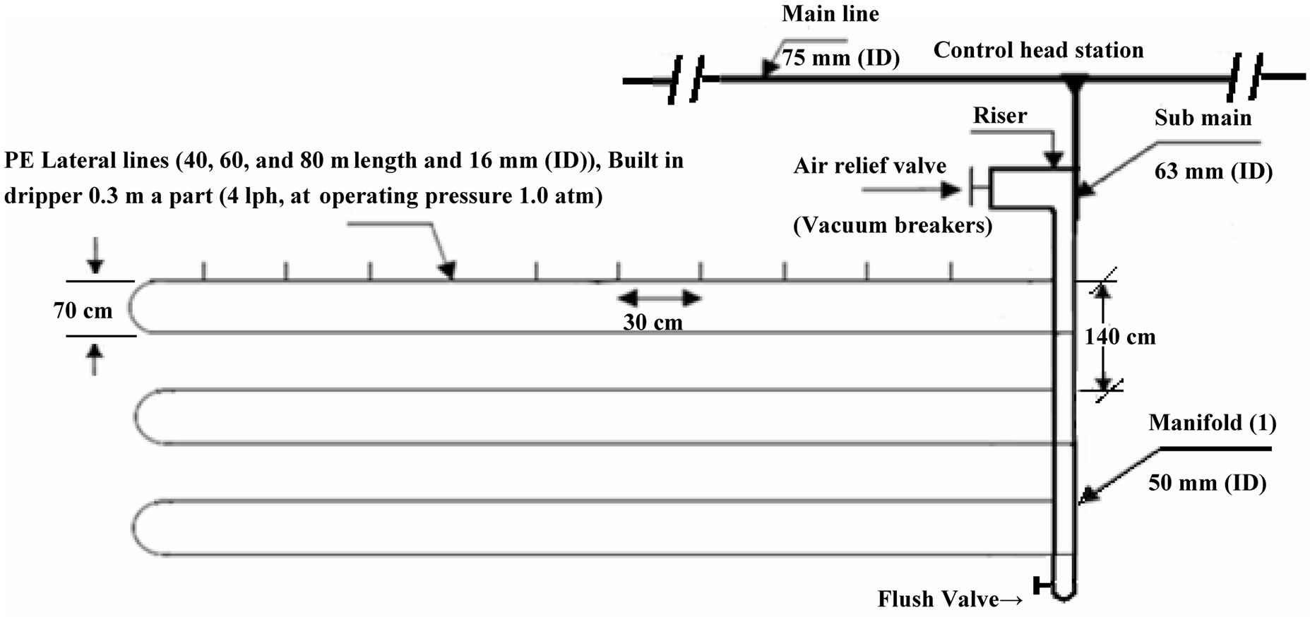
Figure 2. Layout of drip closed circuits with one manifold (CM1DIS) for lateral lines.
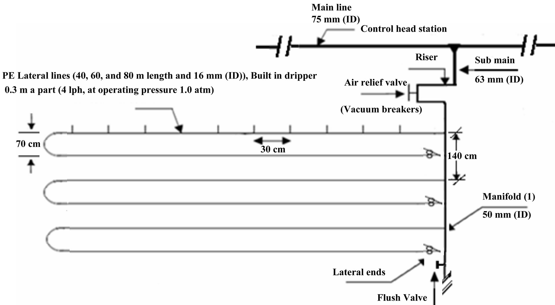
Figure 3. Layout of traditional drip irrigation system (TDIS).
PVC pipes of 75 mm in ID to convey the water from the source to the main control points in the field, 3. Submain lines: PVC pipes of 75 mm in ID were connected to the main line through a control unit consists of a 2” ball valve and pressure gauges, 4. Manifold lines: PVC pipes of 50 mm in ID were connected to the sub main line through control valves 1.5”, 6. Lateral lines: PE tubes of 16 mm in ID were connected to the manifolds through beginnings stalled on manifolds lines, 7. Emitters: These emitters (GR) built in PE tubes 16 mm in ID, emitter discharge of 4 l·h–1 at 1 atm. Nominal operating pressure and 30 cm spacing in-between. The components of closed circuits of the drip system include, supply lines, control valves, supply and return manifolds, drip lateral lines, emitters, check valves and air relief valves/vacuum breakers [19].
The flow rate through the pipe depends on pipe surface roughness and air layer resistance. The change of hydraulic friction coefficient values, depending on variations in Re number values. Hydraulic losses at plastic pipes might be calculated as losses at hydraulically smooth pipes, multiplied by correction coefficients that assess
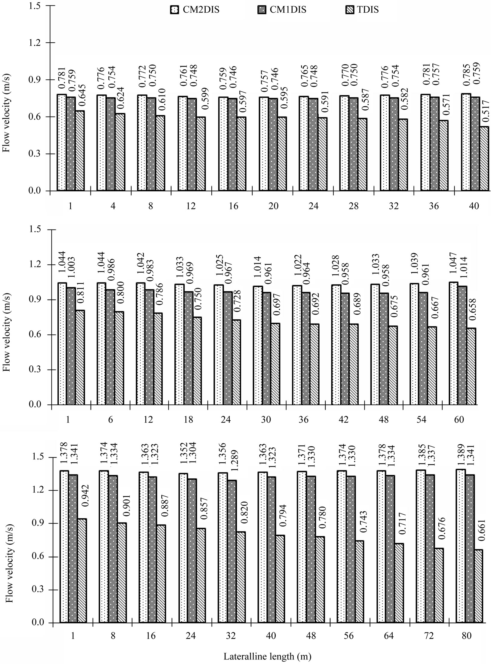
Figure 4. Effect of different irrigation circuits designs on flow velocity along different lateral line lengths under (operating pressure 1.0 atm and slope = 0%).
losses at pipe joints and air resistance.
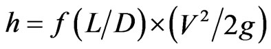
[20] stated that head loss due to friction was calculated using the following Darcy-Weisbach equation:
 (1)
(1)
where h = head loss, m; f = friction factor; L = length of pipe, m; D = ID Ø of pipe work, m; v = velocity of fluid, m/s; g = acceleration due to gravity, m·sec–2.
Friction factor can be expressed as:
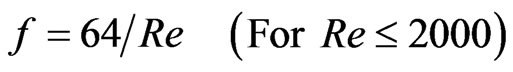 (2)
(2)
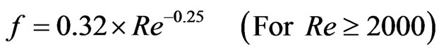 (3)
(3)
where Re = Reynolds’ number, which can be expressed as:
 (4)
(4)
where v = fluid velocity, m/sec; D = ID Ø of lateral, m; and µ = kinematic viscosity of water = 1 × 10⁻⁶ m2·sec–1, at 20˚C.
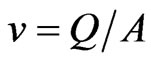
Velocity v (m/s) can be expressed as:
 (5)
(5)
where, Q = lateral flow rate (m3·sec–1) (average flow rate per emitter x number of emitters), and A = cross sectional area of lateral (m2).
MSTATC program (Michigan State University) was used to carry out statistical analysis. Treatments mean were compared using the technique of analysis of variance (ANOVA) and the least significant difference (L.S. D) between systems at 1% [21].
3. RESULTS AND DISCUSSION
Table 1 and Figure 4 indicated the effect of DIC and LLL on FV. The reader can deduce that the change in FV took the same trend of PH, whereas, it was opposite to that of friction loss. The explanation for this could be due to the effect of both DIC on both PH and friction loss. Also, increasing LLL increased its discharge and decreased the amount of water flowing along the lateral lines while, their cross section areas are constant are other reasons.
According to the FV values, the DIC used could be put in the following ascending order: TDIS < CM1DIS < CM2DIS. Difference in FV between any two DIC was significant at the 1% level. FV varied from 0.593 m·sec–1 to 1.376 m·sec–1. i.e. FV < 5 ft·sec–1 and this is necessary to a avoid the effect of water hammer in the main and sub-main lines, but in lateral line, it can cause silt and clay precipitation problems.
Concerning the effect of LLL on FV, it is obvious that the FV of LLL3 exceed that of LLL1, while that of LLL2 occupied and intermediate position in between. Differences in FV among LLL treatments were significant at the 1% level. The effects of the DIC X LLL on FV were significant at 1% level. The maximum and minimum flow velocities were achieved in the interactions of: CM2DIS X LLL3 and TDIS X LLL1, respectively.
Since velocity head is calculated from the following equation:
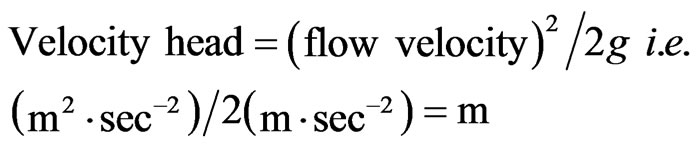
It took the same trend of flow velocity.
According to Table 1 and Figure 5; VH values, DIC could be stated in the following ascending order: TDIS < CM1DIS < CM2DIS. Differences in VH among DIC were significant at the 1% level except that between
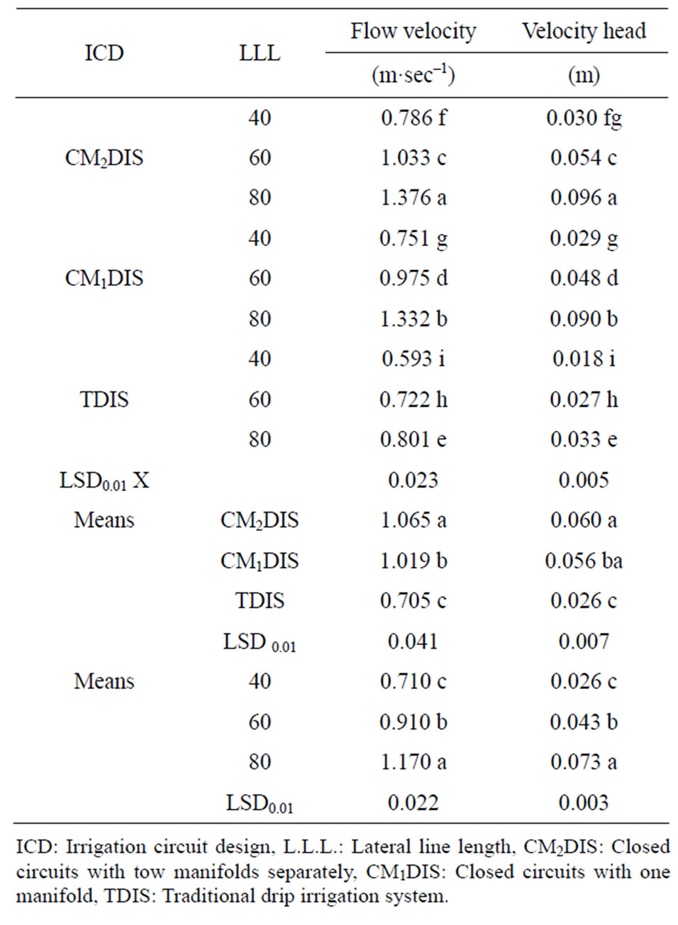
Table 1. Effect of (DIC) and LLL on Flow velocity and velocity head (operating pressure = 1 atm and slope = 0%).
CM2DIS and CM1DIS.
Concerning the effect of LLL on VH, they can be written in the follow ascending order: LLL1 < LLL2 < LLL3. Differences in VH among LLL treatments were significant at the 1% level without exceptions.
The effects of the DIC X LLL on VH were significant at the 1% level except some cases i.e. CM2DIS X LLL2, CM1DIS X LLL1 and TDIS X LLL3.
The maximum and minimum values of VH were found in the following interactions: CM2DIS X LLL3 and TDIS X LLL1, respectively.
4. SUMMARY AND CONCLUSIONS
Drip irrigation systems, as cutting edge technology in irrigation methods has many advantages but it is associated with some problems and obstacles i.e. low water pressure at the end of lateral lines and salt accumulation. Closed-circuits were proposed as incorporating modification to the traditional drip irrigation system. The aims of the work were to study the effect of drip irrigation circuits (DIC) used: 1) Closed irrigation circuit with one manifold for lateral lines (CM1DIS); 2) Closed irrigation circuit with two manifolds for lateral lines (CM2DIS), 3) traditional drip irrigation system (TDIS) as a control and
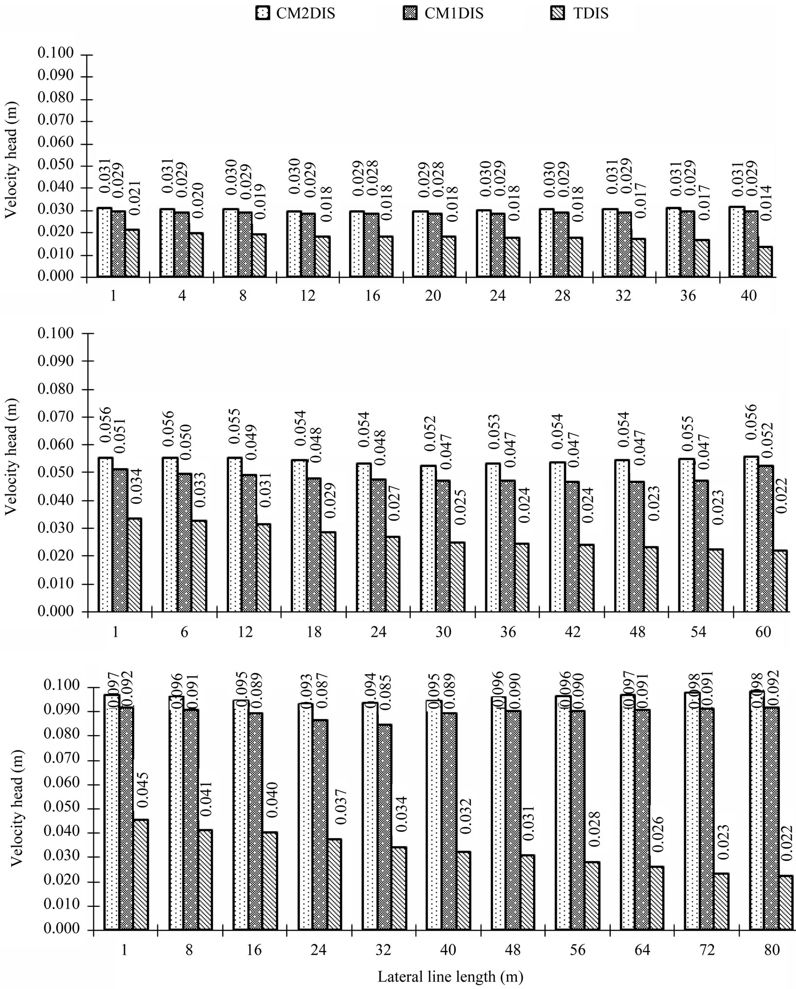
Figure 5. Effect of different closed circuits designs on velocity head along different lateral line lengths under (operating pressure 1.0 atm and slope = 0%).
lateral lines lengths (LLL): (LLL1 = 40 m, LLL2 = 60 m, LLL3 = 80 m) on: flow velocity and velocity head.
To achieve aims mentioned. The laboratory experiments were conducted at irrigation Devices and Equipments Tests Laboratory, Agriculture Engineering Research Institute, Agriculture Research Center, Ministry of Agricultural and Land Reclamation, Egypt.
Concerning FV values, DIC and LLL treatments could stated in the following ascending orders: TDIS < CM1DIS < CM2DIS and LLL1 < LLL2 < LLL3, respectively. The differences in FV among DIC and LLL were significant at the 1% level.
The effect of interaction: DIC X LLL on FV values, were significant at the 1% level. The maximum and minimum values of FV were noticed in these interactions: CM2DIS X LLL3 and TDIS X LLL1, respectively.
The following ascending orders TDIS < CM1DIS < CM2DIS and LLL1 < LLL2 < LLL3 expressed their effects on VH respectively. Differences in VH among DIC and/or LLL were significant at the 1% with few exceptions.
The effects of interactions: DIC X LLL on VH were significant at the 1% level in some cases. The maximum and minimum values of VH were found in the interactions: CM2DIS X LLL3 and TDIS X LLL1, respectively.
REFERENCES
- Wu, I.P. and Gitlin, H.M. (1975) Energy gradient line for drip irrigation laterals. Journal of the Irrigation and Drainage Division, 101, 323-326.
- Wu, I. and Yue, R. (1993) Drip lateral design using energy gradient line approach. Transactions of the ASAE, 36, 389-394.
- Warrick, A. and Yitayew, M. (1988) Trickle lateral hydraulics. I: Analytical solution. Journal of Irrigation and Drainage Engineering, 114, 281-288. doi:10.1061/(ASCE)0733-9437(1988)114:2(281)
- Yitayew, M. and Warrick, A. (1988) Trickle lateral hydraulics. II: Design and examples. Journal of Irrigation and Drainage Engineering, 114, 289-300. doi:10.1061/(ASCE)0733-9437(1988)114:2(289)
- Hathoot, H., Al-Amoud, A. and Mohammad, F. (1993) Analysis and design of trickle-irrigated laterals. Journal of Irrigation and Drainage Engineering, 119, 756-767. doi:10.1061/(ASCE)0733-9437(1993)119:5(756)
- Hathoot, H., Al-Amoud, A. and Al-Mesned, A. (2000) Design of trickle irrigation lateral as considering emitter losses. Journal of the International Commission on Irrigation and Drainage, 49, 1-14.
- Kang, Y. and Nishiyama, S. (1996) Analysis and design of microirrigation laterals. Journal of Irrigation and Drainage Engineering, 122, 75-82. doi:10.1061/(ASCE)0733-9437(1996)122:2(75)
- Kang, Y. and Nishiyama S. (1996) Analysis of microirrigation systems using a lateral discharge equation. Transactions of the ASAE, 39, 921-929.
- Kang, Y. and Nishiyama, S. (1996) A simplified method for design of microirrigation laterals. Transactions of the ASAE, 39, 1681-1687.
- Kosturkov, J. and Simeonov, G. (1990) Identification of the parameters of pressurized delivery pipe model. in Bulgarian, 27, 51-56.
- Kosturkov, J. (1990) Method for hydraulic design of microirrigation system. Proceedings 14th International Congress on Irrigation and Drainage, Rio de Janeiro, 37-49.
- Yildirim, G. and Agiralioglu, N. (2004) Comperative analysis of hydraulic calculation methods in design of microirrigation laterals. Journal of Irrigation and Drainage Engineering, 130, 201-217. doi:10.1061/(ASCE)0733-9437(2004)130:3(201)
- Yildirim, G. and Agiralioglu, N. (2008) Determining operating inlet pressure head incorporating uniformity parameters for multi outlet plastic pipelines. Journal of Irrigation and Drainage Engineering, ASCE, 134, 341-348. doi:10.1061/(ASCE)0733-9437(2008)134:3(341)
- Von Bernuth, R.D. (1990) Simple and accurate friction loss equation for plastic pipes. Journal of Irrigation and Drainage Engineering, 116, 294-298. doi:10.1061/(ASCE)0733-9437(1990)116:2(294)
- Holzapfel, E., Marino M. and Valenzuela, A. (1990) Drip irrigation non-linear optimization model. Journal of Irrigation and Drainage Engineering, 116, 479-496. doi:10.1061/(ASCE)0733-9437(1990)116:4(479)
- Bagarello, V., Ferro, V. and Provenzano, G. (1995) Experimental study on flow-resistance law for small diameter plastic pipes. Journal of Irrigation and Drainage Engineering, 121, 313-316. doi:10.1061/(ASCE)0733-9437(1995)121:5(313)
- Munson, B., Young, D. and Okiishi, T. (1990) Fundamentals of fluid mechanics. John Wiley & Sons, New York.
- Safi, B., Neyshabouri, M.R., Nazemi, A.H., Masiha, S. and Mirlatifi, S.M. (2007) Subsurface irrigation capability and effective parameters on onion yield and water use efficiency. Journal of Scientific Agricultural, 1, 41-53.
- Perkins, J.P. (1989) On-site wastewater disposal. National Environmental Health Association, Lewis Publishers Inc., Chelsea.
- Hathoot, H.M., Al-Amoud, A.I. and Mohammed, F.S. (1994) The accuracy and validity of Hazen-Williams and scobey pipe friction formulas. Alexandria Engineering Journal, 33, 97-106.
- Steel, R.G.D. and Torrie, J.H. (1980) Principles and procedures of statistics. A biometrical approach. 2nd Edition, McGraw Hill Inter Book Co., Tokyo.