Open Journal of Fluid Dynamics
Vol.2 No.4A(2012), Article ID:26351,9 pages DOI:10.4236/ojfd.2012.24A029
Study of Secondary Flow Modifications at Impeller Exit of a Centrifugal Compressor
1FMTRC, Daejoo Machinery Co. Ltd., Daegu, South Korea
2Indian Institute of Technology Madras, Chennai, India
3Andong National University, Andong, South Korea
Email: anish.surendran@gmail.com, nsitaram@iitm.ac.in, *kimhd@andong.ac.kr
Received September 14, 2012; revised October 26, 2012; accepted November 5, 2012
Keywords: Secondary Flow; Impeller; CFD; Centrifugal Compressor
ABSTRACT
A computational study has been conducted to analyze the performance of a centrifugal compressor under various levels of impeller-diffuser interactions. The study has been conducted using a low solidity vaned diffuser (LSVD), a conventional vaned diffuser (VD) and a vaneless diffuser (VLD). The study is carried out using Reynolds-Averaged NavierStokes simulations. A commercial software ANSYS CFX is used for this purpose. The extent of diffuser influence on impeller flow is studied by keeping the diffuser vane leading edge at three different radial locations. Detailed flow analysis inside the impeller passage shows that the strength and location of the wake region at the exit of impeller blade is heavily depended upon the tip leakage flow and the pressure equalization flow. Above design flow rate, the diffuser vane affects only the last twenty percent of the impeller flow. However, below design flow rate, keeping vane closer to the impeller can cause an early stall within the impeller. Small negative incidence angle at the diffuser vane is helpful in order to reduce the losses at the impeller exit.
1. Introduction
The nature of impeller exit flow has direct effects on the performance of the diffuser, thence the overall performance of compressor stage. Efforts to understand the behavior of flow inside the impeller started long back. A number of theoretical solutions were developed in the 1950s for isentropic flow through radial and mixed flow impellers. Inoue and Cumpsty [1] measured unsteady variations of velocity and wall static pressure and found that the core of the wake at impeller outlet changed its position, from the shroud to the hub past the suction surface as the flow rate was decreased.
From 1980 onwards, results from Navier-Stokes computations have been attempted to provide additional information about the complex nature of the impeller flow. First reported computations were from Moore and Moore [2]. Later, Denton [3] and Dawes [4] predicted the 3D viscous flow in an industrial compressor accurately. Studies made by Chriss et al. [5], Hirsch et al. [6] and Kang and Hirsch [7] gave a good account of the energy transfer and flow behavior inside the centrifugal impeller. Hirsch et al. and Kang and Hirsch observed that the location of the wake inside impeller results from a balance between the various secondary forces and the tip leakage flow. The balance of the blade surface vortices and the passage vortices depends on the ratio of the streamline curvatures in the blade-to-blade and meridional surfaces, the Rossby number and the ratio of the boundary layer thicknesses of the endwalls and the blade surfaces. Schleer and Abhari [8] described the influence of clearance flow on the flow structure at the impeller exit. The observed secondary flow pattern at the impeller exit behaves similarly to the model proposed by Eckardt [9].
The nature of the secondary flow at the exit of the impeller, as observed by various researchers, is based on the vaneless diffuser. The effect of diffuser vane on impeller exit flow is not much investigated. Shum et al. [10] investigated the upstream potential effect of the diffuser vanes on impeller tip leakage flow.
Present study is aimed to investigate computationally the effects of diffuser vane on impeller exit flow. The diffuser vane leading edge is kept at different radial locations in order to vary the intensity of interaction. Three types of vane diffusers are used; a conventional vaned diffuser (VD), low solidity vaned diffuser (LSVD) and a partial vaned diffuser. For comparison purpose a vaneless diffuser (VLD) is also selected for the study.
2. Computational Details and Methodology
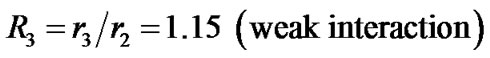
The centrifugal compressor selected for the study is a low speed centrifugal compressor. Detailed specifications of the compressor are given in Table 1.
As mentioned earlier four types of diffuser configurations are used for the study of impeller-diffuser interaction. The total number of diffuser vanes in VD configuration is 22 and that in LSVD is 11. The solidity (i.e. chord to spacing ratio) for the conventional vaned diffuser is 1.4 whereas for LSVD it is 0.7. In partial vaned diffuser configuration 11 diffuser vanes are fitted each on the shroud wall and on the hub wall in staggered manner. The vanes on the hub and shroud walls are staggered by half vane spacing. The height of the vane in partial vaned diffuser is 6 mm, which is less than the flow passage width. The vane profile is a circular arc for VD, LSVD and PVD. The leading edge shape is made semi elliptical with major axis four times minor axis. Minor axis is the thickness of the vane and it is equal to 4 mm. The trailing edge is also made semi elliptical shape with a major axis of 16 mm and minor axis of 4 mm. All the angles mentioned in Table 1 are measured with reference to the tangential direction.
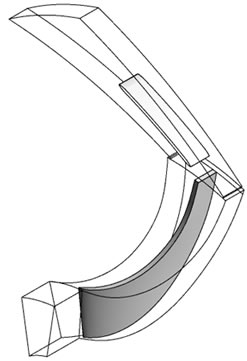
Numerical simulation of entire impeller blades and diffuser passage require large amount of computational time and computer memory. To avoid this, the computational model used for the simulation of VD and VLD configurations consists of a single diffuser vane and a single impeller blade passage. In PVD and LSVD configurations one diffuser vane passage and two impeller blade passages are modeled. This is done in order to make the area ratio at the interface of rotor and stator close to unity. Figure 1 shows the computational domain of the four above mentioned configurations.
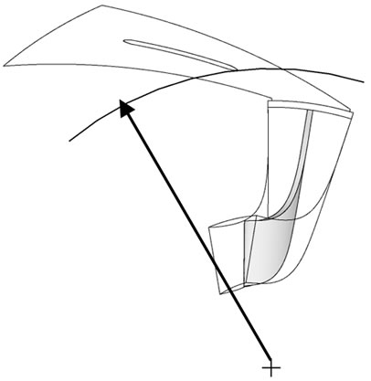
In vaned type configurations the intensity of impeller diffuser interaction is varied by varying the radial gap between impeller blade and diffuser vane (Figure 2). The leading edge of the diffuser vane is kept at two different radial locations; these are,
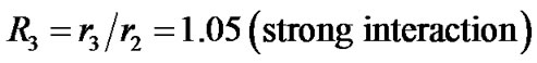
The diffuser chord length is fixed and is common for all these configurations. At each location the diffuser vane angle is set in such a way that the incidence angle is zero at design flow rate. Impeller tip clearance is set as 2% of the impeller width at outlet.
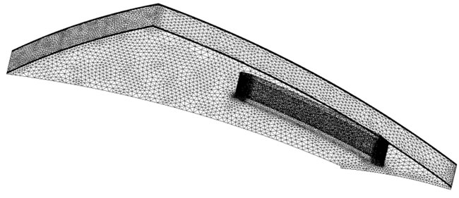
For steady state analysis the simulation is done at an instantaneous relative position between impeller blade and diffuser vane. Unstructured tetrahedral elements are used for meshing (Figure 3). Fine elements are given around the impeller blade, diffuser vanes and near to hub and shroud wall. Very fine elements are given at the leading edge, trailing edge and at the tip clearance region. Prism layers are attached to the walls. At least six prism
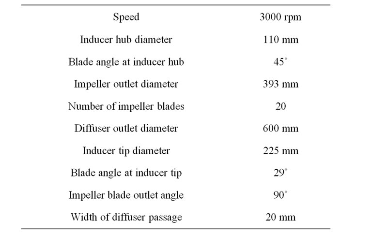
Table 1. Centrifugal compressor details.
 (a)
(a)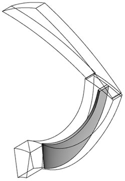 (b)
(b) (c)
(c)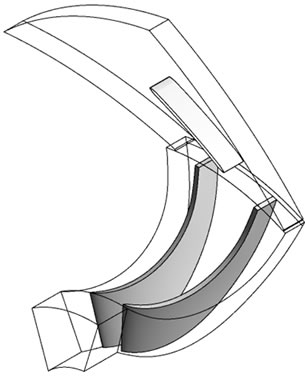 (d)
(d)
Figure 1. Computational model. (a) VD; (b) VLD; (c) LSVD; (d) PVD.
 (a)
(a)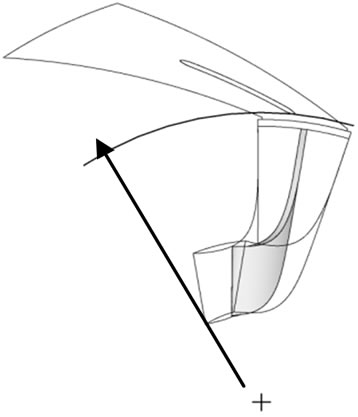 (b)
(b)
Figure 2. Diffuser vane leading edge locations for VD. (a) R3 = 1.05; (b) R3 = 1.15.
 (a)
(a)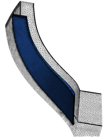 (b)
(b)
Figure 3. Computational mesh. (a) Diffuser; (b) Impeller.
layers are kept in the tip clearance region. The geometry modeling and meshing is done using ICEM CFD.
The study is carried out using Reynolds-Averaged Avier-Stokes simulations. A commercial software ANSYS CFX is used for this purpose. Stationary frame uniform total pressure and total temperature is given as boundary condition at the inlet. Specification of uniform inflow direction normal to the inlet plane is quite justified because the inlet boundary is moved away from the impeller.
The fluid used for simulation is air ideal gas. The specified heat transfer model used for the simulation is total energy model. The turbulence model is kω and turbulence intensity at inlet is given as 1%. The wall influence on flow of the shroud wall of the impeller domain is specified as counter rotating type, because in a stationary frame of reference the shroud wall does not rotate. At outlet, mass flow rate is specified as boundary condition. As the model contains a rotating (impeller) and a stationary domain (diffuser), suitable periodic interfaces are required between impeller and diffuser. The interface between impeller and diffuser is kept at R3 = 1.025 for all cases and connects both meshes together across the frame change. For the present steady state simulation frozen rotor model is used i.e. the simulation is done at an instantaneous relative position between impeller blade and diffuser vane. This model is robust and uses less computer resources than other interface models. The pitch ratio (i.e. area of impeller domain interface divided by area of diffuser domain interface) is 1.101. As the flow crosses the interface it is scaled to allow this type of geometry to be modeled. This results in an approximation of the inflow to the diffuser passage. To calculate the advection terms in the discrete finite volume equations high resolution scheme is used. ANSYS CFX uses a coupled solver, which solves the hydrodynamic equations as a single system. This solver uses a fully implicit discretization of the governing equations at any given time.
3. Validations
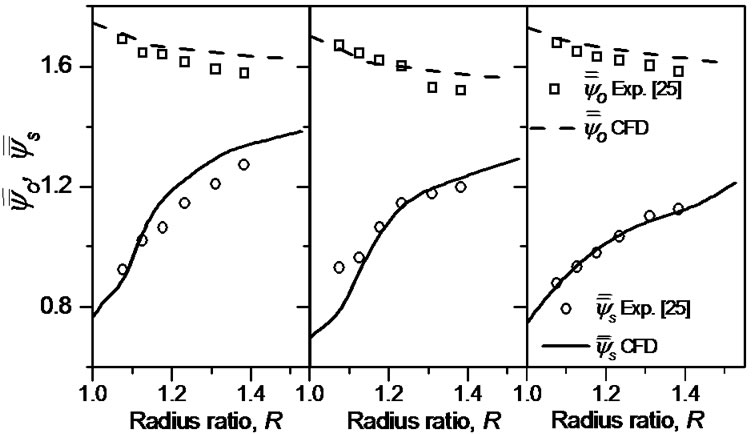
The results obtained from the simulations are compared with the experimental results of Issac [11]. A pre-calibrated three hole probe is used to measure the flow in the diffuser passage. Figure 4 shows variation of mass averaged total  and static pressure
  coefficient with respect to radius ratio, R, across the diffuser. Mass averaged value of pressure can be defined as follows,
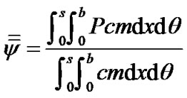
where 0 to s is the circumferential distance between the two consecutive diffuser vanes and b is the diffuser width.
4. Results and Discussions
4.1. Variation of Static Pressure inside Impeller
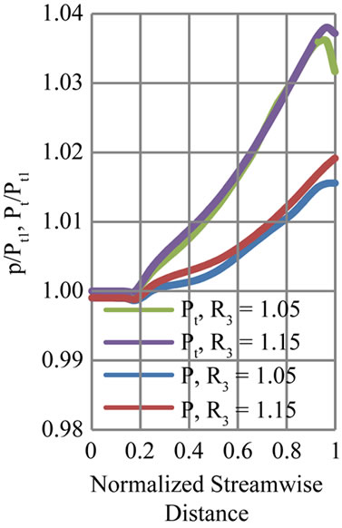
Variation of total to total (Pt/Pt1) and total to static pressure ratio (p/Pt1) from the impeller domain inlet to outlet at various interaction levels are shown in Figure 5. The X-axis represents normalized stream-wise distance. This is defined as the distance between computational inlet of impeller and interface between impeller and diffuser along a streamline. The inlet of the impeller domain which is 40 mm away from the leading edge of the impeller blade is represented by “0”. The impeller domain
 (a) (b) (c)
Figure 4. Comparison of experimental and computational results at design mass flow rate. (a) VD; (b) LSVD; (c) VLD.
 (a)
(a)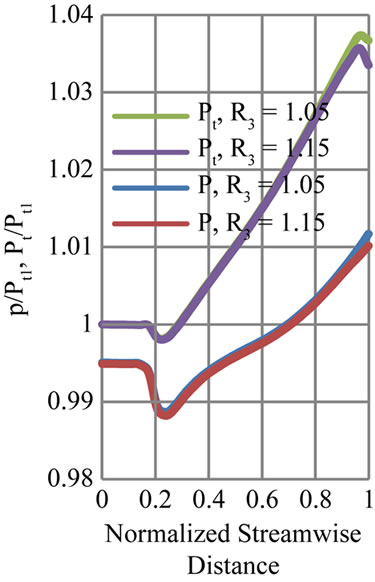 (b)
(b)
Figure 5. Variation of total to total (Pt/Pt1) and total to static pressure ratio (p/Pt1) inside the impeller. (a) VD; (b) LSVD.
outlet which is the interface between impeller domain and the diffuser domain is represented by “1”. The pressure values are mass averaged at each streamwise location. Hence this plot provides an overall picture of the diffuser vane effect on the impeller energy addition.
In the case of VD the variations are shown for above design mass flow rate of 0.965 kg/s (near choke). Differences are observed at the last twenty percent of the impeller domain, which indicates that the effects of interaction are not penetrated deep into the impeller flow at this mass flow rate.
For LSVD the pressure variations inside impeller are shown at below design flow rate (i.e. m = 0.423 kg/s). This flow rate is close to stall margin for LSVD. The static pressure rise is smaller for R3 = 1.05 compared to R3 = 1.15 configuration. The pressure ratio curve indicates that the effect of diffuser vane is felt throughout the impeller passage for a closer radial gap. The R3 = 1.05 configurations may be in the stall region at this mass flow rate. Keeping the diffuser vane away from the impeller can delay the stall inside the impeller. The effect of diffuser vane on the impeller energy addition is very small for PVD configurations (not shown here)
4.2. Flow Analysis inside Impeller Passage
Figure 6 shows the relative total pressure on the pressure surface (PS) and suction surface (SS) of impeller blade with at different mass flow rates. These contours are shown for the impeller with a vaneless diffuser at downstream. Relative total pressure represents the flow behavior inside a rotor correctly, as it is the sum of static pressure to the dynamic head based on the relative velocity. Due to the turning of the flow from the axial to radial direction a pressure gradient develops from hub to shroud.
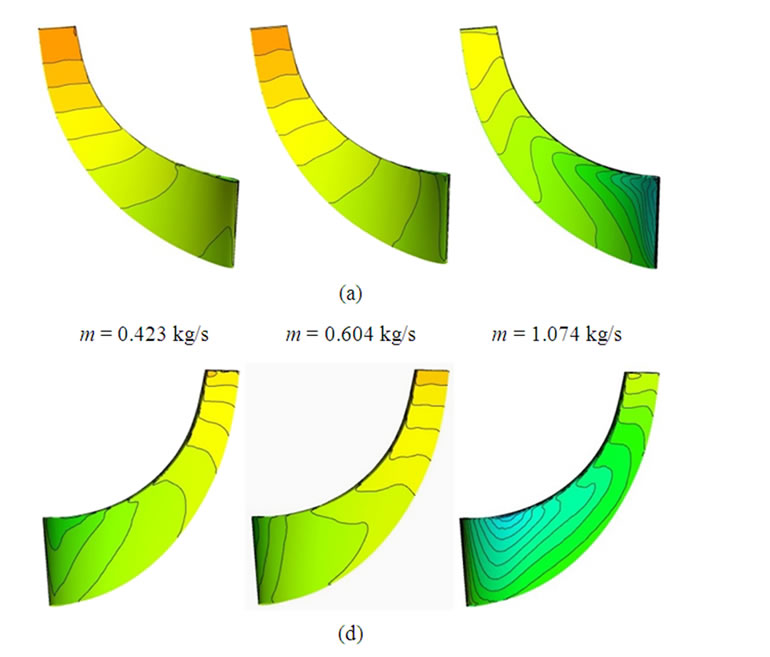
Figure 6. Relative total pressure contours on impeller blade (VLD): (a) Pressure surface; and (b) Suction surface.
This pressure gradient in the span-wise direction gradually comes down and becomes uniform at the exit of impeller blade. The pressure gradient in the hub to tip direction increases with the mass flow rate. Low relative total pressure is observed on the suction side near the axial to radial bend. The pressure gradient is higher on the suction surface and maximum gradient is observed on the inducer part. This pressure gradient and the centrifugal force cause the fluid movement from the hub to tip. This movement is observed from the relative velocity vectors plotted on a plane adjacent to the suction surfaces of the impeller blade (Figure 7). The upward movement of fluid is visible near the suction surface where the relative pressure gradients are high.
Kang and Hirsch (1999) pointed out that the relative total pressure gradient in the hub to shroud direction causes the low velocity wake region to move towards the shroud. To validate this, contours of non-dimensional meridional velocity are plotted on a plane normal to the throughflow direction at a streamwise location M = 0.5 (Figure 8). This plot has been shown only for impeller with VLD at downstream. The flow behavior inside the impeller at M = 0.5 is similar for other configurations also at design point.
Near the shroud a low velocity wake region is observed for all the mass flow rates. This low velocity region is spread throughout the shroud wall in the case of m = 0.423. As the mass flow rate increases the core of this wake region move towards the suction surface. This movement is under the influence of Rossby number and it has been reported by Inoue and Cumpsty (1984) and Kang and Hirsch (1999). For the present analysis a radial
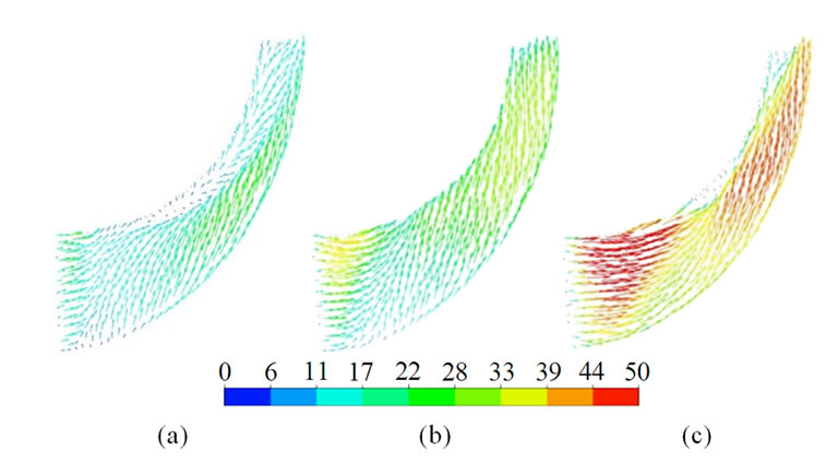
Figure 7. Relative velocity vectors near impeller blade suction surfaces (impeller with VLD). (a) m = 0.423 kg/s; (b) m = 0.604 kg/s; (c) m = 1.074 kg/s.
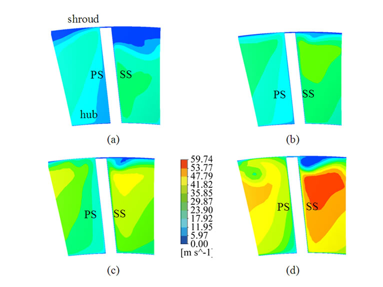
Figure 8. Contours of non-dimensional meridional velocity at M = 0.50, impeller with VLD. (a) m = 0.423 kg/s; (b) m = 0.604 kg/s; (c) m = 0.805 kg/s; (d) m = 1.074 kg/s.
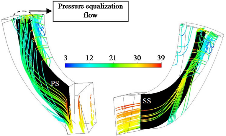
tipped impeller is used hence the flow at the exit of the impeller is not controlled by the Rossby number alone. Instead the exit flow is mostly under the influence of tip leakage and pressure equalization flow. Figure 9 shows the streamlines inside impeller with vaneless diffuser at m = 0.604. The streamlines show the movement of low energy fluid from the hub to the shroud on both sides of the impeller blade. From the pressure surface (PS) side this low momentum fluid pass through the tip clearance region as a jet flow (note the high velocity of the fluid inside the tip gap). This tip leakage flow interacts with the low momentum fluid on the suction surface (SS) causing the latter to roll down and move towards the exit. At the exit pressure equalization flow from the PS to SS pushes the low momentum fluid back in to the impeller passage. This causes further deceleration of the flow from suction side. The strength and location of the wake region at the exit of impeller blade is heavily depended upon the tip leakage flow and the pressure equalization flow. Shum et al. (2000) observed some variations in the
 (a) (b)
Figure 9. Streamlines showing the pressure equalization flow and tip leakage flow; view from (a) pressure surface and (b) suction surface; m = 0.604 kg/s.
impeller performance with tip leakage flows and also observed that the tip leakage flow is a function of the diffuser vane loading. To understand, how the impeller out flow varies with different types of diffusers, normalized meridional velocity contours are plotted at M = 0.97 (i.e. near trailing edge of the impeller blade).
4.3. Flow Behavior at Impeller Exit (VLD and VD)
Figure 10 shows the meridional velocity contours at M = 0.97 for impeller with VLD for four mass flow rates. The low energy zone observed at M = 0.5, near the shroud, is strengthened by the tip leakage and pressure equalization flow. As the mass flow rate increases the pressure equalization and tip leakage flow are increases hence at m = 1.074 the wake move closer to the blade suction surface. The jet region, which is observed at the hub suction side corner, moves towards the pressure surface of the impeller as the flow rate increases.
Figure 11 shows the non-dimensional meridional velocity contours at strong interaction level (R3 = 1.05) for VD. At m = 0.423 large wake region is observed near the blade suction surface. At closer radial gap the back pressure from the diffuser assists the reverse flow near the shroud. At higher mass flow rate the core of the reverse flow region moves away from the suction surface. It is quite interesting to note that at design mass flow rate (m = 0.604) the reverse flow region is much higher than the slightly above design flow (m = 0.805).
When the diffuser vane leading edge is kept at R3 = 1.15 (Figure 12) the strength of the wake region and reverse flow region reduce are reduced at lower mass flow rates. The nature of the velocity contours is almost similar to that of R3 = 1.05. Here also, smaller wake region is observed at slightly above design flow rates (i.e. at m = 0.805).
To understand this phenomena in detail, circumferen-
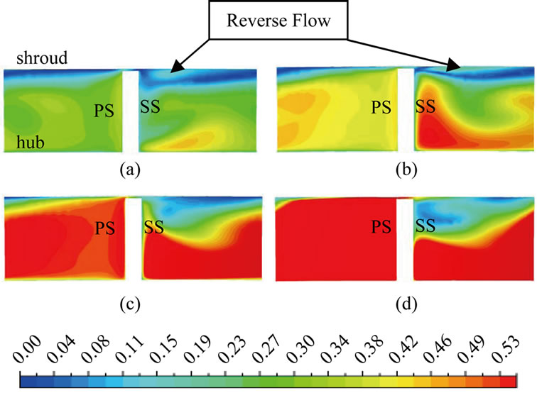
Figure 10. Contours of non-dimensional meridional velocity inside impeller at M = 0.97 (impeller with VLD). (a) m = 0.423 kg/s; (b) m = 0.604 kg/s; (c) m = 0.805 kg/s; (d) m = 1.074 kg/s.
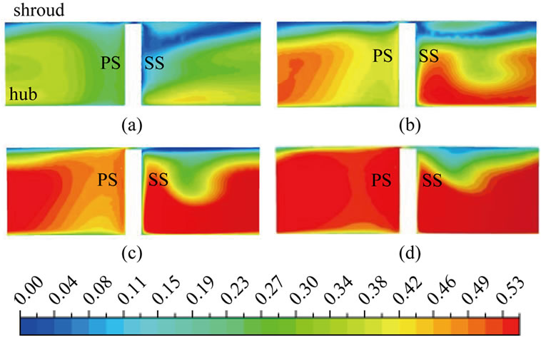
Figure 11. Contours of non-dimensional meridional velocity inside impeller at M = 0.97; R3 = 1.05; (impeller with VD). (a) m = 0.423 kg/s; (b) m = 0.604 kg/s; (c) m = 0.805 kg/s; (d) m = 1.074 kg/s.
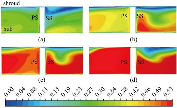
Figure 12. Contours of non-dimensional meridional velocity inside impeller at M = 0.97; R3 = 1.15; (impeller with VD). (a) m = 0.423 kg/s; (b) m = 0.604 kg/s; (c) m = 0.805 kg/s; (d) m = 1.074 kg/s.
tially mass averaged flow angle at M = 1.01 is plotted (Figure 13). At design flow rate, the flow angle is almost constant up to 70 percent of the span. Near the shroud flow becomes highly tangential. The negative flow angle near the shroud indicates the reverse flow at that location. Because of the small flow angle near the shroud, flow does not enter through the leading edge instead it hits on the upper convex surface of the diffuser vane (often referred as positive incidence). The flow then turn around the leading edge and flows along the lower concave surface of the diffuser vane, before it separates (Figure 14(a)). This flow enhances the reverse flow into the impeller passage. At m = 0.805, flow angle near shroud become more radial, hence there is not much reverse flow to the impeller (Figure 14(b)).
A look at the incidence angle plot (Figure 15) reveals that most of the span the incidence is negative at m = 0.805. Large positive incidence near the shroud is not
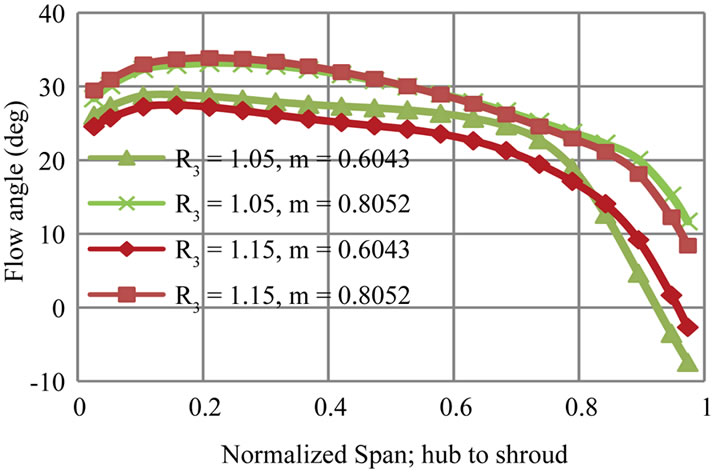
Figure 13. Circumferentially mass averaged flow angle in span-wise direction (0 = hub, 1 = shroud).
 (a)
(a)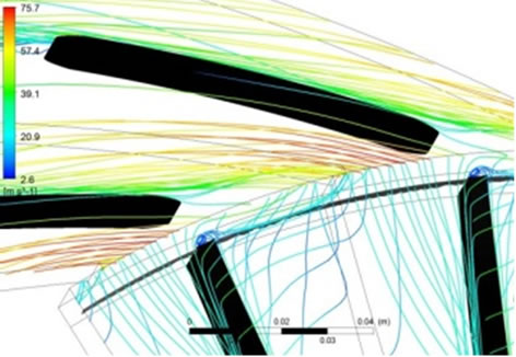 (b)
(b)
Figure 14. Streamlines show the flow behavior inside the diffuser for VD at R3 = 1.05. (a) m = 0.604 kg/s; (b) m = 0.805 kg/s.
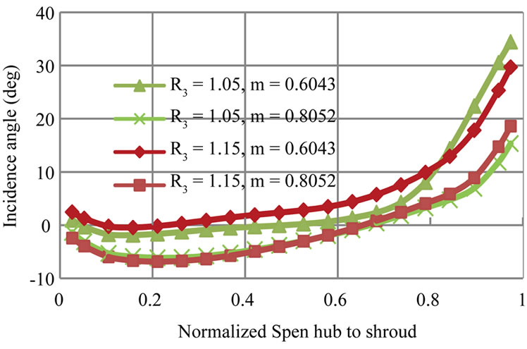
Figure 15. Circumferentially mass averaged incidence angle in span-wise direction (0 = hub, 1 = shroud).
observed at m = 0.805. Hayami et al. [12] found that a negative incidence of 2˚ to 3˚ gives better performance to low solidity vaned diffuser. Similarly Hohlweg et al. [13] also reported that the maximum diffuser performance is obtained with a negative incidence of 4.1˚. Here it is found that small negative incidence is desirable in order to reduce the losses at the impeller exit. A definite value for the optimum incidence cannot be possible as the flow angle varies largely along the span.
4.4. Flow Behavior at Impeller Exit (LSVD and PVD)
The flow behavior inside the impeller with LSVD and PVD are dealt separately because the relative angular positions of impeller blade and diffuser vane are different from that of VD (ref. Figure 1).
Figure 16 shows the non-dimensional meridional velocity contours at R3 = 1.05 and at R3 = 1.15 respectively for LSVD. These are shown for a mass flow rate of m = 0.423 kg/s. There are notable difference regarding the strength and location of wake region between these two configurations. At R3 = 1.05 wake region is located at the mid-passage close to the shroud. For R3 = 1.15 the core of the reversed flow region is located at the shroud-suction surface corner. The streamline plot (Figure 17) give an insight into the flow behavior in these two configurations. When the diffuser vanes are closer to the impeller the reverse flow enhances the tip leakage flow near the impeller exit. This can be clearly observed from the streamlines pattern. Corresponding static entropy contours shows an increase in the entropy generation at this location (not shown here). When there is sufficient radial gap, the separated flow from the diffuser vane does not influence the impeller exit flow. Hence the losses at the impeller exit are also smaller.
The non-dimensional meridional velocity contours for the two PVD configurations are shown in Figure 18. The partial vaned diffuser does not affect the impeller exit
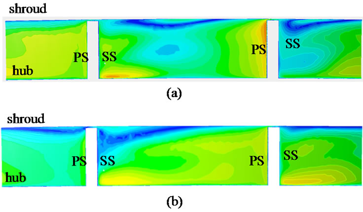
Figure 16. Contours of non-dimensional meridional velocity inside impeller (LSVD) at M = 0.97; m = 0.423 kg/s. (a) R3 = 1.05; (b) R3 = 1.15.
 (a)
(a)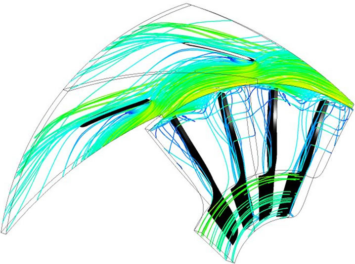 (b)
(b)
Figure 17. Streamline plots showing enhanced tip leakage flow for R3 = 1.05. (a) R3 = 1.05; (b) R3 = 1.15.
flow adversely. On the contrary it stabilizes the flow near the shroud. Comparing the exit flow conditions of PVD with VLD reveals that the strength of the reverse flow region is reduced with the use of PVD.
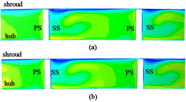

Figure 18. Contours of non-dimensional meridional velocity at M = 0.97, impeller with PVD; m = 0.4227 kg/s. (a) R3 = 1.05; (b) R3 = 1.15.
5. Conclusions
A computational study has been conducted to analyze the effects of diffuser vane on impeller exit flow. Three types of vane diffusers are used; a conventional vaned diffuser (VD), low solidity vaned diffuser (LSVD) and a partial vaned diffuser (PVD). The diffuser vane leading edge is kept at different radial locations to understand its influence on the impeller exit flow. Above design flow rate, the diffuser vane affects only the last twenty percent of the impeller flow. However below design flow rate, keeping vane closer to the impeller can cause an early stall within the impeller. Detailed flow analysis inside the impeller passage shows that the strength and location of the wake region at the exit of impeller blade is heavily depended upon the tip leakage flow and the pressure equalization flow.
Even at design flow rate the flow angle near the shroud is too small and hence it causes large positive incidence. This enhances the reverse flow near shroud. A small negative incidence at the diffuser vane is desirable in order to reduce the losses at the impeller exit. Partial vane diffusers do not affect the impeller exit flow adversely instead they stabilize the impeller separation region at lower flow rates.
REFERENCES
- M. Inoue and N. A. Cumpsty, “Experimental Study of Centrifugal Impeller Discharge Flow in Vaneless and Vaned Diffusers,” ASME Journal of Engineering Gas Turbines Power, Vol. 106, No. 2, 1984, pp. 455-467. doi:10.1115/1.3239588
- J. Moore and J. G. Moore, “Calculation of Three-Dimensional, Viscous Flow and Wake Development in Centrifugal Impeller,” Journal of Engineering for Gas Turbines and Power, Vol. 103, No. 2, 1981, 6 pp.
- J. D. Denton, “The Use of a Distributed Body Force to Simulate Viscous Effects in 3D Flow Calculations,” ASME 31st International Gas Turbine Conference and Exhibit, Duesseldorf, 8-12 June 1986, 8 pp.
- W. N. Dawes, “A Simulation of the Unsteady Interaction of a Centrifugal Impeller with Its Vaned Diffuser: Flows Analysis,” ASME Journal of Turbomachinery, Vol. 117, No. 2, 1995, pp. 213-222.
- R. M. Chriss, M. D. Hathaway and J. R. Wood, “Experimental and Computational Results from the NASA Lewis Low-Speed Centrifugal Impeller at Design and Part-Flow Conditions,” ASME Journal of Turbomachinery, Vol. 118, No. 1, 1996, pp. 55-65.
- Ch. Hirsch, S. Kang and G. Pointel, “A Numerically Supported Investigation of the 3D Flow in Centrifugal Impellers, Part 1: Validation Base,” ASME Paper No. 96-GT-151, ASME TURBO EXPO, Birmingham, 1996.
- S. Kang and Ch. Hirsch, “Numerical Simulation and Theoretical Analysis of the 3D Viscous Flow in Centrifugal Impellers,” TASK Quarterly, Vol. 5, No. 4, 2001, pp. 433-458.
- M. Schleer and R. S. Abhari, “Clearance Effects on the Evolution of the Flow in the Vaneless Diffuser of a Centrifugal Compressor at Part Load Condition,” ASME Journal of Turbomachinery, Vol. 130, 2008, pp. 1-9.
- D. Eckardt, “Detailed Flow Investigations within a High Speed Centrifugal Compressor Impeller,” ASME Journal of Fluids Engineering, Vol. 98, No. 3, 1976, pp. 390-402. doi:10.1115/1.3448334
- Y. K. P. Shum, C. S. Tan and N. A. Cumpsty, “Impeller-Diffuser Interaction in a Centrifugal Compressor,” ASME Journal of Turbomachinery, Vol. 122, No. 4, 2000, pp. 777-786. doi:10.1115/1.1308570
- J. M. Issac, “Performance and Flow Field Measurements in Different Types of Diffusers of a Centrifugal Compressor,” Ph.D. Thesis, Department of Mechanical Engineering, Indian Institute of Technology (IIT) Madras, Chennai, 2004.
- H. Hayami, Y. Senoo and K. Utsunomiya, “Application of a Low Solidity Cascade Diffuser to Transonic Centrifugal Compressor,” ASME Journal of Turbomachinery, Vol. 112, No. 1, 1990, pp. 25-29. doi:10.1115/1.2927416
- W. C. Hohlweg, G. L. Direnzi and R. H. Aungier, “Comparison of Conventional and Low Solidity Vaned Diffusers,” ASME Paper 93-GT-98, ASME TURBO EXPO, Cincinnati, 1993.
Nomenclature
b Diffuser width
m Mass flow rate
M Normalized streamwise distance
p Pressure
r Radius
R Radius ratio
S Normalized span-wise distance
Subscripts
0 Total state
1 Inlet
2 Impeller trailing edge
3 Diffuser vane leading edge
s Static state
NOTES
*Corresponding author.