World Journal of Engineering and Technology
Vol.06 No.01(2018), Article ID:82723,13 pages
10.4236/wjet.2018.61011
Analysis of Striation Formation and Suppression Strategy on Upper Edge of Cutting Surface in Laser Cutting
Chao Li, Dengfei You
Shanghai Xinli Machinery Factory, Shanghai, China

Copyright © 2018 by authors and Scientific Research Publishing Inc.
This work is licensed under the Creative Commons Attribution International License (CC BY 4.0).
http://creativecommons.org/licenses/by/4.0/


Received: December 21, 2017; Accepted: February 25, 2018; Published: February 28, 2018
ABSTRACT
Metal laser cutting belongs to mature laser material processing technologies in industry applications. However, without understanding of the mechanism underlying the overall process, the improvement of the cutting quality is restricted. In this paper, an instantaneous melt removal model is presented to describe the process of material removal and striation formation. In the temperature field calculation, melted metal layer is removed when it grows to an assumed thickness. The effects of cutting parameters including cutting speed, gas pressure and laser power on the shape of striation are discussed. A novel method of getting striation free cutting surface is presented. Finally, laser cutting experiments of mild steel is conducted to validate the model. The striation variation trend can be well predicted by the model presented here and the disagreement may be caused by the coupling effect of cutting speed and critical thickness value.
Keywords:
Fusion Cutting, Striation, Instantaneous Removal, Laser Power Modulation

1. Introduction
Laser processing technology has been used in industry with the properties of non-contact, high brightness, coherence and monochromaticity. Of the applied technologies, laser cutting is widely used with the features of high efficiency, small heat-affected zone and good cutting quality. However, on the resulting cutting surface, periodic distributed striation often exists along the cutting direction, which induces poor laser cutting quality. Laser cutting of metal sheet is often used for the blanking of butt welding process. Because of the striations, the weld strength is dramatically reduced.
There are generally three kinds of striation distributed on the cutting surface [1] in the application of laser cutting. The first kind of striation appears on the upper edge, showing a regular and periodic shape. No recast metal is found in this area. In comparison with the others, the second kind occupies a respectively small area, locating in the middle. Its frequency is twice that of the first kind and little recast material is found here. The third kind of striation covered by large amount of recast metal is found on the bottom edge, with an irregular shape. Different mechanisms were proposed through experiments or theoretical calculation. Arata, Maruo [2] firstly used high-speed camera to observe the cutting front in oxygen-assisted laser cutting. It was concluded that side burning is the cause. Ivarson, Powell [3] developed a cyclic oxidation model to theoretically explain the periodic combustion process mentioned above. However, striation still exists in inert gas assisted cutting without oxidation reaction. Makashev, Asmolov [4] investigated the nonstationarities in melt removal. It is found that during the melting process of cutting front, the melting layer grows thicker. When the thickness reaches a critical value, the melt is removed by the assisted gas flow. Li, Sobih [5] firstly got striation free cutting surface for 2 mm thick mild steel by ensuring a continuous melting process. The experimental plates were thin that only the first kind of striation would appear and needs to be dealt with. Hirano and Fabbro [6] observed the melt flow on the top part of the kerf. It was found that melt accumulation was removed along the depth direction periodically. Yudin and Kovalev [7] investigated the cutting front directly by cutting the Rose alloy, using a high-speed camera. The phenomenon of striation formation during the melt flow on the cut surface was observed. Schulz, Kostrykin [8] thought that the fluctuation of laser absorption at the cutting was the cause. The melt accumulation phenomenon from the experiments observation was not considered in the presented model. There are two plausible reasons for this melt instability. One is that with the gas shearing force and surface tension of the melt layer, the melt is removed in liquid drops. The other is as the melt layer becomes hotter and thicker, the viscosity of the melt decreases, which can be easily blow away by the gas flow. The latter is closely related to the temperature at the cutting front which is influenced by the laser absorption.
In this paper, the melt film formation and varying power absorption under laser irradiation are both considered in a dynamic process. The melted layer adhering to the cutting front is removed at a critical thickness S0. Then a one dimensional model was established to predict the depth and wavelength of striation. The model characterizes the correlation between the process parameters and striation geometry, while providing the guidelines in obtaining striation-free cutting surface in laser cutting application. Finally, sheet metal cutting experiments were performed.
2. Melt Removal
The workpiece is fixed with the moving laser incidence absorbed on the cutting front. The multiphase flow model (assisting gas flow, melt and solid metal) is simulated with the volume fluid method in FLUENT. The schematic of melt formation and removal is shown in Figure 1. In this dynamic process, the cutting front is divided into two: the heating front and the cutting front. The former is where laser power is absorbed and the latter is the phase transition boundary between the liquid and solid metal. In the initial stage, the laser approaches and heats the edge of the blank. When its temperature reaches the melting temperature Tm, the melting front grows along the laser beam scanning direction and the thickness of the melting layer (red part) increases. When the thickness reaches the critical value S0, the melt is assumed to be removed instantaneously. The parameter S0 is the maximal thickness melt film layer can increase to before it is removed. It should be result of the balance among the recoil pressure, surface tension, and assisted gas pressure.
In the instantaneous removal model, the heat transfer problem involved is the temperature variation of the cutting front caused by varying distances between the cutting front and the centerline of the laser beam. In the calculation, the laser heat source adopts TM0 mode (i.e. Gaussian power distribution). The heat absorbed by the metal is usually characterized by the absorption coefficient A0, which is determined by surface topography, incident angle, laser polarization, temperature and so on. It is assumed to be constant in the formulation. The intensity in the coordinate is depicted as
(1)
where PL is the laser power, X0 is the laser beam center and W0 is the focused laser radius.
The heat equation is as follows:
(2)
where α is the thermal diffusion coefficient.
As for the boundary conditions, there are two cases to be considered. When the temperature of the heating front T(Xb, t) is less than the melting temperature Tm, the cutting front is in the heating stage.

Figure 1. Schematic of instantaneous melt removal.
(3)
where Xb is the heating front and k is the thermal conductivity.
When T(Xb, t) is equal to Tm, the melting front Xm moves to the positive direction of the x axis at the melting speed. V0 is the cutting speed.
(4)
where Xm is the melting front, L is the latent heat of melting, ρ is the density of melt.
The heat equation is resolved in a semi-infinite solid and the infinite boundary condition is
(5)
The laser power is absorbed at the heating front Xb to move the melting front Xm forward. The relation between these two fronts is
(6)
where S0 is an empirical value which should be in proportional to the striation depth. The usual experiment striation depth lies in 30 - 80 μm. Divided by the laser spot (110 μm), this dimensionless parameter is equal to 0.5 for typical cutting parameters in the model.
The variables in the equations above have different dimensions. For the convenience of numerical calculation, three dimensionless variables temperature θ, length ξ, time t and three dimensionless constants, Peclet number Pe, laser power PA, and inverse Stefan number are introduced to acquire dimensionless formulations.
(7)
where Pe is the ratio of the advective transport rate to the diffusive transport rate, and is the ration of the latent heat to the sensible heat.
When it comes to the melting stage, the heat transfer happens in a moving melting boundary, i.e. the Stefan problem. A transformation is introduced as follows:
(8)
The Equations (2)-(5) are then transformed into
(9)
(10)
(11)
(12)
The Equations (9)-(12) are resolved using the finite difference method (FDM) in Mathematica®.
3. Cutting Parameter Analysis
The temperature field in the metal is shown in Figure 2. The steady state is under the condition that S0 is equal to 0. The difference between the heating state and the melting state is the temperature at the melting front y = 1. In the steady state and the melting state, the temperatures at the melting front are all held to be the melting point Tm, while the temperature here is a little low in the heating state. From the temperature distribution, it can be seen that the temperature in the melting state in the region 0 < y < 1 is lower than that in the steady state. The reason is that the melting speed in the melting state is bigger, and more energy is used to melt the metal.
Figure 3 shows the evolution of the cutting front. It is clear that the periodic variation shape is displayed in the melting front and the heating front. At the heating stage, the two boundaries coincide with each other. At the melting stage, the melting front moves ahead of the heating front. When the thickness of the melt layer increases to the critical value S0, the melt is removed instantaneously and the heating front moves forward in a step.
The distance between the melting front and the center of the laser beam determines the energy absorption rate in melting the metal. And in the cutting process, its variation is cyclic as shown in Figure 4. As mentioned earlier, the formation of cutting striation is influenced by the removal of the melt. The

Figure 2. Temperature distribution along the cutting path.

Figure 3. Evolution of melting boundary and front boundary ,

Figure 4. Evolution of the distance between the laser beam center and melting boundary ,
characterized distance reflects the phase transition boundary, i.e. the shape of striation.
3.1. Effect of Cutting Speed Pe
As shown in Figure 5, with the increasing of the cutting speed, the wavelength of the striation decreases. For a fixed critical value S0, the higher cutting speed means faster energy input rate and smaller temperature variation at the cutting front.
3.2. Effect of Critical Thickness S0
As shown in Figure 6, with the increasing of S0, the amplitude and wavelength of the striation grow. Obviously, the effect of S0 has a contrary trend compared with that of Pe. S0 is influenced by the assisted gas flow and the dimensionless Pe, which reflects the heat input.
3.3. Effect of Laser Power PA
In Figure 7, it seems that PA has little impact on the shape of striation. But another

Figure 5. Effect of on striation shape, (a)-(d) ,

Figure 6. Effect of on the striation shape, (a)-(d) ,

Figure 7. Effect of on striation shape (a)-(d) , ,
result which should be concerned is that the mean value of the distance increases with a bigger PA. For a fixed cutting speed, the power absorbed by the heating front is almost constant in the steady cutting process. As a result, if the simulative laser power PA increases, it is reasonable that the distance between the laser center and the cutting front is bigger. Back to the analysis in Section 3.1 and 3.2, mean value of the distance decreases when Pe increases with a bigger S0.
4. Striation Suppression
Through the parameter analysis above, the variation trend of striation is obtained. Based on the inspiring result, striation suppression strategy is presented according to the instantaneous melt removal model. In the model, variation of the distance is used to approximately represent the shape of striation. When this value is kept constant, the formation and removal of melt layer become continuous without heating stage. Then the striation free condition is built. The laser power directly affects the melting speed. Therefore, the modulation of laser power will directly control this variation, while suppressing the formation of striation.
Assuming that PA is the temporal function, i.e. PA = PA(τ) and the melting speed is equal to the cutting speed. The time dependent laser power is obtained as
(13)

Figure 8. (a) Laser power of exponential distribution, constant distribution, cosine distribution, square distribution and triangle distribution (b) Striation shape .
This is the exponential distribution as shown in Figure 8(a). For comparison, laser power of constant distribution, cosine distribution, square distribution and triangle distribution are also selected to conduct striation suppression simulation. As expected, power modulation has a significant impact on the formation of striation. The idle exponential power distribution completely eliminates the striation. Because of the existence of numerical calculation errors, the shape of striation in Figure 8(b) shows little fluctuation under exponential modulation. Other kinds of power modulation don’t present the suppression effect.
5. Experiment Results
The experiment of mild steel laser cutting was conducted to validate the model. Rofin DC030 CO2 laser with a conical nozzle is adopted. The laser power was 3000 W and nitrogen was used as the assisting gas. The mild steel was Q235-A. The cutting parameters are listed in Table 1.
Figure 9 shows the top view and front view of the upper edge on the cutting surface. In the top view, it can be seen clearly that the boundary left after the

Table 1. Laser cutting parameters and material properties for the mild steel.
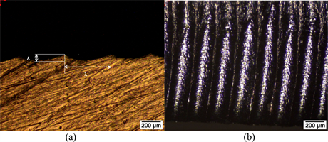
Figure 9. (a) Top surface of the kerf (b) Cutting surface
, and 

Figure 10. Striation shape for different cutting speed (a)  (b)
(b)  (c)
(c)  (d)
(d) .
.
melt removal by the gas flow. The circular cavity is the melt melting result of the laser heat source. And the tips between the cavities are formed by the melt removal. The amplitude A and the wavelength λ of the striation are measured to evaluate the striation in the following discussion. Striations on the resulting surface in the experiments show different morphology at increasing cutting speed as shown in Figure 10.
Figure 11 shows the wavelength and amplitude curve of striation at different speeds. It can be found that with the increasing of the cutting speed, the wavelength becomes bigger and the amplitude decreases. This result conforms to that in the experiment analysis in reference [9] . Although the model predicts the same tendency with the experimental results, both striation depth and wavelength
 (a)
(a) (b)
(b)
Figure 11. Shape variation of striation with different cutting speed (a) wavelength (b) amplitude.
are underestimated. This discrepancy could be come from the difference between the real melt lay thickness and the critical thickness S0 which is assumed to be 0.5. The parameter also depends on the varying cutting velocity. However, even increasing the cutting speed until the metal couldn’t be cut through, the striation free cutting surfaces weren’t obtained.
The striation suppression strategy: exponential power modulation requires the laser power to be reduced by hundreds of watts in one millisecond that exceeds the operating range of the controller. Although the validation experiments aren’t performed, the relation between the striation elimination and laser power modulation is clearly seen.
6. Conclusions
The formation of striation on the cutting surface is determined by the evolution and the removal of the liquid melt layer. The presented instantaneous melt removal model predicts the variation trend of the wavelength and the amplitude of the striation, so that striation-free cutting surface is possible to be obtained by appropriate cutting strategy. Based on the above model, a striation suppression strategy based on the laser power modulation is presented. However, power modulation on laser cutting machine now is very hard to be realized, and this modulation method deserves further study. The results obtained are summarized as follows:
1) Laser cutting mechanism consists of heating stage and melting stage. The discontinuous melting process because of the existence of heat stage is the cause of wavelike striation.
2) Laser cutting parameters have an important impact on the shape of striation. The increase of cutting speed contributes to striation suppression.
3) The laser power exponential temporal distribution eliminates the striation theoretically derived by the model. Further experiments are needed to verify this cutting strategy.
Cite this paper
Li, C. and You, D.F. (2018) Analysis of Striation Formation and Suppression Strategy on Upper Edge of Cutting Surface in Laser Cutting. World Journal of Engineering and Technology, 6, 201-213. https://doi.org/10.4236/wjet.2018.61011
References
- 1. Dowden, J. (2009) The Theory of Laser Materials Processing: Heat and Mass Transfer in Modern Technology. In: Springer Series in Materials Science, Vol. 119, Springer, Dordrecht, 315-338. https://doi.org/10.1007/978-1-4020-9340-1
- 2. Arata, Y., et al. (1979) Dynamic Behavior in Laser Gas Cutting of Mild Steel (Welding Physics, Processes & Instruments). Transactions of JWRI, 8, 175-186.
- 3. Ivarson, A., et al. (1994) The Oxidation Dynamics of Laser Cutting of Mild Steel and the Generation of Striations on the Cut Edge. Journal of Materials Processing Technology, 40, 359-374. https://doi.org/10.1016/0924-0136(94)90461-8
- 4. Makashev, N.K., et al. (1994) Gas Hydrodynamics of CW Laser Cutting of Metals in Inert Gas. Proceedings of SPIE—The International Society for Optical Engineering, 2257, 2-9.
- 5. Li, L., Sobih, M. and Crouse, P.L. (2007) Striation-Free Laser Cutting of Mild Steel Sheets. CIRP Annals—Manufacturing Technology, 56, 193-196. https://doi.org/10.1016/j.cirp.2007.05.047
- 6. Hirano, K. and Fabbro, R. (2011) Experimental Investigation of Hydrodynamics of Melt Layer during Laser Cutting of Steel. Journal of Physics D: Applied Physics, 44, 105502-105513. https://doi.org/10.1088/0022-3727/44/10/105502
- 7. Yudin, P. and Kovalev, O. (2009) Visualization of Events inside Kerfs during Laser Cutting of Fusible Metal. Journal of Laser Applications, 21, 39-45. https://doi.org/10.2351/1.3071497
- 8. Schulz, W., et al. (1999) Dynamics of Ripple Formation and Melt Flow in Laser Beam Cutting. Journal of Physics D: Applied Physics, 32, 1219-1228. https://doi.org/10.1088/0022-3727/32/11/307
- 9. Chen, K. and Yao, Y.L. (1999) Striation Formation and Melt Removal in the Laser Cutting Process. Journal of Manufacturing Systems, 18, 43-53. https://doi.org/10.1016/S0278-6125(99)80025-9