Int'l J. of Communications, Network and System Sciences
Vol.1 No.4(2008), Article ID:153,8 pages DOI:10.4236/ijcns.2008.14044
Mathematical Formulations of Signal Propagation in Ultra-Wideband Transceiver Systems under a UWB Channel Environment with an Extension of Frequency Offset Correction
G. S. S. School of Telecommunications, Indian Institute of Technology Kharagpur, India
Email: debarati@gssst.iitkgp.ernet.in
Received April 4, 2008; revised August 29, 2008; accepted October 14, 2008
Keywords: Multi-Band OFDM, Signal Propagation, Transceiver, Ultra-Wideband
Abstract
This paper analyzes mathematically the crucial aspects of signal processing in a Multi-Band (MB) Orthogonal Frequency Division Multiplexing (OFDM) based system considering Ultra-Wideband (UWB) channel environment. In the process of analysis, it emphasizes the significant features of UWB receiver design in comparison with ‘conventional’ narrow-band system. The analysis shows that the high dispersive nature of a frequency selective UWB channel effects the design of different signal processing blocks like pre-select filter, low noise amplifier (LNA) and analog-to-digital (A/D) converter in the receiver front end. The characteristic functions of each of these stages are now dominated by the channel characteristics and it needs to be modified accordingly. This analysis is extended further with the study of frequency offset error and its correction. The unbiased Cramer Rao Lower Bound (CRLB) of estimation error is calculated and supported by computer simulation. The performance of an MB-OFDM system with frequency offset correction in terms of Bit-Error-Rate (BER) is also reported.
1. Introduction
The multi-band orthogonal frequency division multiplexing (MB-OFDM) based transmission scheme for ultrawideband (UWB) has attracted keen interest of researchers in these days. MB-OFDM has made UWB commercially more viable than ‘code-division multiple access’-based and ‘impulse-radio-based’ UWB systems for short range (<20m) high bit rate (>480Mbps) wireless applications.
However, it is essential to understand the crucial aspects of different signal processing stages in a UWB transceiver system that make a UWB receiver design significantly different compared to a narrow-band receiver design. Detailed mathematical studies on a UWB transceiver provides insights and helps in understanding the important aspects of a UWB receiver design which is the main aim of this work. Hence, there is a strong need for carrying on such an analysis for an MB-OFDM UWB system.
In this work, we first analyze an MB-OFDM UWB transmitter-receiver under a realistic UWB channel environment considering perfect timing and frequency offset estimation. Then, the study is extended to evaluate the performance of the system incorporating frequency offset errors through mathematical analysis supported by computer simulations.
The rest of this paper is organized as follows: Section 2 deals with the signal analysis in MB-OFDM transceiver. The ultra-wideband channel is modeled in Section 3. Signal analysis in an MB-OFDM receiver is presented in Section 4. Performance of the system with frequency offset error correction is analyzed in Section 5. It also shows the close match between calculated Cramer Rao Lower Bound (CRLB) of estimated error with simulation result. Section 6 figures out simulation results with some relevant discussion. Important concluding remarks with the summary of the paper are included in Section 7.
2. Signal Analysis in an MB-OFDM Transmitter
2.1. MB-OFDM System Specification
The Federal Communications Commission (FCC) has allotted 7.5GHz wide bandwidth for UWB transmission. The MB-OFDM system divides this unlicensed spectrum into fourteen (14) bands [1]. OFDM symbols are transmitted by frequency hopping over the bands. The block diagrams of a UWB transmitter and receiver considered for this study are shown in Figure 1 and Figure 2.
Let {X(k)} be the QPSK modulated complex sequence of symbols to be transmitted using OFDM (= T6 signal point in transmitter in Figure 1). A complex base band OFDM symbol can be obtained using N point Inverse Fast Fourier Transformation (IFFT) represented as
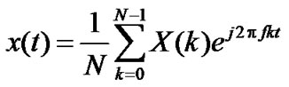 ; 0≤t<T
= 0 elsewhere (1)
where, f = sub-carrier spacing. Taking samples at t = nTS, Equation (1) can be written as
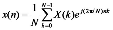 (2)
(2)
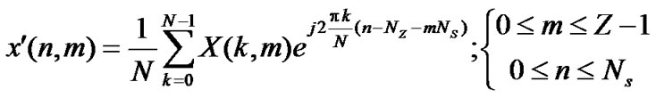
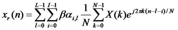
where, N = number of samples over duration T. Correspondingly, the n-th sample of the m-th OFDM symbol can be shown as
 ; 0≤m ≤ Z-1 (3)
where, ‘Z’ is the number of OFDM symbols transmitted.
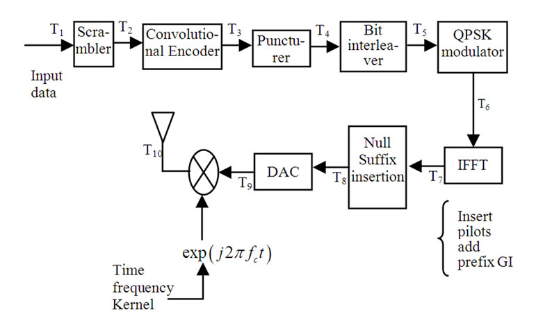
Figure 1. Multiband OFDM UWB transmitter.

Figure 2. Multiband OFDM UWB receiver.
2.2. Cyclic Prefix Insertion
In MB-OFDM transmission, zero-padded bits are added in place of cyclic prefix to compensate the multipath effect. Let, NZ number of Zero padded bits (ZP) and Ng number of guard bits (for inter band synchronization in MB-OFDM) are added with ‘N’ point IFFT output to construct one MB-OFDM symbol. The total number of samples ‘Ns’ in one OFDM symbol is given as, Ns = N+
NZ + Ng. Hence, from Equation (2)
x' (n) = 0, for 0 ≤ n ≤ Nz -1
= x(n-Nz), for Nz ≤ n ≤ N+Nz-1
= 0, for N+Nz ≤ n ≤ N+Nz+Ng-1
(4)
Similarly from Equation (3) (at T8 in Figure 1),
2.3. Signal Passing through DAC
After IFFT and zero padding, the signal (5) is passed next through a Digital to Analog Converter (DAC) block. The DAC operation involves two steps: firstly, conversion of the samples  into a sequence of impulses given as
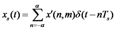 (6)
(6)
Then it is filtered by a reconstruction filter, which is an ideal Low Pass Filter (LPF) having impulse response given as
hr(t) = sin (pt/Ts)/ pt/Ts (7)
Hence, the signal at the output of DAC (at T9 in Figure 1) is
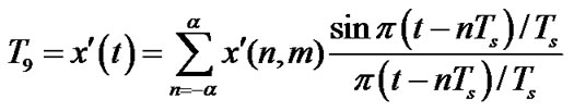 (8)
(8)
The above conversion is performed when sampling of the signal follows the Nyquist sampling theorem.
2.4. Signal Upconversion
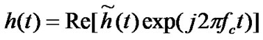
Now, the analog real valued signal  is multiplied by time frequency Kernel exp(j2pfct) to convert it to RF signal from base band. Therefore, the transmitted signal (at T10 in Figure 1) may be given as
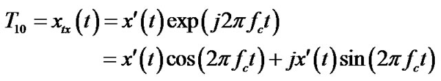 (9)
(9)
3. The Ultra-Wideband Channel Model
The proposed multipath channel model for UWB [2] by IEEE 802.15.3 channel modeling sub-committee is a modified form of indoor channel model proposed by A. Saleh and R. Valenzuela (S-V) [3] that models multipath arrivals in the form of clusters as well as rays within clusters. S-V model clearly distinguishes between ‘cluster arrival rate’ and ‘ray arrival rate’. The cluster arrival rate ‘L’ and ray arrival rate ‘l’ within a cluster is given by Poisson process ( «
«![]() ).
).
Mathematically, the ‘impulse response’ of a channel is given as
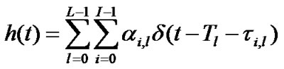 (10)
(10)
where, ai,l = channel coefficient for the i-th ray of the l-th cluster which is log-normally distributed; Tl = delay of the l-th cluster; ti,l = delay of the i-th ray related to the l-th cluster arrival time; t0,l = 0, by definition.
The distribution of cluster arrival time and ray arrival time are given as
p(Tl/Tl-1) = L exp[-L(Tl - Tl-1)], l >0 (11)
p(Tl/Tl-1) = L exp[-L(Tl - Tl-1)] , l >0 (12)
Channel coefficients are defined as
ai,l = pi,l xl bi,l (13)
where, xl = fading associated with cluster; bi,l = fading associated with i-th ray of l-th cluster; pi,l = equiprobable +1/-1 to account for signal inversion due to reflection.
The large bandwidth (7.5GHz) of UWB significantly increases the resolving capability of a UWB receiver. Here, the number of reflections from channel arriving within a short period (0.167nsec. for 6GHz bandwidth and 0.133nsec. for 7.5GHz bandwidth) of impulse is too small. As a result, the central limit theorem is not valid further in UWB systems. Behavior of (averaged) power delay profile is an exponential function of time given as
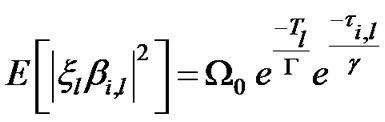 (14)
(14)
where, G = cluster decay factor,  = ray decay factor, W0 = mean energy of the first ray of the first cluster.
However, we shall continue our analysis considering the S-V channel model given by (10) in the next Section.
4. Signal Analysis in an MB-OFDM Receiver
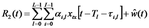
The transmitted signal (9) after passing through a UWB channel is received at the receiver front end given by (at R1 in Figure 2)
 (15)
(15)
where, w(t) = Additive, white, Gaussian noise.
4.1. Preselect Filter
Preselect filter is the very first block of the receiver front end. Here, the out of band signals are attenuated and signals of desired bands are selected. Functionally, this is a wideband band pass filter (BPF). In practice, transfer function of narrow-band band pass filter is given by
 (16)
(16)
where,  is complex impulse response of band pass system given by
 (17)
(17)
wherein, hI & hQ are equivalent LPF coefficients.
The above transfer function of narrow-band BPF is not valid here for UWB. The receiver front end signal passes through BPF with center frequency fc and bandwidth B, which is wider than or equal to the 10dB B.W. of the transmitted signal. For convenience of analysis, we assume that the BPF passes the received desired signal part perfectly without distortion and the filter bandwidth B is equal to an integer multiple of 1/2Tb (Tb = bit duration) such that negligible inter symbol interference and intra symbol interference results. The filtered signal waveform can be expressed (at R2 in Figure 2) as
 (18)
(18)
where  is filtered noise given by [4]
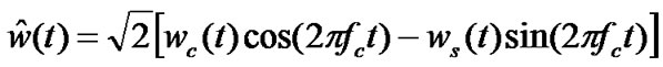 (19)
(19)
wherein, wc(t) and ws(t) are uncorrelated Gaussian random process with the autocorrelation function at the output of BPF given by
 (20)
(20)
Power spectral density of each noise component wc(t) and ws(t) at the BPF output is given by
 (21)
(21)
4.2. Signal Passed through the LNA and Downconverter
The filtered signal is amplified in next step by passing through wideband low noise amplifier with a 3dB flat gain of b. The amplified signal may be given as (at R3 in Figure 2)
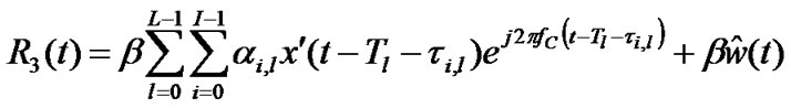
The amplified signal can also be written as
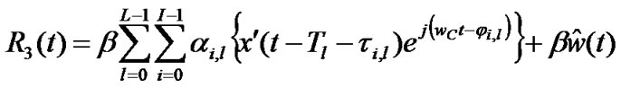
where, ji,l 
 and
and  = delay of i-th ray of l-th cluster measured with respect to the 1st ray of 1st cluster.
Here, ji,l are essentially independent and uniformly distributed over (0, 2p). In MB-OFDM, the OFDM symbol period is =1/Df =242.42nsec. and sample period is 1.89nsec. The maximum delay spread obtained from measurement and supported by simulation for the worst channel here is 25nsec. (CM4). It is to be noted that the phase component j 
 can not be neglected here like narrow-band system as the maximum delay in S-V channel model (25nsec.) is comparable to 2p/wc. For example, 2p/wc= 0.3nsec. (for band 1, with fc=3432MHz) and is 0.09nsec. (for band 3, with fc =3960MHz).
Expanding the above Equation (23) we get,

 (24)
(24)
It is obvious that the phases ji,l are independent (each is a function of its respective path). Assuming that the receiver generates the coherent reference (perfect carrier phase estimate) we get in-phase and q-phase components can be expressed as (at R4 and R5 in Figure 2)

 (25)
(25)

 (26)
(26)
4.3. I-Q Signals at the Low Pass Filter (LPF)Outputs
Both the above down-converted signals after passing through LPFs (which are basically Nyquist filters), give the base band signals expressed as (at R6 and R7 in Figure 2)
 (27)
(27)
 (28)
(28)
where,  and
and
 are Nyquist filtered noise.
4.4. Samples at A/D Converter Output withoutFrequency Offset
Both the above signals are converted in digital domain taking samples at t = nTs given as (at R8 and R9 in Figure 2)
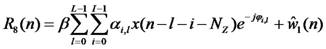 (29)
(29)
 (30)
(30)
The above signal samples obtained at the A/D converter output are basically the same samples fed at the DAC input in the transmitter block.
4.5. ZP Removal and FFT Implementation
In the next step, the ZP is removed by overlapping and add method assuming that the transmitted and received signals are perfectly matched. So, from (29) after ZP removal we get
 (31)
(31)
Next, the N-point FFT is performed to recollect the frequency domain transmitted samples. Now, using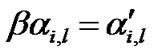 ,
,
 (32)
(32)
 (33)
(33)
It is seen from the above equation that the frequency domain recovered samples are associated with phase errors due to the multipath delay associated with corresponding paths of ray as well as clusters.
4.6. Channel Estimation and Equalization
MB-OFDM channel is estimated from the channel estimate symbols of the preamble. Assuming that the channel is slow fading, its coefficients are considered to be constant during one OFDM symbol. The channel frequency response estimated over one OFDM symbol by the least square estimator is given by
 (34)
(34)
In MB-OFDM, 6 symbols are sent for channel estimation (CE) purpose. Hence final estimated channel frequency response can be obtained by taking the average of estimated channel coefficients over CE symbols available per band (Cb).
 (35)
(35)
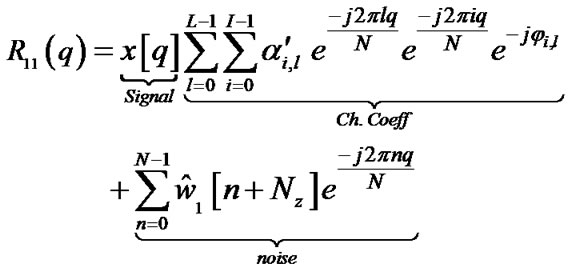
In the above explanation it is clearly vivid that the error in channel estimates i.e. the distortion coming due the addition of noise in path (second part of Equation (34)) and the comparable multi path delay with respect to 2p/wc reflected as  in the first term of Equation (34). Equalization of data OFDM symbols is done by using one tap equalizer, and hence estimated received samples are given by
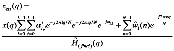
where, q = 0, 1, 2, ……………. 128.
4.7. QPSK Demodulation and Detection
The estimated samples xest(q) are fed to QPSK demodulator. At the output of the demodulator the transmitted symbol is recovered back taking decision over the signed amplitude of the xest(q). The QPSK demodulator input symbol xest(q) can be represented as
 (37)
(37)
5. Signal Analysis in Receiver with Carrier Frequency Offset Correction and CRLB Calculation
Let the normalized carrier frequency offset is expressed in terms of sub carrier spacing f as , where,
  is the carrier frequency offset. After removal of ZP (32 samples) the signal obtained at the receiver with frequency offset is given by

After FFT, the signal is presented as
 (39)
(39)
It is observable from Equation (39) that that the performance fall gradually increases with FO (Δfb) when <
< while it results in a complete detection error when
 . In Equation (38) it is observed that f¢ causes a phase rotation of
 . If it remains uncorrected, it causes both rotation of QPSK constellation points and a spread of the constellation points.
Frequency offset synchronization may be performed in receiver in time domain before performing FFT of the incoming signal either by cyclic extension or by using special training symbols. Synchronization technique based on cyclic extension is not suitable for high rate packet transmission (like MB-OFDM) because - (i) An accurate synchronization needs an averaging over large (>10) nos. of OFDM symbols to attain distinct number of peaks and a reasonable SNR. (ii) For efficient data transmission, synchronization time needs to be as short as possible. In Training symbol based synchronization technique, the incoming signal is correlated with the complex conjugate of the known training signal. From the correlation peaks in the matched filter output signal, symbol frequency offset can be estimated. We continue our analysis with a time domain frequency offset estimation scheme proposed in [5]. Now, considering
 (40)
(40)
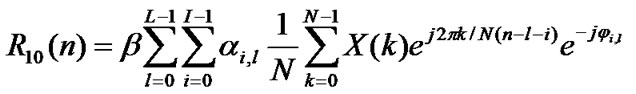
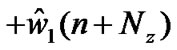
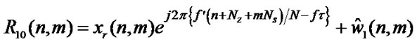
The received signal R10(n) for the n-th sample of the m-th OFDM symbol (0 ≤ m ≤ Z-1) can be expressed as
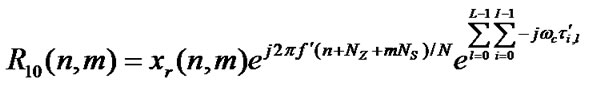
 (41)
(41)
Now, considering 
 (42)
(42)
where,  is the AWGN added with the n-th sample of m-th OFDM symbol. Based on (42), the n-th sample of m+1-th OFDM symbol can be given as

 (43)
(43)
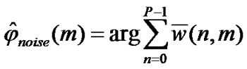
The phase difference between n-th sub-carriers of 2 consecutive OFDM symbols m & (m+1) is 2p{(f¢NS)/N}. Phase offset between 2 consecutive OFDM symbol is obtained by complex conjugate multiplication of n-th samples of m-th OFDM symbol & (m+1)-th OFDM symbol. So,

where,
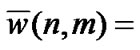

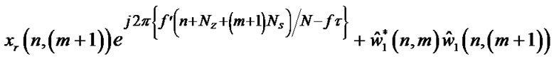 (45)
(45)
For preamble, same OFDM symbol is repeated 21 times to constitute the training sequence utilized for synchronization. The frame format is shown in Figure 3. Hence typically,
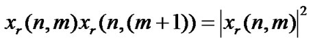 (46)
(46)
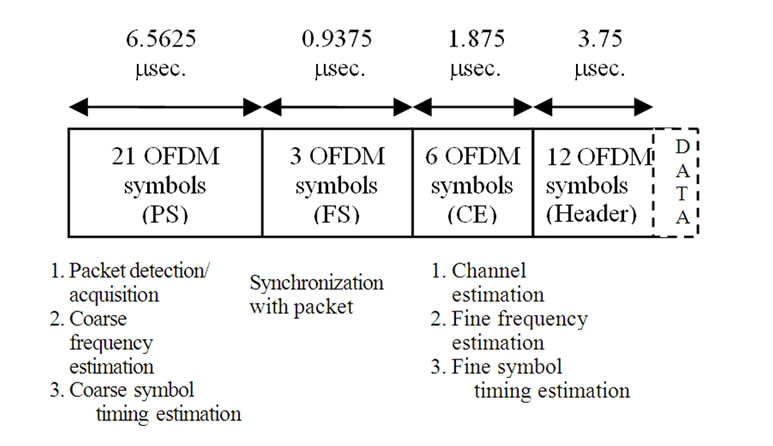
Figure 3. MB-OFDM frame format.
Estimated frequency offset from P number of sample pairs of m-th & (m+1) - th OFDM symbols,
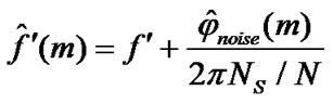 (47)
(47)
where,
 (48)
(48)
The n-th noise sample of m-th OFDM symbol is Gaussian distributed with zero mean. The variance of estimated frequency offset from two successively received OFDM symbols can be easily given as
 (49)
(49)
Now, If we continue this offset estimation over ‘L’
OFDM symbols, comparison will be caused for (L – 1) times.
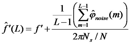 (50)
(50)
Correspondingly, the variance calculated,
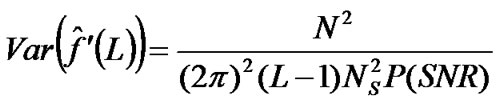 (51)
(51)
5.1. CRLB for Estimated Frequency Offset
The expression for n-th pair of m-th and (m+1)-th OFDM symbols can also be written from Equation (43) as
 (52)
(52)
where,  ,
,  ,
, and
and  are the in-phase and q-phase components of the effective noise of the complex conjugate product
  respectively obtained from (43).
Now, let us take
 (53)
(53)
 (54)
(54)
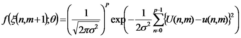
Expressing , the probability density function of the sample vector
  (when unknown parameter vector is q ) is given by
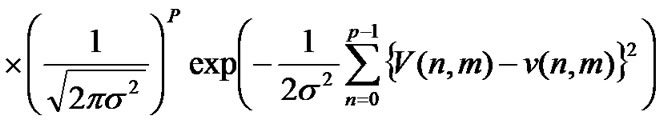
Inverse of Fisher Information Matrix gives the variance of unknown parameter estimates. Unbiased Cramer Rao Lower Bound (CRLB) of estimations obtained from diagonal elements of Inverse Fisher Information Matrix I(q ) [6] is as
 (56)
(56)
when frequency offset estimation is carried over ‘L’ OFDM symbols, the variance is
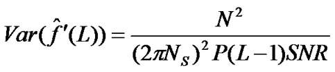 (57)
(57)
where SNR = signal to noise ratio.
6. Simulation Results and Discussions
Simulation is carried out to study the performance of MB-OFDM systems with frequency offset correction using Time Frequency Interleaved (TFI) pattern 1 [1] under UWB channel model CM4 and AWGN. Relevant parameters from ECMA-368 standard for MB-OFDM are considered for the simulation study. We have considered 1000 noisy realizations in each of the 100 UWB channels for our simulation. We estimated the channel using Least Square (LS) estimate during channel estimation sequence (25th-30th OFDM symbol of the frame format) of the preamble.
Coarse frequency offset of the frequency offset estimation scheme [5] is estimated for an AWGN channel using several consecutive OFDM symbols (L = 2, 3 4, 5, and 6) in the preamble for MB-OFDM systems. Figure 4 shows change of variance of the frequency offset estimation error of our scheme vs. SNR for various values of L, viz. 2, and 6. As expected, the variance of frequency offset estimation error decreases with increase in L. However, a lower value of L is desirable in practice to reduce the system computational complexity. Figure 4 also includes the error variance of frequency offset estimate and the CRLB of the error variance for our scheme for L=2 and 6. It is observed that the error variance as per our scheme is very close to the respective CRLB.
Figure 5 presents the BER vs. Eb/N0 plots for our scheme with L = 2, 3, and 6 in UWB channel CM4 for normalized frequency offset of 0.05. It is observed that, for CM4, Eb/N0 improves by 8.3dB and 3.6dB with L = 6 compared to L = 2 and L = 3 respectively for BER=10-4 [5].
7. Conclusions
To make UWB receiver design techno-economically challenging, understanding of the key aspects of different signal processing stages in an UWB transceiver system is very essential.

Figure 4. Variance of frequency offset estimation error: a) CRLB calculated with L=6; b) simulation with L=6; c) CRLB calculated with L=2; d) simulation with L=2 in AWGN channel.
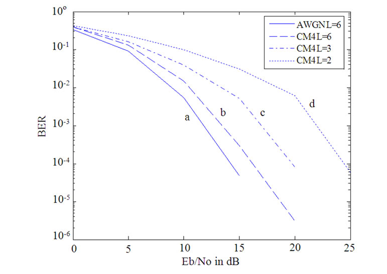
Figure 5. BER vs. Eb/No for: a) AWGN with L=6; b) CM4 with L=6; c) CM4 with L=3 and d) CM4 with L=2.
Considering this, in this work, we have mathematically analyzed the propagation of signal in an MB-OFDM based UWB transceiver system under realistic channel environment. This mathematical analysis is further extended to investigate the effects of synchronization imperfections due to carrier frequency offset in the receiver. The estimation of this frequency offset is carried out following our earlier proposed algorithm [5]. The Cramer Rao Lower Bound of the variance of estimation error is calculated and compared with the computer simulation. Closeness of both the curves as depicted by the graphical representation proves the effectiveness of our estimation algorithm for UWB receivers. A considerable improvement in system performance with higher number of iterations of the estimation algorithm is also reported. However, a higher number of iteration increases the receiver complexity. In practice, a compromise between performance improvement and receiver complexity is essential for effective receiver design.
The significance of this work is to show the fundamental differences of UWB signal processing in comparison with narrow-band system design which is being reported for the first time in literature here to the best of our knowledge. We further believe that, the detailing of the crucial aspects of UWB signal propagation discussed here will help the researchers to develop a clear understanding of this promising technology.
The frequency offset estimation algorithm discussed in this paper can be used in developing the practical UWB receiver. This mathematical frame-work can further be extended for timing imperfection scenario.
8. References
[1] ECMA-368, “High rate ultra wideband PHY and MAC standard,” 2nd Edition, December 2007, available at: http://www.ecma-international.org/publications/standards/Ecma-368.htm
[2] J. Foerster, “Channel modeling sub-committee report final,” IEEE, Document IEEE P802.15-02/490r1-SG3a, February 2003.
[3] A. A. M. Saleh and R.A. Valenzuela, “A statistical model for indoor multipath propagation,” IEEE Journal on Selected Areas in Communications, Vol. 5, pp. 128–137, February 1987.
[4] M. K. Simon, S. M. Hinedi, and N. C. Lindsey, “Digital communication techniques signal design and detection,” Prentice Hall PTR, 2003.
[5] D. Sen, S. Chakrabarti, and R. V. Raja Kumar, “An efficient frequency offset estimation scheme for multiband OFDM ultra-wideband systems,” IEEE VTC-2008- Spring, Singapore, pp. 973–977, May 11–14, 2008.
[6] S. M. Kay, “Fundamentals of statistical signal processing: Estimation theory,” Prentice Hall PTR, 1993.