Vol.1, No.3, 229-233 (2009)
doi:10.4236/ns.2009.13031
SciRes Copyright © 2009 Openly accessible at http://www.scirp.org/journal/NS/
Natural Science
Focal shift of radially polarized bessel-modulated
gaussian beam by phase shifting
Xiu-Min Gao1,2, Ming-Yu Gao1, Song Hu1, Han-Ming Guo2, Jian Wang1, Song-Lin Zhuang2
1Electronics & Information College, Hangzhou Dianzi University, Hangzhou, China; xiumin_gao@yahoo.com.cn
2Optics & Electronics College, University of shanghai for Science and Technology, Shanghai, China
Received 28 September 2009; revised 23 October 2009; accepted 26 October 2009.
ABSTRACT
Focal shift of radially polarized Bessel-modu-
lated Gaussian (QBG) beam by phase shifting is
investigated theoretically by vector diffraction
theory. The phase shifting distribution is the
function of the radial coordinate. Calculation
results show that intensity distribution in focal
region can be altered considerably by the topo-
logical charge of QBG beam and the phase pa-
rameter that indicates the vary degree of the
phase shifting along radial coordinate. Topolo-
gical charge induces the focal shift in trans-
verse direction, while phase parameter leads to
the focal shift along optical axis of the focusing
system. More interesting, the focal shift may be
incontinuous in certain case.
Keywords: Focal Shift; Bessel-Modulated
Gaussian Beam; Vector Diffraction Theory
1. INTRODUCTION
Since Caron and Potvliege introduced a novel class of
beam expressed in cylindrical coordinate system re-
cently, namely, the Bessel-modulated Gaussian beams
with quadratic radial dependence (QBG beam) [1],
QBG beam has attracted much attention [2-7]. It was
shown that such class of beams has familiar collinear
geometry of the Gaussian beam and also an interesting
non-Gaussian features for certain values of its parame-
ters [1-3]. Belafhal and Dalil-Essakali studied the pro-
pagation properties of QBG beams through a unaper-
tured optical paraxial ABCD system [4]. X. Wang, and
B. Lü researched on the beam propagation factor
(M2-factor), far-field distribution, and the kurtosis pa-
rameter of such type of beams [3,5,6]. And the Bes-
sel-modulated Gaussian light beams passing through a
paraxial ABCD optical system with an annular aperture
has also been studied [7]. On the other hand, in the
investigation of the focusing properties of optical
beams, tracing the movement of the point of absolute
maximum intensity along optical axis has attracted
many researchers for several decades [8-12]. It was
found that the point of absolute maximum intensity
does not coincide with the geometrical focus but shifts
along optical axis. This phenomenon is referred to as
focal shift. More interesting, the focal shift may be
incontinuous in certain optical focusing systems.
Almost all QBG beams in above previous papers are
in scalar a form, which means the polarization property
of optical field is not considered. In fact, the polariza-
tion is very important characteristics to alter propagat-
ing and focusing properties of beams. For example,
laser beam with cylindrical symmetrical polarization
have attracted many researchers recently because the
electric field in focal region of such cylindrical vector
beam has some unique properties [13-16]. The present
paper is aimed at studying focal shift of radially polar-
ized QBG beam by vector diffraction theory. The prin-
ciple of the focusing radially polarized QBG beam with
phase shifting is given in Section 2. Section 3 shows
the simulation results and discussions. The conclusions
are summarized in Section 4.
2. PRINCIPLE OF THE FOCUSING
RADIALLY POLARIZED QBG BEAM
WITH PHASE SHIFTING
In the focusing system we investigated, focusing beam is
radially polarized QBG beam whose value of transverse
optical field is same as that of the scalar QBG [1-3], and
its polarization distribution turns on radially symmetric
[13,14]. Therefore, in the cylindrical coordinate system
 
,,0r
the field distribution
E
f the radially
polarized QBG beam at the plane is written as,
o,,0r

00
,,0,,0 r
ErEr n

 
(1)
where r
n
is the radial unit vector of polarized direction.
Term
 
,,0
Er
is optical field value distribution and
can be written in the from [1-5],
230 X. M. Gao et al. / Natural Science 1 (2009) 229-233
SciRes Copyright © 2009 Openly accessible at http://www.scirp.org/journal/NS/

22
0222
00
,,0exp exp
m
rr
Er BJim


 

 (2)
where 2m
J
denotes the Bessel function of order |m|/2,
m is the topological charge of QBG beam, ω0 is the
waist width of the Gaussian beam, and μ is a beam pa-
rameter which is complex-valued in general. B is a con-
stant. According to vector diffraction, the electric field in
focal region of radially polarized QBG beam is [17],

,,Ez

z
z
EeEe Ee
 


(3)
where e
, e
, and
z
e
are the unit vectors in the radial,
azimuthal, and propagating directions, respectively. To
indicate the position in image space, cylindrical coordi-
nates with origin

,,z0z
 located at the
paraxial focus are employed. Eρ, Ez, and EΦ are ampli-
tudes of the three orthogonal components and can be
expressed as.

2
0
00
,, cos
iA
Ez E

 


sincos cos




expcossin cosikzd d



(4)

2
0
00
,, cos
iA
Ez

 

 E
sin cos sin




d d
expcossin cosik z
 

 


(5)

22
0
00
,,cos sin
Z
iA
Ez E





expcossin cosikzd d



(6)
where θ and φ denote the tangential angle with respect to
the z axis and the azimuthal angle with respect to the
x
axis, respectively. k is wave number. α=arcsin(NA) is
convergence angle corresponding to the radius of inci-
dent optical aperture. In order to make focusing proper-
ties clear and simplify calculation process, after simple
derivation, Eq.2 can be rewritten as,

0,,0E


2
222
sin
m
BJ
wNA

 



2
22
sin
expexp im
wNA

 


 (7)
where 00 rw
is called relative waist width. The
phase shifting of the radially polarized QBG beam is the
function of radial coordinate and is in the from as,
tan
cos tan
C
 

(8)
where C is phase parameter that indicates the vary de-
gree of the phase shifting along radial coordinate. Sub-
stitute the Eq.7 and Eq.8 into Eqs.4-6, we can obtain,

2
00
, ,cossincos
iAB
Ez





  
22
222 22
sin sin
cos exp
m
J
wNA wNA







 
tan
expexpexpcos tan
iimiC



 



expcossin cosikzd d



(9)

2
00
,,cossin cos
iAB
Ez





sin

22
222 22
sin sin
exp
m
J
wNA wNA






 
tan
expexpexpcos tan
iimiC


 



expcossin cosikzd d



(10)
 
22
00
,,cos sinexp
Z
iAB
Ez i




  
22
222 22
sin sin
exp exp
m
J
im
wNA wNA

 

 

 
 
tan
expcos tan
iC

 



expcossin cosikzd d



(11)
The optical intensity in focal region is proportional to
the modulus square of Eq.3. Basing on the above equa-
tions, focusing properties of radially polarized QBG
beam with phase shifting can be investigated theoreti-
cally.
3. RESULTS AND DISCUSSIONS
Without of loss of validity and generality, it was sup-
posed that NA=0.95, μ=5 and w=1. Firstly, the intensity
distributions in focal region of the radially polarized
QBG beam with phase shifting are calculated under
condition of m=0 and different C, and are illustrated in
Figure 1. It should be noted that the distance unit in all
figures in this paper is k-1, where k is the wave number
of incident beam. In addition, the coordinates are the
radial distance and axial distance, and symmetric char-
acteristics should be paid attention to when see figures.
It can be seen that there occurs one dark hollow focus in
focal region for C=0.0. Dark hollow focus refers to those
focuses whose optical intensity is weaker than that
around it and is stable optical trap for those particles
X. M. Gao et al. / Natural Science 1 (2009) 229-233 231
SciRes Copyright © 2009 http://www.scirp.org/journal/NS/
whose refractive index is smaller than that of surround-
ing media, and this condition is very common, especially
in life science optical trapping systems, so construction
of dark focal spot is very important and attracts many
researchers [18,19]. Therefore, radially polarized QBG
beam can be used to construct dark hollow focus. On
increasing C, this dark hollow focus shifts along optical
axis away from the optical aperture of the focusing syst-
em, as shown in Figure 1b. And the point of absolute
maximum intensity also shifts along optical axis. The
number of the absolute maximum intensity changes from
two to one, namely, the on-axis intensity peak near to the
optical aperture weakens on increasing C, as illustrated
in Figure 1c. Increase C continuously, the shape of dark
hollow focus goes on shifting along optical axis. How
ever, the position of absolute maximum intensity becomes
incontinuous, namely, jumps to one position near the
optical aperture, and then also shifts far away from opti-
cal aperture.
In order to understand the focal shift deeply, the de-
pendence of focal shift on C is calculated and shown in
(a) (b)
(c) (d)
(e) (f)
Figure 1. Intensity distributions in focal region for m=0 and (a) C=0.0, (b) C=0.3, (c) C=0.6, (d) C=0.9, (e) C=1.2, and
(f) C=1.5, respectively
Openly accessible at
X. M. Gao et al. / Natural Science 1 (2009) 229-233
SciRes Copyright © 2009 Openly accessible at http://www.scirp.org/journal/NS/
232
Figure 2. It can be seen from this figure that when
C=0.0 there are two absolute maximum intensity peaks
on axis, and on increasing C, one absolute maximum
intensity peaks weakens so that there is only one abso-
lute maximum intensity peak, and in the focal evolution
process, the distance of focal shift increases on increas-
ing C.
When C changes from 1.2 to 1.3, the position of ab-
solute maximum intensity peak jumps from on position
to another position, then also shifts increases on increas-
ing C. Focal shift is incontinuous.
Figure 3 illustrates the optical intensity distributions
in focal region under condition of m=2 and different C.
Figure 2. Dependence of focal shift on
C for m=0.
(a) (b)
(c) (d)
Figure 3. Intensity distributions in focal region for m=2 and (a) C=0.0; (b) C=0.3; (c) C=0.6, and; (d) C=1.5, re-
spectively.
(a) (b)
Figure 4. Intensity distributions in focal region for m=7 and (a) C=0.0; (b) C=1.5, respectively.
X. M. Gao et al. / Natural Science 1 (2009) 229-233
SciRes Copyright © 2009 Openly accessible at http://www.scirp.org/journal/NS/
233
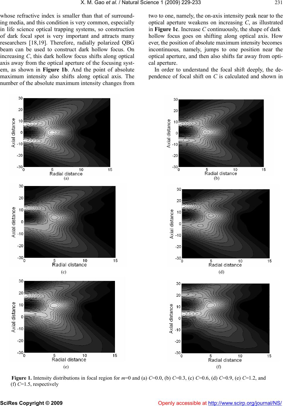
For C =0.0, there is two overlapping intensity rings in
focal region, as shown in Figure 3a. On increasing C.
one of these two intensity ring weakens, so that one fo-
cal ring comes into being and shifts in axial direction.
From all above focal pattern evolution, we can see that
Topological charge induces the focal shift in transverse
direction, while phase parameter leads to the focal shift
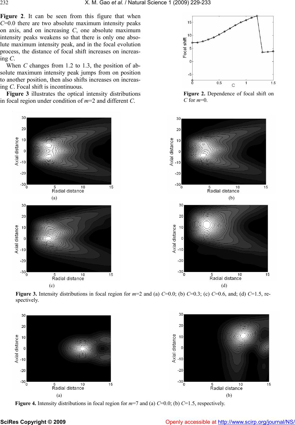
along optical axis of the focusing system. In order to
show this point, optical intensity distributions in focal
region under condition of m=7 are also calculated and
illustrated in Figure 4. Ring intensity distribution can be
used to construct a ring optical trap that is stable for
those particles in focal region whose refraction index is
bigger than that of their surrounding medium.
4. CONCLUSIONS
Focal shift of radially polarized QBG beam by phase
shifting is investigated theoretically by vector diffraction
theory in this paper. The phase shifting distribution is the
function of the radial coordinate. Simulations results
show that intensity distribution in focal region can be
altered considerably by the topological charge of QBG
beam and the phase parameter that indicates the vary
degree of the phase shifting along radial coordinate.
Dark hollow focus can be obtained in focal region of
radially polarized QBG beam, which is very desirable in
optical tweezers technique. Particularly, topological
charge induces the focal pattern evolution in transverse
direction, while phase parameter leads to the focal shift
along optical axis more significantly.
5. ACKNOWLEDGMENT
This work was supported by National Basic Research
Program of China (2005CB724304), National Natural
Science Foundation of China (60708002, 60777045,
60871088, 60778022), China Postdoctoral Science
Foundation (20080430086), and Shanghai Postdoctoral
Science Foundation of China (08R214141).
REFERENCES
[1] C. F. R. Caron and R. M. Potvliege, (1999)
Bessel-modulated Gausian beams with quadratic radial
dependence. Opt. Commun, 164, 83-93.
[2] Z. Hricha and A. Belafhal, (2005) Focal shift in the
axisymmetric Bessel-modulated Gaussian beam. Opt.
Commun, 255, 235-240.
[3] X. Wang and B. Lü, (2002) The beam propagation factor
and far-field distribution of Bessel-modulated Gaussian
beams. Opt. Quant. Electron, 34, 1071-1077.
[4] A. Belafhal and L. Dalil-Essakali, (2000) Collins formula
and propagation of Bessel-modulated Gaussian light
beams through an ABCD optical system. Opt. Commun,
177, 181-188.
[5] X. Wang and B. Lü, (2003) The beamwidth of Bessel-
modulated Gaussian beams. J. Mod. Opt, 50, 2107-2115.
[6] B. Lü and X. Wang, (2002) Kurtosis parameter of
Bessel-modulated Gaussian beams propagating through
ABCD optical systems. Opt. Commun, 204, 91-97.
[7] Z. Mei, D. Zhao, X. Wei, F. Jing, and Q. Zhu, (2005)
Propagation of Bessel-modulated Gaussian beams
through a paraxial ABCD optical system with an annular
aperture. Optik, 116, 521-526.
[8] Y. Li and E. Wolf, (1981) Focal shifts in diffracted
converging spherical waves. Opt. Commun, 39, 211-215.
[9] M. M. Corral, M. T. Caballero, L. M. Escriva, and P.
Andres, (2001) Focal-shift formula in apodized non-
telecentric focusing systems. Opt. Lett, 26, 1501- 1503.
[10] C. J. R. Sheppard and P. Tötök, (2003) Focal shift and
axial coordinate for high-aperture systems of finite
Fresnel number. J. Opt. Soc. Am. A, 20, 2156-2162.
[11] X. Gao, F. Zhou, W. Xu, and F. Gan, (2005) Gradient
force pattern, focal shift, and focal switch in an apodized
optical system. Optik, 116, 99-106.
[12] X. Gao and J. Li, (2007) Focal shift of apodized
truncated hperbolic-Cosine-Gaussian beam. Opt. Com-
mun, 273, 21-27.
[13] K. S. Youngworth and T. G. Brown, (2000) Focusing of
high numerical aperture cylindrical-vector beams. Optics
Express, 7, 77-87.
[14] Q. Zhan, (2009) Cylindrical vector beams: from mathe-
matical concepts to applications. Advances in Optics and
Photonics, 1, 1–57.
[15] X. Gao, S. Hu, H. Gu, and J. Wang, (2009) Focal shift of
three-portion concentric piecewise cylindrical vector
beam. Optik, 120, 519-523.
[16] F. Lu, W. Zheng, and Z. Huang, (2009) Coherent anti-
stokes Raman scattering micriscopy using tighly focused
radially polarized light. Opt. Lett, 34, 1870-1871.
[17] S. Sato and Y. Kozawa, (2009) Hollow vortex beams. J.
Opt. Soc. Am. A, 26, 142-146.
[18] J. Arlt and M. J. Padgett, (2000) Generation of a beam
with a dark focus surrounded by regions of higher
intensity: The optical bottle beam. Opt. Lett, 25, 191-
193.
[19] D. Ganic, X. Gan, M. Gu, M. Hain, S. Somalingam, S.
Stankovic, and T. Tschudi, (2002) Generation of dough-
nut laser beams by use of a liquid-crystal cell with a
conversion efficiency near 100%. Opt. Lett, 27, 1351-
1353.