Natural Science
Vol.4 No.8A(2012), Article ID:21653,10 pages DOI:10.4236/ns.2012.428088
New strategy for controlling structures collapse against earthquakes
![]()
Department of Civil Infrastructure Works, Faculty of Technological Application, Technological Educational Institution of Athens, Athens, Greece; nikos_pnevmatikos@hotmail.com
Received 12 May 2012; revised 15 June 2012; accepted 30 June 2012
Keywords: Structural Control; Dynamic Control Strategy; Structural Dynamics; Earthquake Engineering
ABSTRACT
A control strategy for structures subjected to earthquake actions is investigated. The strategy is inspired by the human beings’ reaction when they are attacked by earthquake excitation. Humans realize the earthquake excitation by the neurons, sent this information to the brain, a decision is taken there and by neuron system the decision is sent back to the muscles for a suitable action. In similar way, the control strategy consists of monitoring the incoming signal, analyzing it and recognizing its dynamic characteristics, applying the control algorithm for the calculation of the required action, and, finally, applying this action. Thus, the way in which the structure is controlled, and the algorithm that is used, are based on the dynamic characteristics and the frequency content of the applied earthquake signal. The algorithm transforms the earthquake signal and structure into a complex plane and, depending on their relative positions, the equivalent forces that should be applied to the structure by the control devices, which are installed on the building, are calculated. From the numerical results it is shown that the above control procedure is efficient in reducing the response of building structures subjected to earthquake loading, with small amount of required control forces. The influence of time delay and saturation capacity is taken into account. Characteristic buildings controlled by pole placement algorithm and subjected to earthquake excitation are analyzed for a range of levels of time delay and saturation capacity of the control devices. The response reduction surfaces for the combined influence of time delay and force saturation of the controlled buildings are obtained. Conclusions regarding the choice of the control system and the desired properties of the control devices are drawn.
1. INTRODUCTION
Innovative means of enhancing structural functionality and safety against natural and manmade hazards are currently in various stages of research and development. They can be grouped into the following broad areas: passive control systems and active, semi active, or hybrid control systems. Active, semi active, and hybrid control systems are a natural evolution of passive control technologies. The use of active, semi-active and the combination of passive, active or semi-active systems as a means to protect the structures against seismic loads has received considerable attention in the last few decades. The devices of this category are part of an intergrated system, with real time processing controllers (control algorithms) and sensors, all installed to the structure. They act simultaneously with the excitation to provide enhanced structural behavior for improved service and safety.
Over the past few decades various control algorithms and control devices have been developed, modified and investigated by various groups of researchers. In the work of Yao [1] the concepts of structural control are presented. Yang et al. [2-7] introduced control algorithms for semi active stiffness devices, proposed optimal control theory for structures and developed the sliding mode control. Other researchers like Soong [8], and Housner [9] gives an overview of the control methods, practice, and applications in the structural systems. Spencer et al. [10, 11] developed a magnetoreological damper as a control device for structure. Symans and kostantinou [12,13] performed seismic testing of a building structure with semi-active fluid damper. Experimental study on active variable stiffness system have been done by Kobori [14, 15]. Kurata [16] investigated the reliability of applied semi-active to structures.
While many of these structural control strategies have been successfully applied, challenges pertaining to cost, reliance on external power and mechanical intricacy during the life of the structure have delayed their widespread use. In this paper the well known from literature pole placement algorithm is used but is extended taking into account the influence of time delay variation and saturation capacity of the control device.
2. CONTROL STRATEGY OF STRUCTURES
The structural controlled strategy is inspired from the human beings reaction to earthquake excitation. As humans realize the earthquake excitation by the neurons and sent this information to the brain, a sensor located at the base of structures detects the motion and sent this information to a computer. Then, brain takes a decision and by neuron system the decision is sent back to the muscles for suitable action, in similar way in the structure, the control algorithm the equivalent force and by sensors this information is sent back to the devices which are locate in to the structure for suitable action. This similarity is shown in Figure 1.
The general control strategy consists of the following stages: 1) the monitoring of the incoming signal, 2) its FFT or wavelet analysis for recognition of its dynamic characteristics, 3) the selection of poles of the integrated controlled system, 4) the application of the pole placement algorithm for the calculation of the required actions, and finally, 5) accounting for the limitations of the devices that are used, the application of these actions, considering saturation effects and time delay. A flow chart of this integrated control strategy is shown in Figure 2.
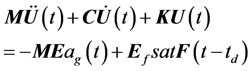
The equation of motion of a controlled structural system with n degrees of freedom ui, subjected to an earthquake excitation ag, is given by Eq.1.
 (1)
(1)
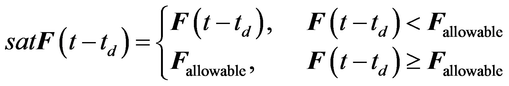
where M, C, K denote the mass, damping and stiffness matrices of the structure, respectively, E, Ef are the location matrix for the earthquake and the control forces on the structure, and satF is the saturated control force matrix, which is applied to the structure with time delay td and is given by:
 (2)
(2)
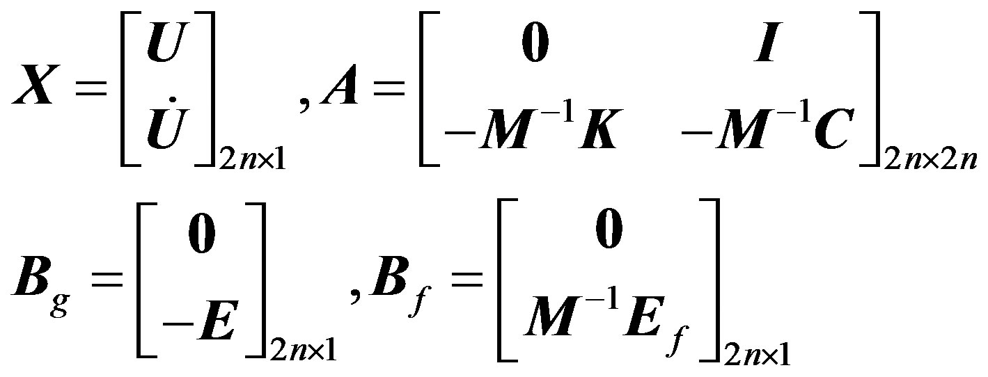
Fallowable is the maximum capacity of the control device. In the state space approach the above Eq.1 can be written as follows:
 (3)
(3)
The matrixes X, A, Bg, Bf are given by:
 (4)
(4)
The matrixes Υ, C, Df, Dg, and v are the output states, the output matrix, the feed forward control force matrix, the excitation matrix and the noise matrix, respectively. We consider the case where the output variables are the same as the states of the system and there is no application of the control forces to the output variables, so the matrixes C, D are the identity and zero matrix, respecttively.
The eigenvalues or poles of the uncontrolled system are given by:
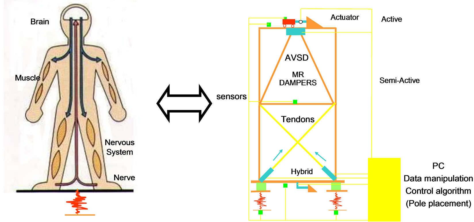
Figure 1. Similarities between Human being reactions to earthquake excitation and structural controlled.
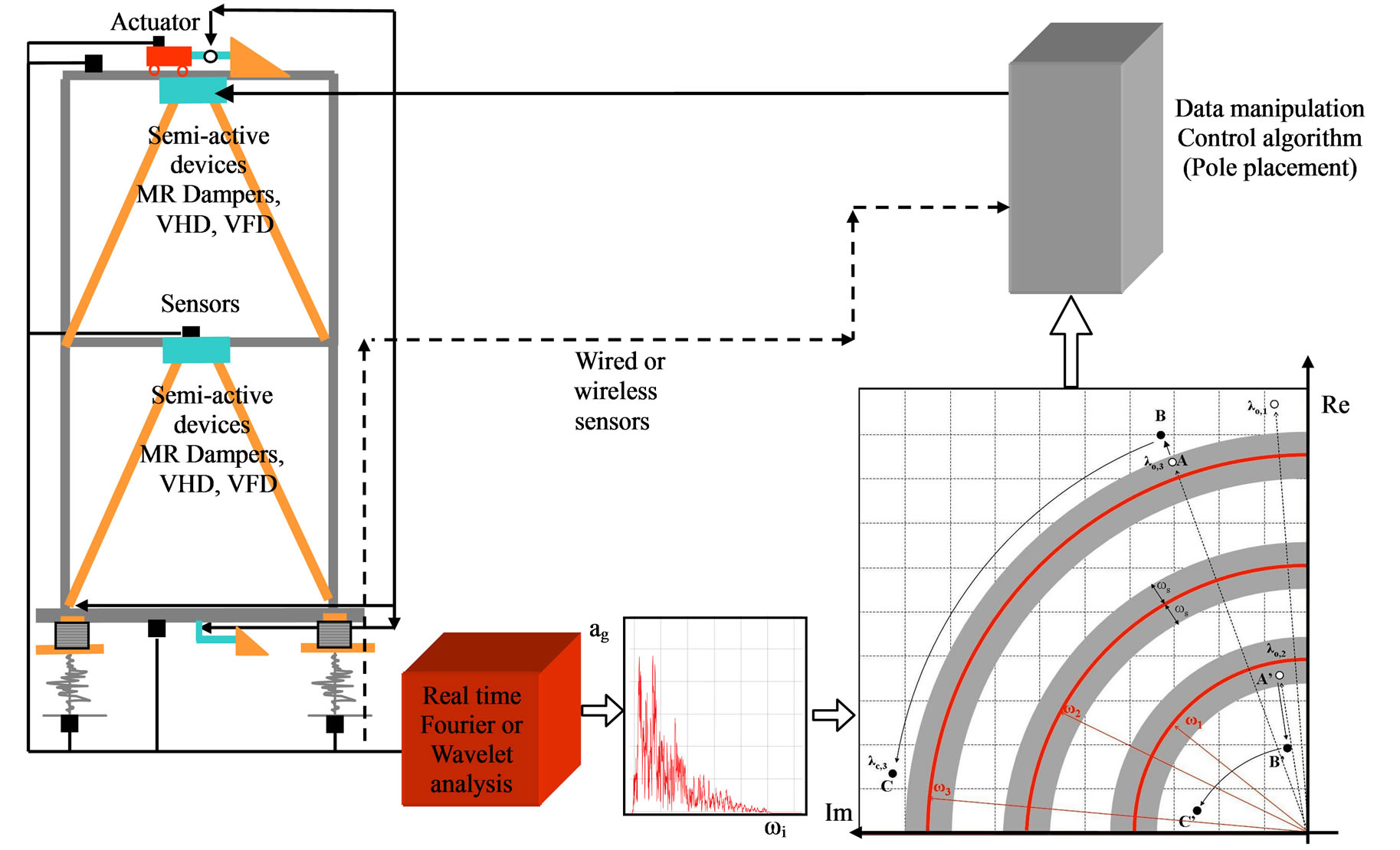
Figure 2. The general flow chart of the proposed control strategy.
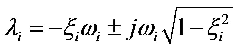 (5)
(5)
where ωi and ξi are the eigenfrequencies and the damping ratio, respectively, which are obtained from the solution of the eigenvalue problem. If a state space formulation is adopted, then these eigenvalues are obtained directly from the eigenvalues of matrix A:
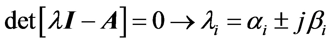 (6)
(6)
The representation of the poles in the complex plane is shown in Figure 3.
It is assumed that the control force F is determined by linear state feedback:
 (7)
(7)
G is the gain matrix, which will be calculated according to the desired poles of the controlled system.
The control of structures causes changes of their stiffness or damping and, consequently, their dynamic characteristics, in a direct or indirect way, depending on the device we use. The question is how to estimate the control force or the matrix G in such a way, that we can achieve the desired dynamic characteristics for the controlled structure. In this paper the well known pole placement algorithm is used to estimate the feedback
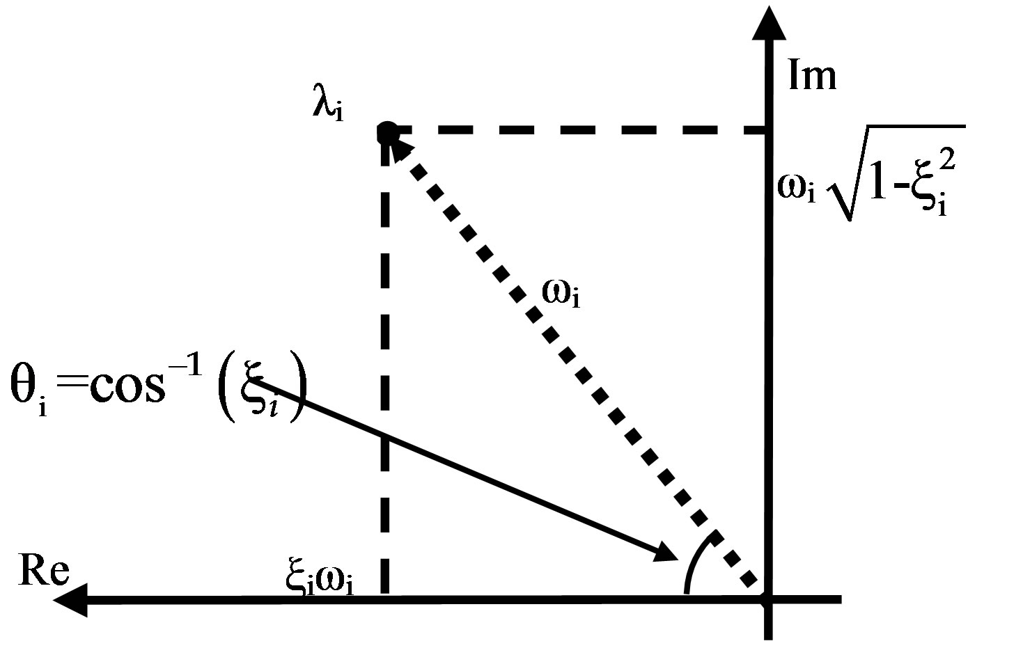
Figure 3. Representation of the poles of the structure in the complex plane.
matrix G. In the application of pole placement one should assume the desired location for the poles of the controlled system, and then continue with the application of the algorithm. The successful application of the algorithm requires judicious placement of the closed loop eigenvalues.
The selection of the position of the eigenvalues (poles) of the controlled system is suggested in work of Pnevmatikos and Gantes [17]. Except of the location of the poles another two importance practical issues, time delay, td, and saturation effect, satF, are examined.
In order to simulate numerical the control strategy, a program in MATLAB has been developed. The main files, their function and the simulink model are shown in Figure 4. The time delay and saturation capacity, were also included in the simulink model of MatLab software as shown in Figure 4.
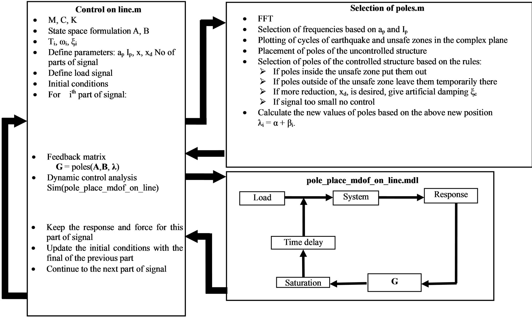
Figure 4. The main files, their function and the simulink model of MATLAB program.
The novelty of the proposed controlled procedure is that provides an integrated tool accounting for time delay of system and saturation of controlled force, based on the device capacity, acting simultaneously and not separately as in the conventional methods. Also the poles of the controlled system are estimated based on the dynamic characteristic of incoming earthquake and are not constant throughout the life of the controlled structure. To examine the efficiency of the proposed control strategy this program has been applied to single and multi degree of freedom systems subjected to harmonic and earthquake excitations.
3. EXAMPLES AND NUMERICAL EXPERIMENTS
The above dynamic control strategy has been applied to one single, one three and one eight degree-of-freedom system, modeling buildings with the properties shown in Figure 5. The three story building model has been studied by Kobori and Kamagata 1992, while the eight story building is described in the work of Yang et al. 2000. The systems have been subjected to ten earthquake records as well as to sinusoidal and pulse dynamic excitations, all scaled at 0.3 g.
Each signal was recorded on line and data at 1 sec time intervals were processed by Fourier analysis. Even though the choice of poles was based on the above mentioned time division and the feedback time was about 1 sec, no stability problems were observed during the simulation procedure. For constant time delay 30 ms and saturation capacity for all devices equal to 1000 kN the response of controlled and uncontrolled structure and demanded force for each floor of the three-story building subjected to Kalamata (1986) earthquake is shown in Figures 6 and 7 respectively. From the analysis results it is shown that the relative displacements are reduced by 65% to 100% compared to the uncontrolled ones depending how many control devices are used. The total acceleration is also reduced by 45% to 95% in the case where the number of control devises is equal to the number of degrees of freedom. This percentage changes in the case of the three story building with one control force and becomes 10% to 60%. For the eight story building with five control devices reduction between 10% and 60% is observed, while for the three control devices the reduction is negligible.
In general, when the control devices are equal to the number of degrees of freedom, the structure tends to perform a rigid body motion. As the number of control devices is reduced this motion changes and relative displacements between the floors are observed.
In real control systems, time delay and saturation of control force capacity exist simultaneously and influence each other. Simulations have been performed for a wide range of values of those two parameters and the ratio of the maximum response of the controlled system, umax,con, to the maximum response of the uncontrolled one, umax, was obtained. The results of those simulations for the
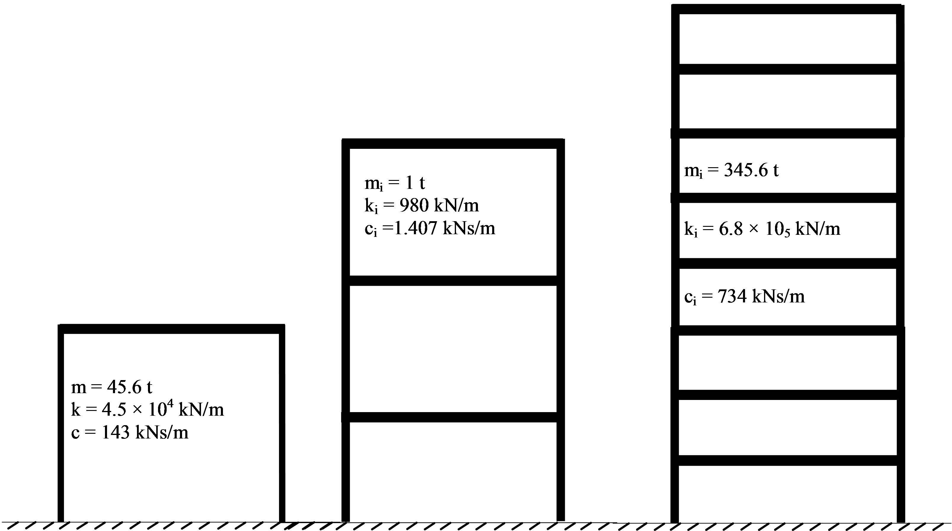
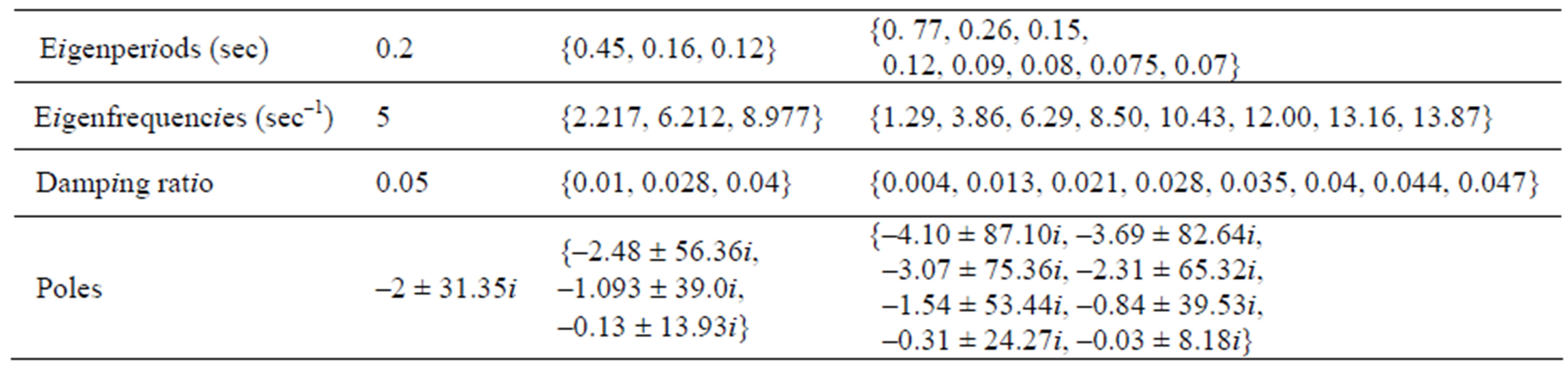
Figure 5. The simulation models and their dynamic characteristics.
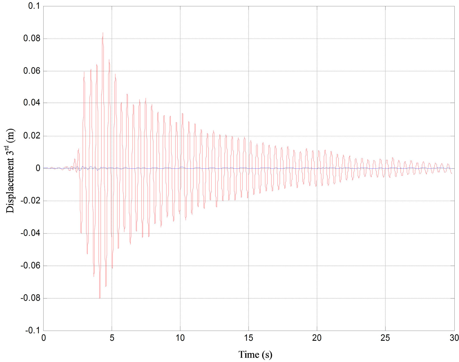
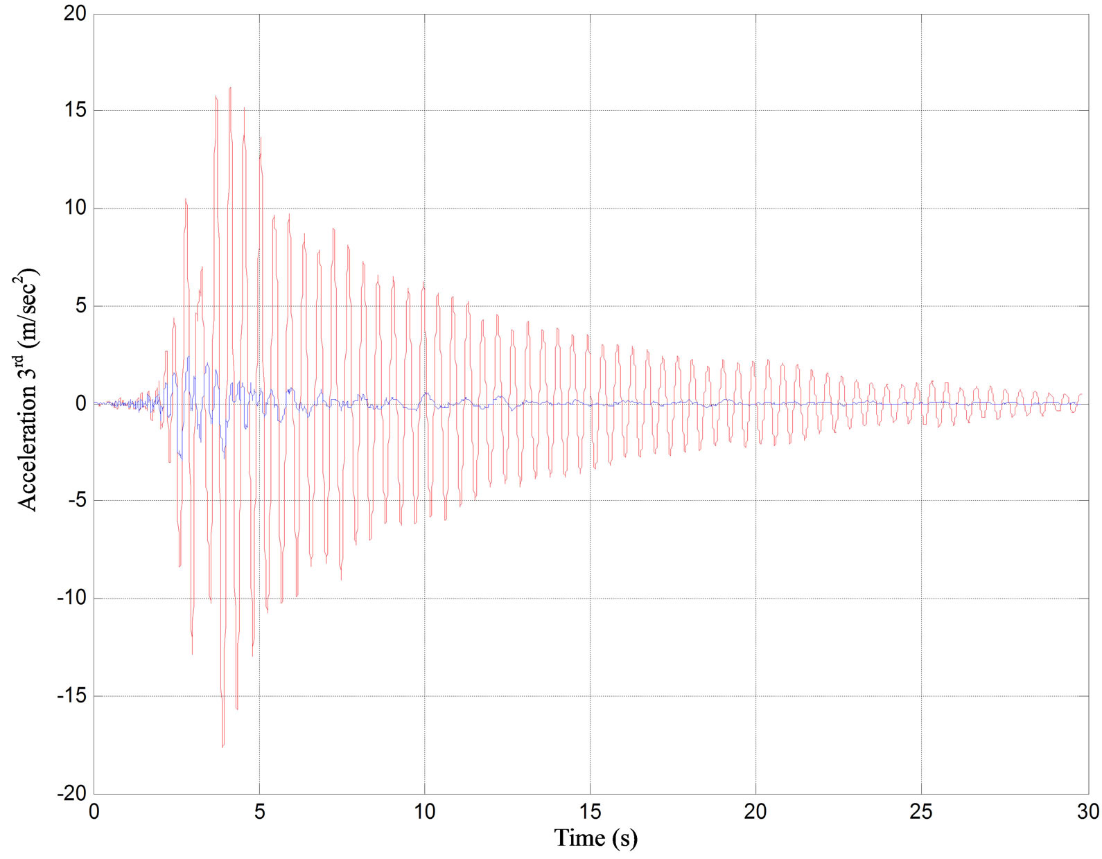
Figure 6. Displacement and acceleration of controlled (bold line) and uncontrolled (thin line) system for 3rd floor of the three-story building subjected to Kalamata (1986) earthquake.
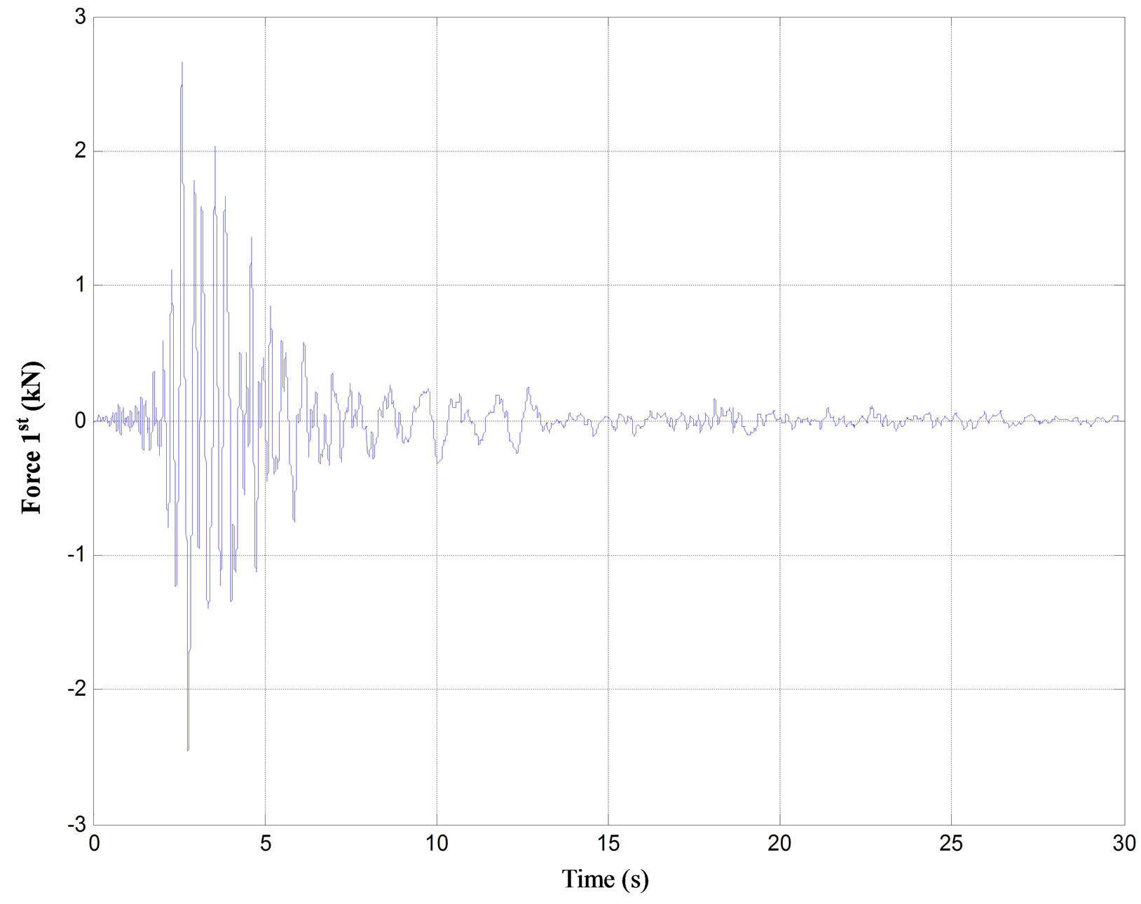
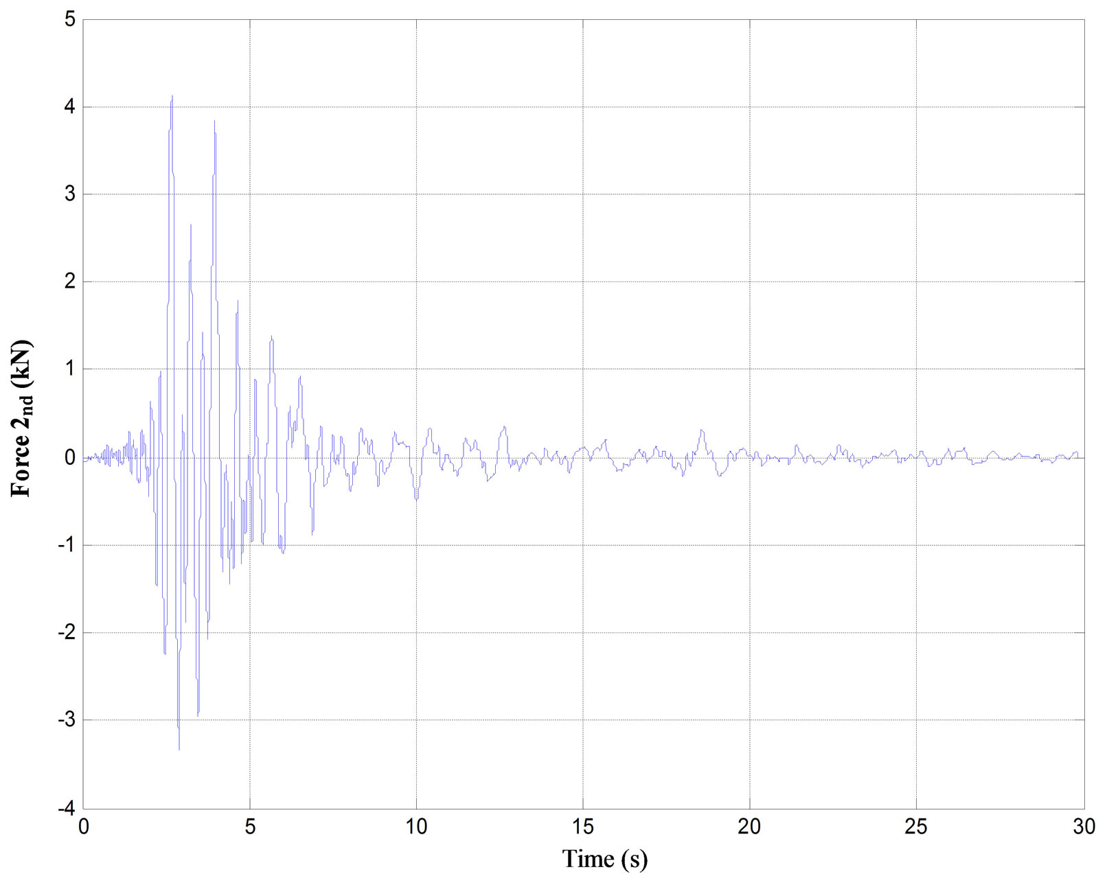
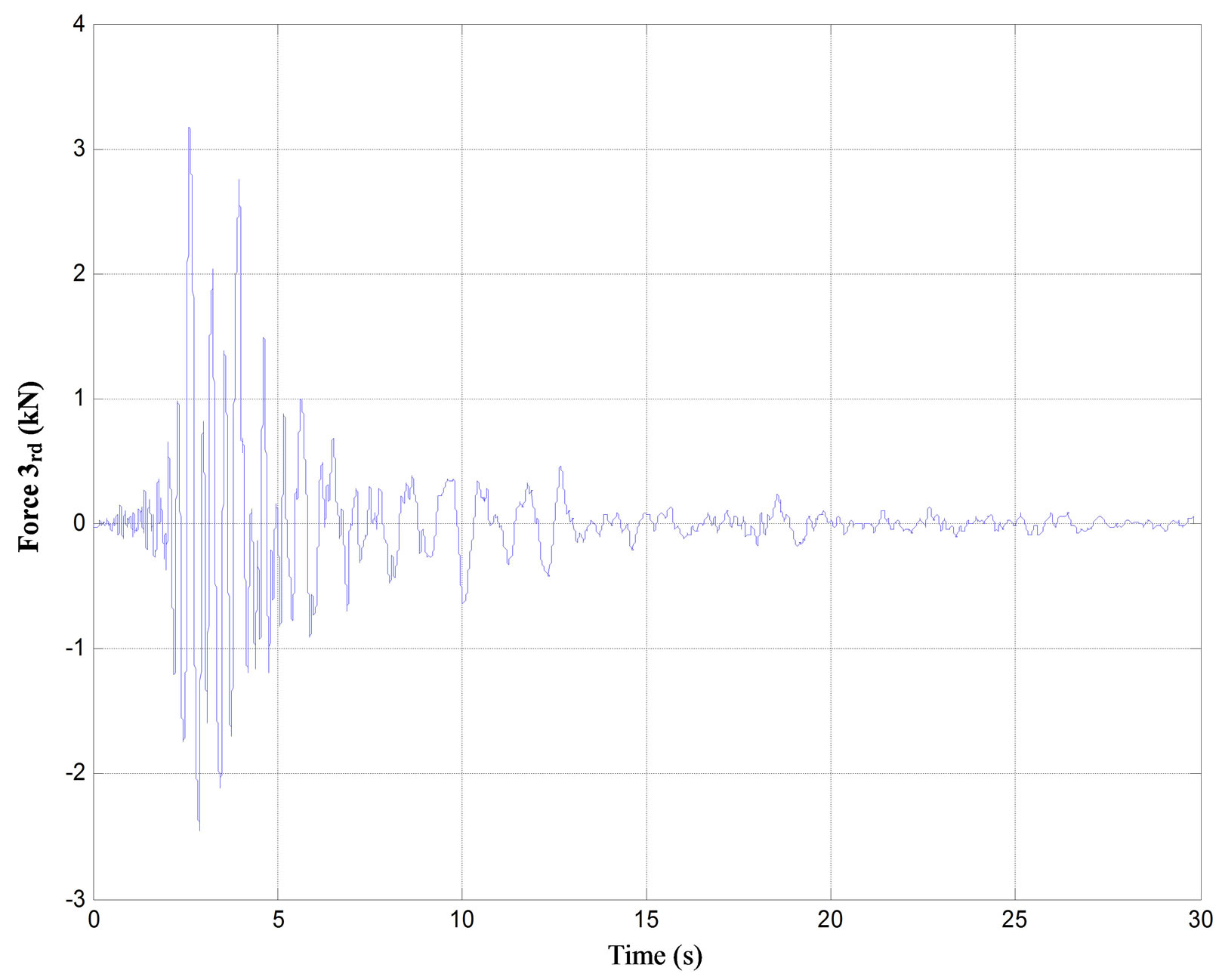
Figure 7. The demanded force for each floor of the three-story building subjected to Kalamata (1986) earthquake.
three systems of Figure 5 subjected to Athens 1999 earthquake excitation are shown in Figures 8 and 9. In these figures the influence on the response of coupling of the two parameters is shown.
The numerical results show that as time delay increases and saturation limit decreases the system becomes unstable. It is also verified that as time delay decreases and the saturation limit capacity increases, the control is more effective and the response is reduced drastically. Furthermore, it is observed that even though for high saturation capacity limit of the device low response is expected, the simultaneous existence of high time delay causes instability.
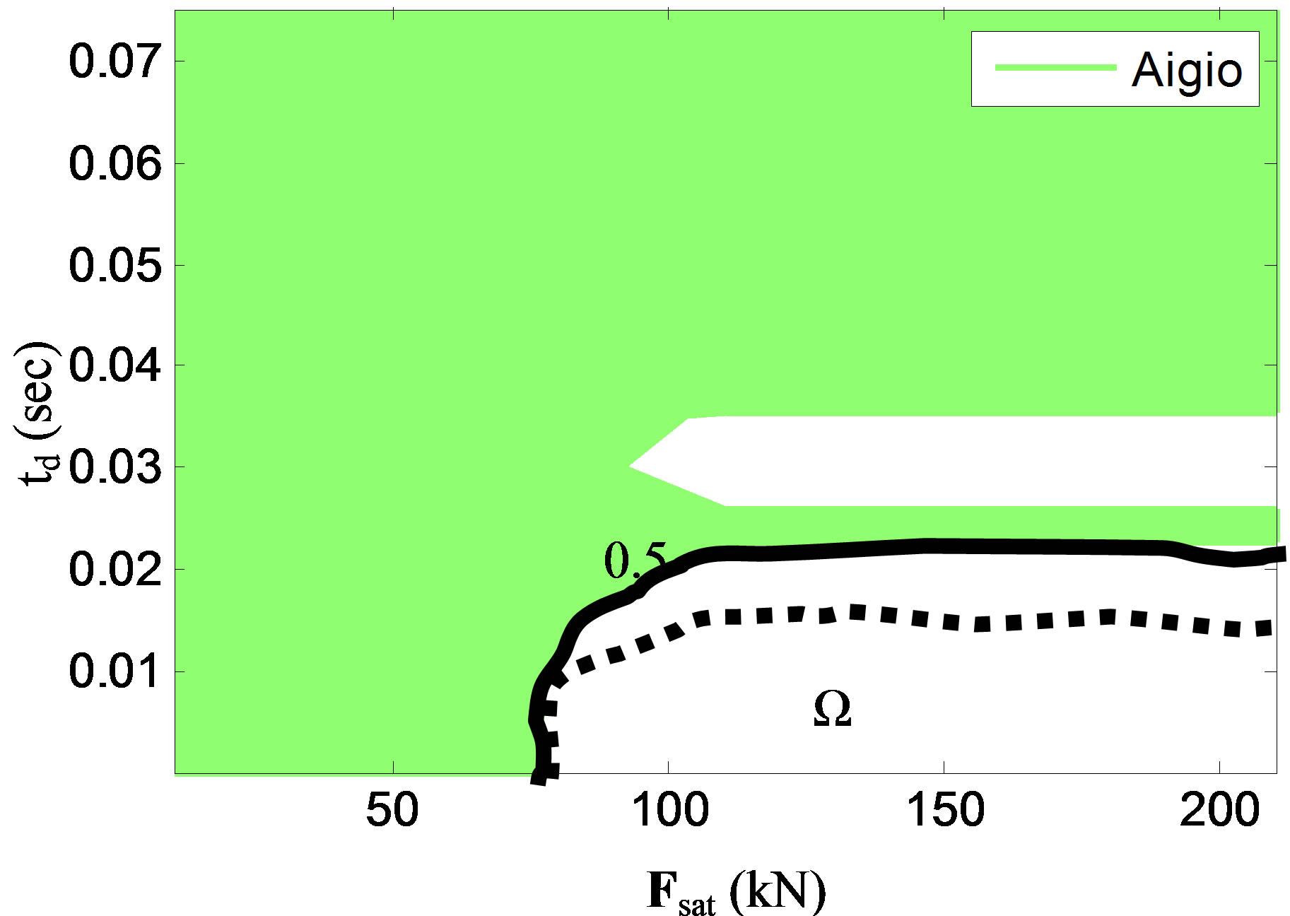
Based on the percentage of response reduction that the designer aims at achieving with the control system, a region Ω, where the response ratio is below the desired percentage, can be determined. The Ω region contains pairs of time delay values and saturation capacity limits for which the response is lower than the predefined response ratio. Values of response ratio and the corresponding limits of the Ω regions are shown in the contour plots of Figure 8 to 10. The border of this region depends on the desired performance level of the controlled structure.
It should be noted that the Ω region depends also on the specific earthquake record considered. In Figure 10 this region is shown for a 0.5 response ratio and for four different earthquakes. With dashed line is the minimum envelope curve of the four above individual curves. The values of time delay and saturation capacity in this region can be considered as design specifications for the control devices and system that is going to be used.
All examples that were analyzed show the negative influence of time delay and saturation capacity. This negative influence is a general trend for structures equipped with control systems. These examples show the need of performing numerical simulations, accounting for the coupling of time delay and saturation capacity, before
 (a)
(a) (b)
(b)
Figure 8. Combined influence of time delay and force saturation on the response of the controlled one-story building, subjected to Athens earthquake excitation. (a) 3D plot; and (b) Contour plot.
 (a)
(a) (b)
(b)
Figure 9. Combined influence of time delay and force saturation on the response of the controlled three-story building (a), and eight-story building (b), subjected to Athens earthquake excitation.
 (a)
(a)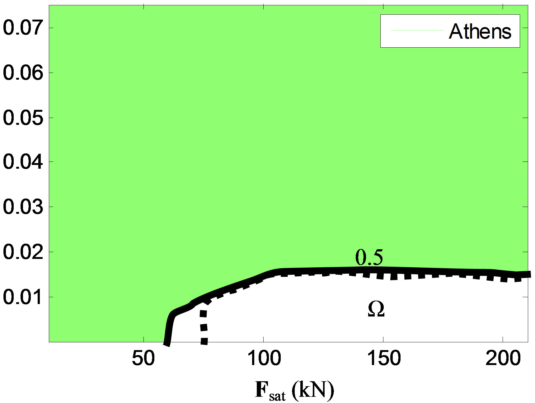 (b)
(b)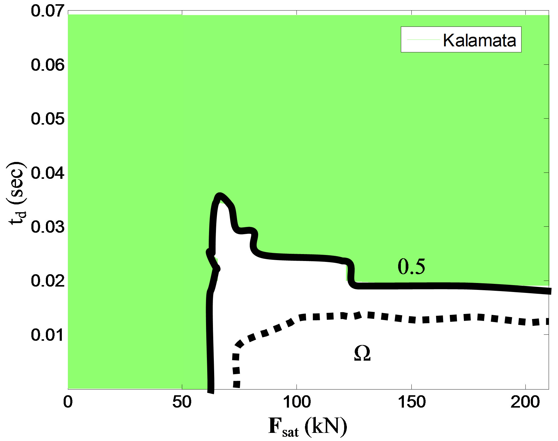 (c)
(c)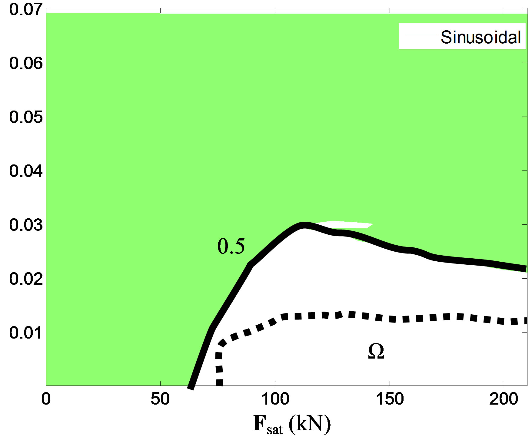 (d)
(d)
Figure 10. The Ω region corresponding to response ratio 0.5 for four different earthquakes and the envelope curve (dashed line).
installing the control system in the building. Such simulations will help to identify the limits of time delay and saturation capacity of the control devices that will keep the building stable and in reduced response compared to the uncontrolled one.
Since all the above results are dependent on the excitation and it is not easy to predict the earthquake ground motion thus conclusions of general validity for upper bound of time delay or lower limits of saturation capacity are not possible, as these phenomena are highly non linear and depend on the earthquake excitation as well as the dynamic characteristics of the specific building. It is therefore suggested that before finalizing the control system, response surfaces like the ones in Figure 10 should be obtained and used as a design tool, assisting the designer to decide about the appropriate values of time delay and saturation capacity that the proposed system should satisfy. In other word, during design, simulations of the structure’s response for a wide range of earthquakes (near fault, far fault) should be performed, and acceptable values of time delay should be obtained for each signal. Then, an envelope of minimum time delay should be obtained and this should be used as a limit for the design of the control system.
4. SUMMARY AND CONCLUSIONS
A control strategy protecting structures from earthquake actions was presented. The strategy is inspired by the reaction of human beings when they are attacked by earthquake action. A pole placement algorithm as a control algorithm was introduced.
The influence of time delay and saturation capacity on the response of controlled building structures subjected to seismic actions was critical to the efficiency of the control strategy. Numerical simulations should be carried out before the installation of any control system, considering the combined effect of these two important parameters. Such numerical simulations will provide limits of time delay and saturation capacity that should not be exceeded, so that the response of the controlled system will be less than that of the uncontrolled one. Based on these limits the engineers will specify values of time delay and saturation capacity of the control devices provided by the manufacture. Numerical simulations show that sufficient reduction of the response, in terms of both displacement and acceleration, can be achieved for all considered earthquakes with reasonable amount of required equivalent control force.
REFERENCES
- Yao, J.T.P. (1972) Concepts of structural control. Journal of Structural Engineering, 98, 1567-1574.
- Yang, J.N., Kim, J.H. and Agrawal A.K. (2000) Resetting semi-active stiffness damper for seismic response control. Journal of Structural Engineering, 126, 1427-143. doi:10.1061/(ASCE)0733-9445(2000)126:12(1427)
- Yang, J. and Agrawal, A. (2002) Semi-active hybrid control systems for non-linear buildings against near-field earthquakes. Engineering Structures, 24, 271-280. doi:10.1016/S0141-0296(01)00094-3
- Yang, J.N. (1975) Application of optimal control theory to civil engineering structures. Journal of Engineering Mechanics Division, 101, 819-838.
- Yang, J.N., Wu, J.C. and Li, Z. (1996) Control of seismic excited buildings using active variable stiffness. Engineering Structures, 18, 589-596. doi:10.1016/0141-0296(95)00175-1
- Yang, J.N., Wu, J.C., Agrawal, A.K. and Hsu, S.Y. (1995) Sliding mode control for non linear and hysteretic structures. Journal of Engineering Mechanics, 121, 1330-1339. doi:10.1061/(ASCE)0733-9399(1995)121:12(1330)
- Yang, J.N., Wu, J.C., Agrawal, A.K. and Hsu, S.Y. (1995) Sliding mode control of seismically excited linear structures. Journal of Engineering Mechanics, 121, 1386-1390. doi:10.1061/(ASCE)0733-9399(1995)121:12(1386)
- Soong, T.T. (1990) Active structural control: Theory and practice. London/New York: Longman Scientific & Technical/Wiley.
- Housner, G.W., Bergman, L.A., Caughey, T.K., Chassiakos, A.G., Claus, R.O., Masri, S.F., Skelton, R.E., Soong, T.T., Spencer, B.F. Jr. and Yao, J.T.P. (1997) Structural control: Past, present and future. Journal of Engineering Mechanics, 123, 897-971. doi:10.1061/(ASCE)0733-9399(1997)123:9(897)
- Spencer, B.F., Dyke, S.J., Sain, M.K. and Carlson, J.D. (1997) Phenomenological model for magnetorheological dampers. Journal of Engineering Mechanics, 123, 230-238. doi:10.1061/(ASCE)0733-9399(1997)123:3(230)
- Spencer, B.F. Jr. and Nagarajaiah, S. (2003) State of the art of structural control. Journal of Structural Engineering, 239, 845-856. doi:10.1061/(ASCE)0733-9445(2003)129:7(845)
- Symans, M.D. and Constantinou, M.C. (1997) Seismic testing of a building structure with semi-active fluid damper control system. Earthquake Engineering and Structural Dynamics, 26, 759-777. doi:10.1002/(SICI)1096-9845(199707)26:7<759::AID-EQE675>3.0.CO;2-E
- Symans, M.D. and Constantinou, M.C. (1999) Semi-active control systems for seismic protection of structures: A state-of-the-art review. Engineering Structures, 21, 469-487. doi:10.1016/S0141-0296(97)00225-3
- Kobori, T. (1990) Experimental study on active variable stiffness system-active seismic response controlled structure. Proceedings of 4th World Congress Council on Tall Buildings and Urban Habitat, Hong Kong, 5-9 November 1990, 561-572.
- Kobori, T. and Kamagata, S. (1992) Dynamic intelligent building—Active seismic response control. Intelligent Structures, 2, 279-274.
- Kurata, N. and Kobori, T. (2003) Reliability of applied semi-active structural control system. Journal of Structural Engineering, 129, 914-921. doi:10.1061/(ASCE)0733-9445(2003)129:7(914)
- Pnevmatikos, N.G. and Gantes, C.J. (2010) Control strategy for mitigating the response of structures subjected to earthquake actions. Engineering Structures, 32, 3616-3628. doi:10.1016/j.engstruct.2010.08.006