Engineering
Vol. 3 No. 3 (2011) , Article ID: 4149 , 4 pages DOI:10.4236/eng.2011.33032
Effect of Increasing Speed on Stress of Biaxial Bogie Frames
1Faculty of Mechanical Engineering, University of Tabriz, Tabriz, Iran
2University of Science and Technology, Tehran, Iran
E-mail: zehsaz@tabrizu.ac.ir
Received December 19, 2010; revised December 27, 2010; accepted January 24, 2011
Keywords: Biaxial Bogie Frame, Speed Increase, Rail Way Roughness, Stress, Finite Element Analysis
ABSTRACT
Increasing the trains’ speed has always been one of the goals of any railway industry and train manufacturers. Also, the influence of the train speed on bogie’s dynamics has an immense importance. Therefore, it is important to analyze the effect of train speed on the stress distribution in different parts of train structure. In this study the result of the increasing speed on the applied stresses of a biaxial bogie frame has been examined. For this purpose, a biaxial bogie frame has been modeled using finite element analysis. Static and dynamic forces applied on the bogie with biaxial frame have been obtained for different speeds and rail roughness. The Von Mises stresses are adopted as equivalent stresses in the strength calculation. The results show that maximum stress always has been induced in the bogie bowl also the increase in bogie’s speed has remarkable effect on the increment of applied stresses in the bogie frame.
1. Introduction
Nowadays, modern technology and its new features bring higher speeds with reliable safety and better ride comfort in rail transportation industries. Lately, railway industry has encountered newer stages of progress such as high speeds, traffic services, load traffics, magnetic trains and etc. In the past, railway progress was influenced by industrial revolution, discovery of steam engines and extensive extractions of coal and iron mines. The first rail way lines started to work in European countries in about 1830s and railway networks reached high congeries in the early 20th century. The rapid advances in train-related industries have introduced high speed trains that resulted in faster transportations. Steam power motors showed wonderful operation during test stages. The maximum speed of these trains was 100 km/h in 1835 in England, 144 km/h in 1890 in France, 213 km/h in 1930 in Germany. Nowadays modern trains can easily travel at the speed of about 250 km/h [1].
Since 1960, developing of finite element method made scientists use this method to improve their calculation in many engineering fields. In this way and by developing these methods, a broad range of related software’s having been introduced and developed [2]. The use of finite element method for designing, simulating and optimizing the performance of the rail way vehicles grows day by day. This method is often used to analyze the stress of the body of wagon, bogie, wheel, and rail [2]. Zerbst et al. have provided an excellent review on the application of finite element methods on fracture mechanics in railway applications [3]. Kim [4] has carried out fatigue assessment of a tilting bogie frame for Korean train industry using finite element analysis and static tests. Telliskivi et al. [5] designed finite element-based software to investigate interactions between rails and wheels. Improving and optimizing the rail way vehicles and bogie wagons, has been done by dynamic analysis using finite element methods, as well. For example, Ramji et al. [6] used this method to investigate dynamic behavior of railway, coach and bogie. Yoshimura et al. [7] used numerical simulation methods to study the dynamic reaction of vehicle-track. Messouci [8] has carried out a comparative study on the lateral stability of the rail vehicles. Shock caused by collision of trains has been analyzed by Finite Element Method (FEM) as well [9].
Generally, the simulation of rail based-vehicles is calculated in two distinct ways, called longitudinal dynamic and lateral dynamic. In longitudinal dynamics, some collection of wagons that are connected to each other by a hook, are the scope of analysis. For example, the strikes imported from collision of wagons, were analyzed by Yi M.Y. [10]. Fukasawa [11] has calculated striking forces applied to the hooks of bi-axis wagons in braking session. Also Oyan [12] studied subways’ longitudinal dynamics. For the simulation of the lateral dynamics of train, polar effects of wheel and rail and derailing of trains are mostly used. For example in 1996, a model that considered elasticity and damping coefficient of rails, and railways cushioning was studied by Zhia and his colleagues [13] for studying on derailing of trains that was appeared due to their misalignment and rails twist. Also, the wheel flange climb derailment and wheel impact derailment are studied by Zeng and Wu [14]. There are also models which study both the lateral and longitudinal dynamics simultaneously. For example in 1990 the tensional and compressive forces applied to hook in the movement of wagon in its turns with high velocity has been measured by AAR, utilizing a special rail vehicle [15]. In 1994 Dong and his colleagues [16] used a simple dynamical model of train that included only one axis to analyze the limited components of tracks.
One of the wagon’s components is bogie that is called upon wagon’s movement system and it consists of the frame (longitudinal and lateral beam), spring system (suspension), wheel and axis system and brakes and related instrument system. In addition to the homogenous distribution of frame’s weight, bogie makes the wagon to perform smoothly on turns. It also provides track’s safety, the convenience of frame movement on railways with different lateral lines and it increases the wagon’s loading capacity. Therefore, one can conclude that bogie is one of the most important components in wagon frame. There are several standards for strength evaluation of the conventional bogie frame such as JIS E 4207 [17] and UIC 615-4 [18]. However, no standard has been established regarding the bogie frame of the tilting trains yet.
2. Methods
All previous studies mentioned above do not quantify the change in stress distribution in bogie frame caused by the increase in train velocity Therefore, in this research, bi-axis bogie frame (I79) has been modeled to investigated the effect of train’s velocity on the induced stresses in the bogie. For this purpose the velocity of the train has been changed from 20 m/s to 40 m/s at different loads. The analysis method is shown in Figure 1.
A solution method has also been used to analyze the dynamic behaviour of the system. It has been assumed that the train is passing through the ruggedness of the rail-way with a big pockets shape wave. Bogie suspension system is simulated with three degrees of freedom

Figure 1. Flowchart of analysis method.
and the forces and reactions of the initial and secondary suspension systems have been calculated. The out put of this stage has been used in the finite element (FE) based stress analysis. For this purpose, firstly, a FE model has been developed and is verified using modal analysis. Then, the stress analysis of the bogie frame has been carried out and the effect of train speed on this stresses has been investigated.
3. Bogie Frame
The bogie as shown in Figure 2 is the moving part of any wagon that on account of its effect on the tracks, the movement and advancement in the direction of the rail will be possible.
Bogie is formed of several parts: two wheel and axis (1), two side beams (2), cradle (3), cushions (8), suspension system (4) and levering of brake (5).
4. Dynamical Simulation of the Suspension System
Primary suspension system is positioned between the wheel and the side beam that is formed of two cap springs on the arm of each roller bearing. There are eight cap-springs for each primary suspension system. This system should absorb shocks and sudden vibrations. So it has a considerable elasticity and damping coefficient. In this model, each cap-spring has been simulated using a couple of parallel spring-dampers in which they have an equal spring and damping coefficients due to the same kind of the plastic that is used. The whole bogie has also been modeled using a spring and damper with coefficients that are eight times bigger than the coefficients of
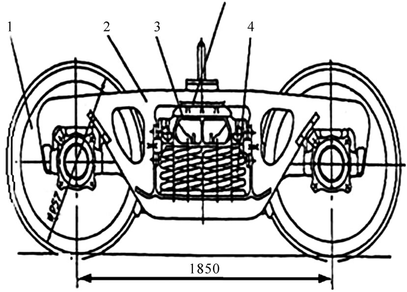
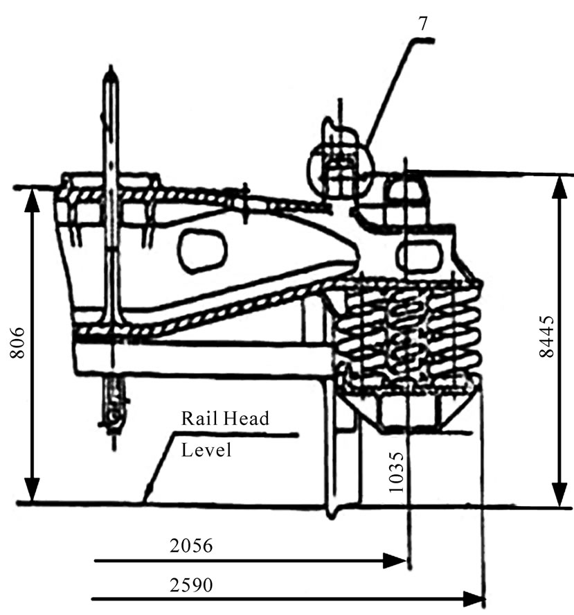
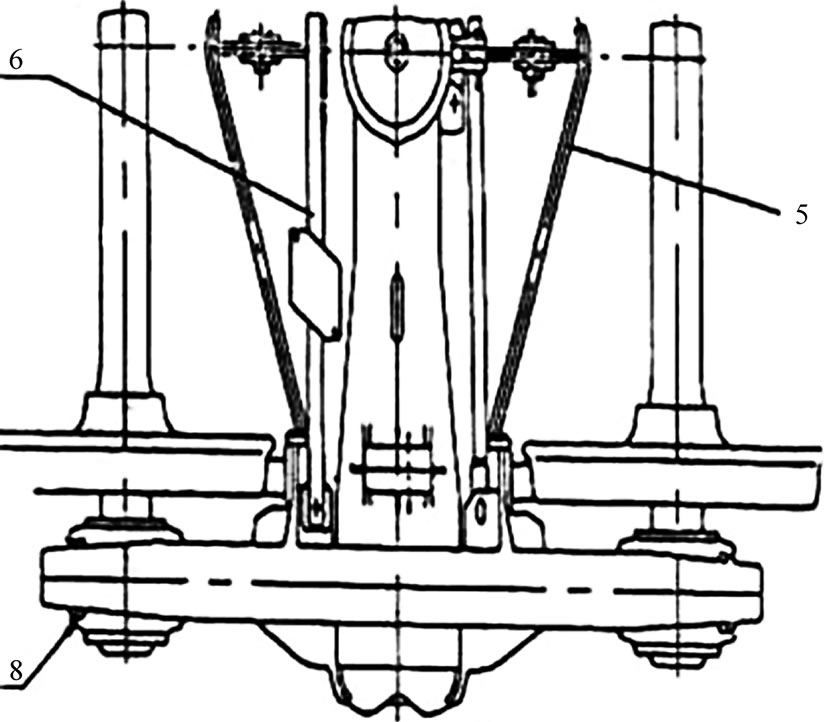
Figure 2. Biaxial bogie I79 [19].
the cap-springs.
Second suspension system consists of fourteen sets of internal and external helical springs and four friction dampers that ten sets of these springs are used straightly between side beam and the cradle and four sets are between side beam and friction damper. Springs are modeled in an equal manner in the dynamic model. Introduction of the friction dampers make the treatment of the model non-linear. The performance of these dampers can be influenced by the environmental conditions (like humidity, etc.). Also, their damping effect depends on the magnitude and rate of the applied load.
In this study, viscose dampers have been used instead of friction dampers. In order to obtain equal viscose dampers, the dissipated energy of each cycle should be computed, however for this bogie-design, it is theoretically impossible because of the variation of the normal forces. But if we experimentally find the diagram of the force-displacement for a damper, the area of this diagram will give the wasted energy and using this quantity, the damping coefficient can be found.
The dynamic model has also two masses, one of them is total mass of side beams and is between two suspension systems and the other includes mass of wagon, load and horizontal beam (the Cradle) that is on the second hang. The bogie and the suspension system are shown in Figure 3 and the dynamic model which is used to study its behaviour is presented in Figure 4. Assumptions which are considered for bogie’s simulation are:
• Rail’s profile is symmetric in both sides.
• Springs and Dampers are completely ideal.
• Sliding and tolerances haven’t been considered.
• The effect of longitudinal vibrations has been ignored, because it is insignificant in comparison with the effect of body’s vertical movements.
• For reducing the degrees of freedom and having a simple model, system is considered as a single input model.
5. Equations of Dynamic Model
Once an appropriate physical model has been developed,
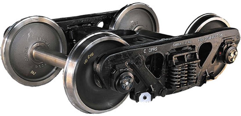
Figure 3. Bogie suspension system [19].
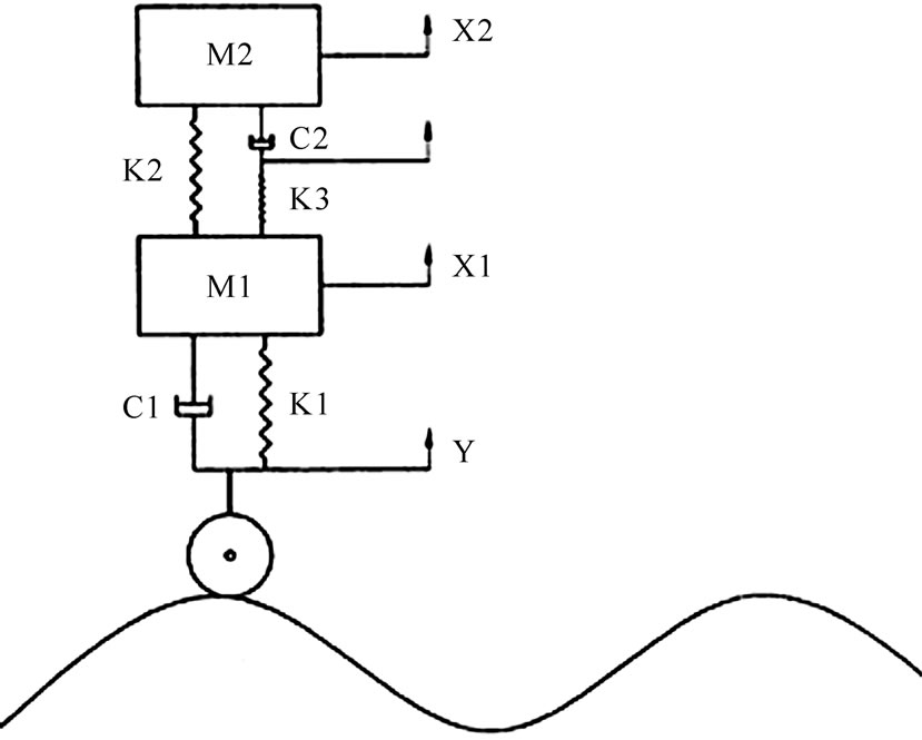
Figure 4. Dynamic model of the bogie.
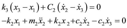
dynamic equations used in the model can be obtained. Differential equations of the bogie’s model in vertical directions are proposed as:
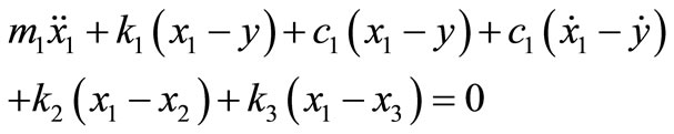 (1)
(1)
After simplification:
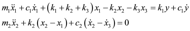 (2)
(2)
After simplifying:
 (3)
(3)
After simplifying:
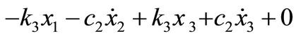 (4)
(4)
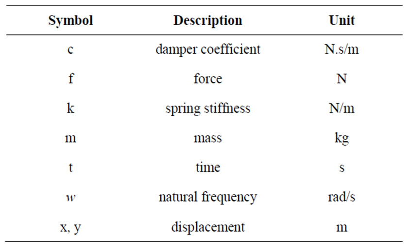
The parameters that are used in the above equations are:
• m1: Total mass of side beams.
• m2: Total mass of the wagon, the load and the cradle.
• x1: Displacement of m1.
• x2: Displacement of m2.
• x3: Displacement of the connection point of damper and spring at secondary suspension.
• k1: The equal elasticity coefficient at first suspension.
• k2: The equal elasticity coefficient of springs that that are lied directly between of linear beam and cradle.
• k3: The equal elasticity coefficient of springs which stand between the longitudinal beam and frictional damping.
• c1: The equal damping coefficient at first suspension.
• c2: The equal damping coefficient of viscous for frictional dampers.
And finally, matrixes of mass, stiffness, damping and forces for the model, may be obtained as below:
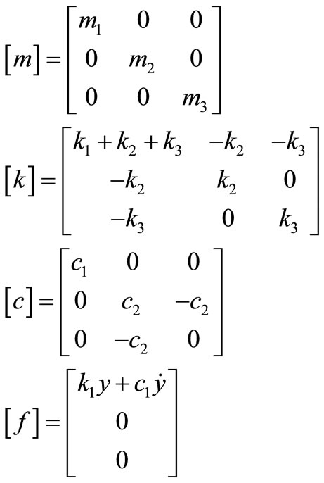 (5)
(5)
The matrixes above define a system of equations as:
 (6)
(6)
A sinusoidal wave for unevenness of the railroad has been considered in this study which provides an exciting force that is used to carry out the harmonic analysis of the system of Equation (6). So, the particular answer for Equation (6) can be considered as:
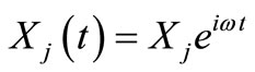 (7)
(7)
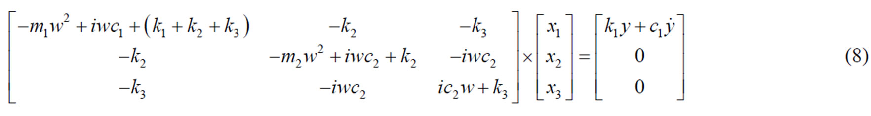
Generally, “Xj” is a complex number that depends on  (natural frequency) and parameters of the system. By superseding the particular answer in Equation (6), we will have (8).
Now, the main task is the solution of Equation (8) which can be solved using an appropriate computer program. The applied forces to the parts of the bogie frame can be calculated by obtaining x1, x2 and x3 as follows:
•  : Applied force from the equal spring of each cap spring to the side beam
•  : Applied force from the equal damper of each cap spring to the side beam
•  : Applied force from secondary suspension system to the side beam
•  : Applied force from secondary suspension helical springs to the cradle The parameters used above are:
•  : The equal elasticity coefficient of each capspring
•  : The equal elasticity coefficient of each set from secondary helical suspension springs (the sum of the elasticity coefficient of an internal spring and an external spring)
•  : The equal damping coefficient of each cap spring
•  : The equal viscous damping coefficient of each frictional damper in the secondary suspension
6. Solving Dynamic Model and Results
To carry out the necessary dynamic analysis, it is necessary to have a model of the vehicle for calculating the values of the induced forces and displacements which are applied to the vehicle tires and carried through the suspension system in to the upper hand systems like chassis and its attaching links. The input of this analysis, is the displacement due to the road surface roughness and the response of the suspension system as spring and damper reaction forces will be produced because of their stiffness and resilience. These forces will be transferred to the upper hand systems. Because of the alternative and repetitive nature of these forces, they may cause fatigue in the vehicle parts and in their joints.
To develop a dynamic model and to find the reaction forces, different models such as 1/4, 1/2 or even a full model of the vehicle can be used and the latter one is the most sophisticated model and takes into account the effect of pitch, roll and bounces caused by passing the vehicle over a road with random roughness profile.
To carry out the dynamic analysis using numerical simulations, because of the large volume of data required for the real and accurate body models, usually simplified models can been used. However, to obtain accurate solutions, the major parameters, such as mass properties and inertia should be defined in the model in a correct way. Also, due to the large number of mechanical parts in the real vehicle body, their equivalent mass and inertia has been obtained using Solid Works software and has been introduced in the simple model shown in Figure 4. By introducing the effect of the parts, an accurate but a simple model has been developed to study the dynamic behavior of the vehicle. In addition, the role of other parts, such as tires, suspension system itself and axels have also been taken into account. The damping effect of the suspension system has been introduced to the model. The effect of the flexibility of the joining parts has also been taken into account to improve the accuracy of the model.
Table 1 presents the major parameters which define the railway profile.
Table 2 gives the characteristics of the suspension system and Table 3 provides the equal values which have been used to model the bogie. After describing the equations of the model in a parametric way, these system of differential equations have been solved using numerical methods and the calculated amounts for the forces applied by each component are given in Tables 4 and 5.
7. FE Based Analysis of the Bogie Frame
The FE analysis of the bogie model has been carried out using the computer code ANSYS [20]. Since the bogie frame is a shell, Shell elements have been used to produce the FE model. In this method, we draw the forming surfaces of bogie frame and then as interweaving, the thickness of each part is given as a constant of the element. The material properties which have been used to provide the FE model are given in Table 6.
The first step in interweaving surfaces is the determination of the elements’ type. In this model Shell 93 element has been used which is one of the shell elements defined in ANSYS [20]. Shell 93 is particularly well suited to model curved shells. The element has six degrees of freedom at each node: translations in the nodal x, y, and z directions and rotations about the nodal x, y, and
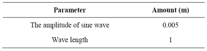
Table 1. Uneven road specification.
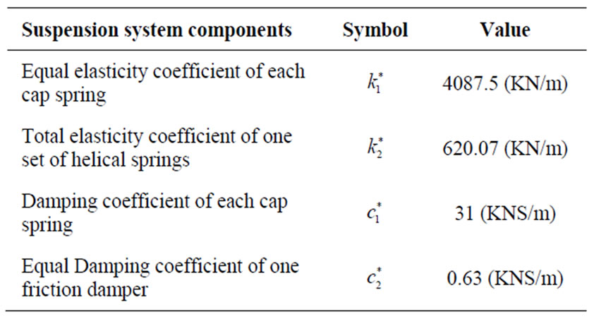
Table 2. Equal parameter of each part of suspension system [19].
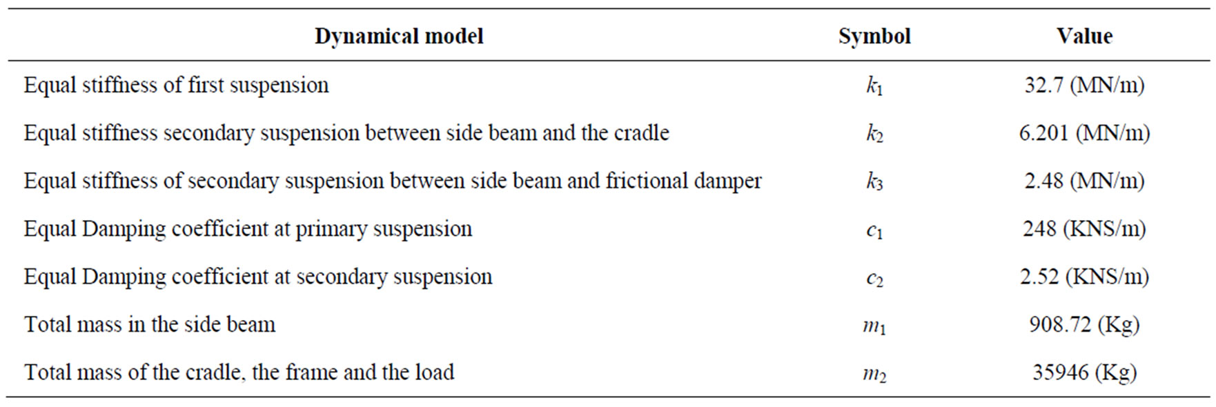
Table 3. Parameter of simulated dynamic model [19].
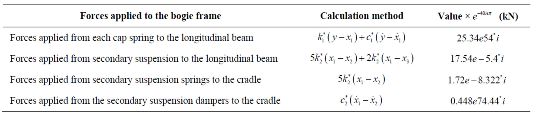
Table 4. The forces applied to the bogie frame in velocity of 20 m/s.

Table 5. Forces applied to the bogie frame at velocity of 40 m/s.
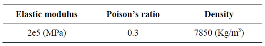
Table 6. Properties of materials.
z-axes. The deformation shapes are quadratic in both in-plane directions. The element has plasticity, stress stiffening, large deflection, and large strain capabilities. The element is defined via 8 points, 4 diameters and properties of material in main axis’ direction.
To develop a FE model of the bogie, it is needed to link side beam and cradle via second suspension (overlap or overlay) at the same file and define spring and damper elements as secondary suspension between side beam and the cradle. It is worth to remind that in order to define secondary suspension system, 16 combin40 elements have been utilized in which the intern elasticity and damper coefficient are defined as element constants [20]. COMBIN40 is a type of element defined in ANSYS to carry out modal analysis and is a combination of a spring-slider and damper in parallel, coupled to a gap in series. A mass can be associated with one or both nodal points. The element has one degree of freedom at each node, either a nodal translation or rotation.
To carry out the modal analysis, also mass21 elements have been used to model frame mass and bogie. These masses are specified using 8 elements. MASS21 is a point element having up to six degrees of freedom: translations in the nodal x, y, and z directions and rotations about the nodal x, y, and z axes. Supports are defined in modal analysis and applied forces are in Tables 4 and 5 which have been obtained through solving system of Equations (1)-(8).
8. Results of FE Analysis
The natural frequencies are given in Table 7. These data have been used to make sure that the frequency of the exciting forces is not close to the natural frequencies of the system and resonance will not occur.
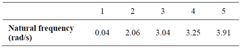
Table 7. Natural frequencies from modal analysis.
To observe the effect of train velocity on the stress distribution, the harmonic analysis has been carried out using the applied forces given in Tables 4 and 5 with the frequencies given in Table 8. The effective or Von Mises stress distribution in bogie frame with train velocity of 20 m/s is shown in Figure 5. Also the maximum values for the effective stress at two different train speeds of 20 and 40 m/s are given in Table 9.
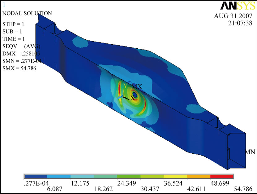
To observe the effect of train velocity on the stress distribution, without considering the effect of the frequency of the applied forces, maximum value (amplitude) of the forces which have been obtained using dynamic analysis (see Tables 4 and 5) have been applied to the FE model and static analysis have been carried out to obtain stress distribution in cradle and side beams separately and the results are shown in Figure 6. The values of the maximum stresses are given in Table 10.
9. Discussion and Conclusions
In this study, a two sided bogie frame has been modeled in order to determine the effect of train’s speed on the induced stresses. For this purpose, it has been assumed that the train is passing through the ruggedness of the rail with a big pockets shape wave. Bogie Suspension system is simulated with three degrees of freedom and a numerical solution method has been used to analyze the dynamic behaviour of the system. The forces and reactions of the initial and secondary suspension systems have been calculated. Then a FE model has been developed to analyze the stress distribution in the bogie frame with the use of forces applied to the frame bogie model which have been obtained using dynamic solution. Also, by using bogie frame’s modal analysis, first five natural frequencies of the system have been calculated. To calculate the stresses of the system both harmonic and static analysis have been carried out using FE based computer code ANSYS. The results of the harmonic and static analysis on bogie frames show that maximum stress occurs in the bogie bowl. Comparing the results which have been obtained using two train speeds of 20 (m/s) and 40 (m/s), show that by increasing the speed, the amount of maximum stress induced in the bogie increases significantly: at the speed of 40 (m/s) the maximum stress is about 26% more than the value of the maximum stress at the velocity of 20 (m/s). This shows that by increasing the velocity, the amount of stress in different
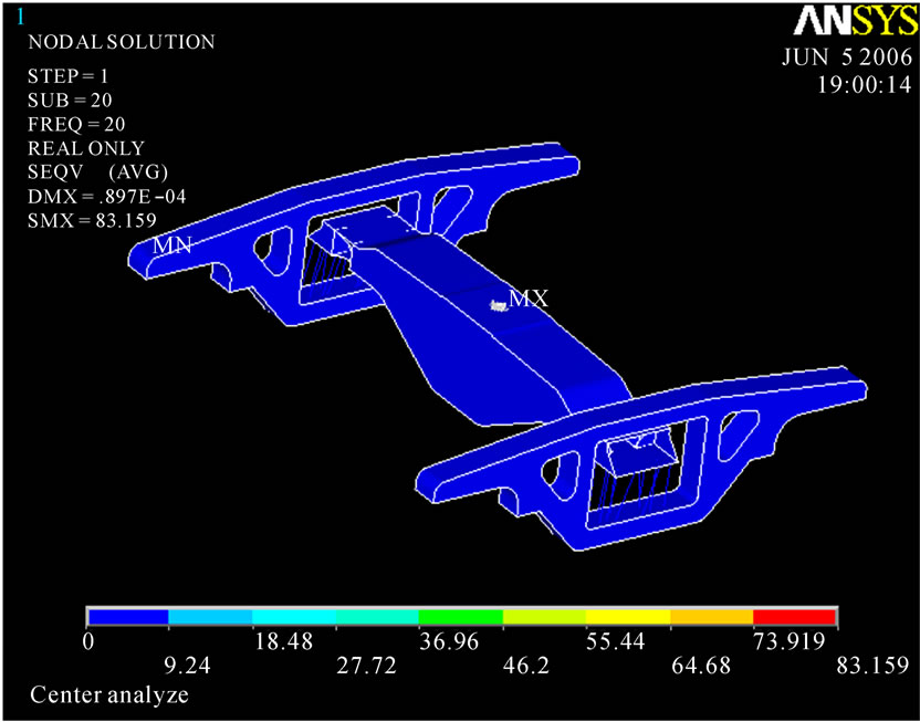
Figure 5. Von Mises stress of Bogie frame at 20 m/s (harmonic analysis).
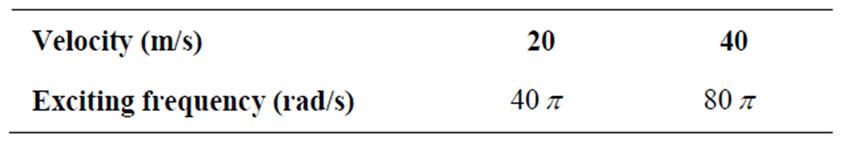
Table 8. Frequency of applied force.
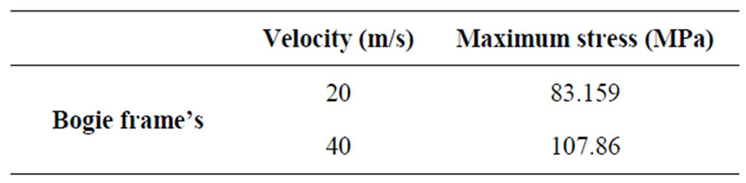
Table 9. Maximum stresses from harmonic analysis.
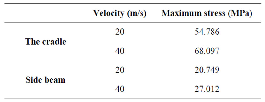
Table 10. Maximum stresses from static analysis.
parts of bogie increases. Knowing that the amplitude of the stress alteration has a significant effect in fatigue life of engineering parts, we can expect that at higher velocities the fatigue life of the parts will decrease considerably. Also the change of velocity may have the same effect, so by reducing the stop and go numbers for a train the life of engineering parts will increase from this point of view.
In this study a simple dynamic model has been used and therefore, only the effect of vertical displacement on the stresses induces in the bogie has been considered. Although this is a major effect and most of the stresses are due to the vertical displacement, but other factors such as longitudinal and lateral vibrations should also be
 (a)
(a)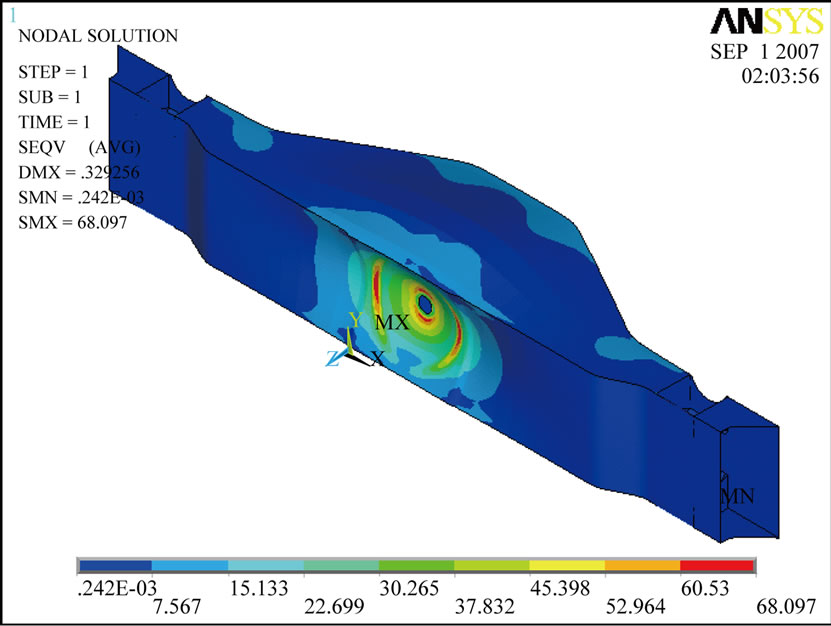 (b)
(b)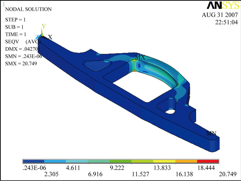 (c)
(c)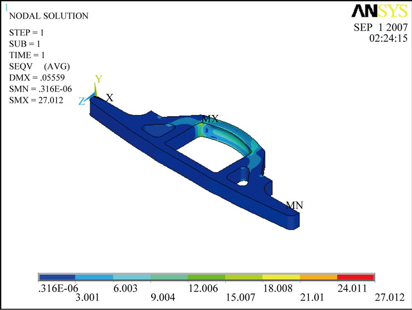 (d)
(d)
Figure 6. Von Mises stress of cradle and side shaft obtained using static analysis at two different speeds of train. (a) Stress of cradle at 20 m/s; (b) Stress of cradle at 40 m/s; (c) Stress of side shaft at 20 m/s; (d) Stress of side shaft at 40 m/s.
considered. Therefore, for future work, a complete 3D model may be used to carry out dynamic solution and also the effect of acceleration or deceleration of the train can be taken into account.
10. REFERENCES
- J. Gutiérrez, R. González and G. G. Gómez, “The European High-Speed Train Network: Predicted Effects on Accessibility Patterns,” Journal of Transport Geography, Vol. 4, No. 4, December 1996, pp. 227-238. doi:10.1016/S0966-6923(96)00033-6
- F. Xia, C. Cole and P. Wolfs, “The Dynamic Wheel-Rail Contact Stresses for Wagon on Various Tracks,” Wear, Vol. 265, No. 9-10, October 2008, pp. 1549-1555. doi:10.1016/j.wear.2008.01.035
- U. Zerbst, K. Madler and H. Hintze, “Fracture Mechanics in Railway Applications –– An Overview,” Engineering Fracture Mechanics, Vol. 72, No. 2, January 2005, pp. 163-194. doi:10.1016/j.engfracmech.2003.11.010
- J. S. Kim, “Fatigue Assessment of Tilting Bogie Frame for Korean Tilting Train: Analysis and Static Tests,” Engineering Failure Analysis, Vol. 13, No. 8, December 2006, pp. 1326-1337. doi:10.1016/j.engfailanal.2005.10.007
- T. Telliskivi, U. Olofsson and P. Kruse, “A Tool and a Method for FE Analysis of Wheel and Rail Interaction,” Royal Institute of Technology, Stockholm, 2000.
- K. Ramji, V. K. Goel, S. A. S. O. Rao and M. K. Naidu, “Dynamic Behaviour of Railway Coach and Bogie Frame using Finite Element Analysis,” Journal of Institution of Engineers (India), Vol. 87, January 2007, pp. 7-17.
- A. Yoshimura, M. Miwa and Y. Kawasaki, “Study on Numerical Simulation Methods of the Railway VehicleTrack Dynamic Interaction,” Proceedings in Applied Mathematics and Mechanics, Vol. 8, No. 1, 2008, pp. 10833- 10834.
- M. Messouci, “Lateral Stability of Rail Vehicles –– A Comparative Study,” ARPN Journal of Engineering and Applied Sciences, Vol. 4, No. 3, May 2009, pp. 13-27.
- A. Tănăsoiu and I. Copaci, “Study on the Shock Caused by Collision of Railway Vehicles,” International Journal of Mechanics, Vol. 2, No. 3, pp. 67-76.
- M. Y. Yu, X. Sun and J. B. Lin, “Analyses to Mechanism of Train longitudinal Impulse,” Proceedings of 4th International Heavy Haul Railway Conference, Brisbane, 9-10 September 1989, pp. 591-594.
- K. Fukasawa, “Coupler Forces of 1000t Class Two-Axle Freight Train,” Quarterly Report of RTRI, Vol. 33, No. 3, August 1992, pp. 166-168.
- C. Oyan, “Dynamic Simulation of Taipei EMU Train,” Vehicle System Dynamics, Vol. 30, No. 2, 1998, pp. 143- 167. doi:10.1080/00423119808969441
- W. M. Zhai, C. B. Cai and S. Z. Guo, “Coupling Model of Vertical and Lateral Vehicle/Track Interaction,” Vehicle System Dynamics, Vol. 26, No.1, 1996, pp. 61-79. doi:10.1080/00423119608969302
- J. Zeng and P. Wu, “Study on the Wheel/Rail Interaction and Derailment Safety,” Wear, Vol. 265, No. 9-10, October 2008, pp. 1452-1459.
- Association of American Railroad, Mechanical Division, “Manual of Standards and Recommended Practices,” Vol. C-II, Section 2.16, 1990.
- R. G. Dong, S, Sankar and R. V. Dukipati, “A Finite Element Model of Railway Track and Its Applications to the Wheel Flat Problem,” Proceedings of the Institution of Mechanical Engineers, Vol. 208, 1994, pp. 61-72. doi:10.1243/PIME_PROC_1994_208_234_02
- JIS E 4207-2004, Truck Frames for Railway Rolling Stock––General Rules for Design, June 2004.
- UIC Code 615-4, Motive Power Units––Bogies and Running Gear-Bogie Frame Structure Strength Tests, International Union of Railways, Paris, 1994.
- Research and Development Unit of Wagonpars Company, 2003. http://www.wagonpars.com/en/H665.html
- ANSYS User’s Manual for Revision 5.1, Swanson Analysis Systems, Inc., Houston, 1995.