Wireless Engineering and Technology
Vol.3 No.3(2012), Article ID:21473,6 pages DOI:10.4236/wet.2012.33025
Plus Shape Slotted Fractal Antenna for Wireless Applications
![]()
1S.D.M. Institute of Technology, Ujire Mangalore, India; 2University Science Instrumentation Center, Gulbarga University, Gulbarga, India; 3Department of PG Studies and Research in Applied Electronics, Gulbarga University, Gulbarga, India.
Email: Jagadeesh.sd69@gmail.com, vanirm12@rediffmail.com, prbhakar_hunagund@yahoomail.com
Received April 28th, 2012; revised May 26th, 2012; accepted June 3rd, 2012
Keywords: Fractal Antenna; Multi Frequency; Size Reduction; Wireless Application; Plus Shape Antenna; Slotted Antenna
ABSTRACT
Fractal antennas are characterized by space filling and self-similarity properties which results in considerable size reduction and multiband operation as compared to conventional microstrip antenna. This paper outlines a multiband antenna design based on fractal concepts. Fractal antennas show multiband behavior due to self-similarity in their structure. The plus shaped fractal antenna has been designed on a substrate of dielectric constant EURr = 4.4 and thickness 1.6 mm. The proposed antenna is characterized by a compact size and it is microstrip feed fractal patch of order 1/3. It is observed that the antenna is radiating at multiple resonant frequencies. The resonant frequency is reduced from 2.2 GHz to 900 MHz after I & II iterations respectively. Thus considerable size reduction of 81.77% & overall bandwidth of 12.92% are achieved. The proposed antenna is simulated using the method of moment based commercial software (IE3D) and it is found that simulated results are in good agreement with the experimental results.
1. Introduction
In the study of antennas, fractal antenna theory is a relatively new area. The emergence of antennas with fractal geometries has given an answer to two of the main limitations started by Werner (1999) of the classical antennas, which are single band performance and dependence between size and operating frequency. The term “fractal” means broken or irregular fragments. It was originally coined by Mandelbrot (1983) to describe a family of complex shapes that possess an inherent self-similarity or self-affinity in their geometrical structure. Jaggered (1990) defined fractal electrodynamics as an area in which fractal geometry was combined with electromagnetic theory for the purpose of investigating a new class of radiation, propagation and scattering problems. One of the most promising area fractal electrodynamics researches is in its application to antenna theory and design. There are varieties of approaches that have been developed over the years, which can be utilized to archive one or more of these design objectives. The development of fractal geometry came largely from an in depth study of the pattern nature, with the advance of wireless communication system and their increasing importance wide band and low profile antennas are in great demand for both commercial and military applications [1]. A fractal is a rough or fragmented geometric shape that can be split into parts, each of which is a reduced-size copy of the whole and this property is called self-similarity. Fractal [2] geometries are composite designs that repeat themselves or their statistical characteristics and are thus “self-similar” fractal geometry finds a variety of applications in engineering. Fractal geometry is space filling contours of regular or irregular shapes [3-6], and is super imposed of too much iteration and they describe the self-similar property of fractal geometry [7]. Fractals are a class of shapes which have not characteristic size. Each fractal is composed of multiple iterations of a single elementary shape the iteration can continue infinitely, thus forming a shape within a finite boundary but of infinite length or area. Fractal has the following features 1) It has a finite structure at arbitrarily small scales; 2) It is too irregular to be easily described in traditional Euclidean geometric; 3) It is self-similar; 4) Simple and recursive [8]. Modern telecommunication systems require the antenna with wider bandwidth and smaller dimension than conventionally possible. This has initiated antenna research in various directions, are of which is by using fractal shaped antenna elements. In recent years several fractal geometries have been introduced for antenna application with varying degree of success in improving antenna characteristics. Some of these geometries have been particularly useful in reducing the size of the antenna, while other designs aim at incorporating multiband characteristics. These are low profile antennas with moderate gain and can be made operative at multiple frequency bands and hence are multifunctional [9]. In our present work we focus on generation of multifrequency which yields increases the bandwidth and size reduction of antenna. A plus shape patch is taken as a base shape and in first iteration four other plus shape patches of the order of 1/3 of base shape are placed touching the base shape. Similarly second iterations are taken by further placing plus shaped patches at even reduced scales. It is found that as the iteration number and iteration factor increases, the resonance frequencies become lower than those of the zero iteration, which represents a conventional plus shape patch.
2. Design Consideration
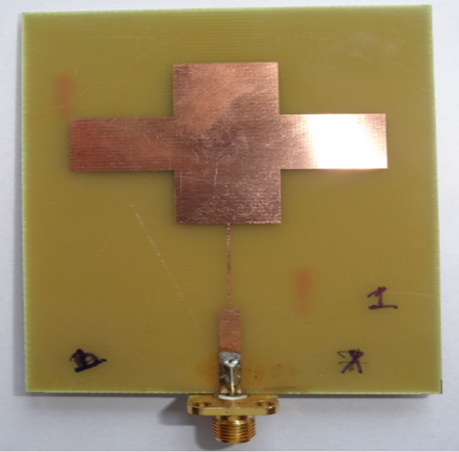
The base shape of the plus shaped slotted fractal antenna is designed on a dielectric substrate having a relative dielectric constant EURr = 4.4 and thickness 1.6 mm as shown in Figure 1. This is the reference antenna or base shape antenna. Further this base shape antenna is modified by inserting horizontal slots on both sides with respect to center of patch as shown in Figure 2 and it is named as antenna1. The length of the slot Ls is varied on either side of the edge as 5 mm, 10 mm, 15 mm, 20 mm, 21.175 mm, 21.675 mm and the frequency variation has been studied. The optimum length obtained is Ls = 21.675 mm i.e., the distance between slots q = 2 mm is considered for further design.
The first iteration patch is designed with four plus shapes of order (1/3) of base shape are placed touching the base shape as shown in Figure 3 and it is named as antenna 2 and same procedure is repeated for second iteration. This antenna is as shown in Figure 4 and it is named as antenna 3. For each iteration plus shapes of the order of (1/3)n of base shape are taken, where n is the number of iterations. The dimension of first iteration can be calculated as e = (1/3) a & g = (1/3) c also f = (1/3) b & h = (1/3) d.
i = (1/3) e & k = (1/3) g also j = (1/3) f & L = (1/3) h So with optimized design the dimensions obtained are a = 45.3 mm, b = 15.1 mm, c = 35.4 mm, d = 11.8 mm. The length of the slot is Ls = 21.675 mm and width of the slot Ws i.e. r = 2 mm. The dimension of the ground plan is 55 mm × 85 mm. A 50 ohm SMA connector is used to feed the antenna by using microstrip feed technique. Optimized microstripline with following dimension, m = 0.5 mm, n = 18.55 mm, o = 3.05 mm, p = 18.4 mm. The suitable feed location is obtained through optimization process by using the IE3D software. The fabric
Figure 1. Geometry of base antenna.
Figure 2. Geometry of antenna 1.
cated photographic view of all proposed antennas is shown from Figures 5(a)-(e).
3. Results and Discussion
The characteristic of the fractal antenna with slot and with iterations has been studied by using IE3D software. Also the results have been verified practically with by using Vector Network Analyzer model Rohde and schewarz, German make ZVK model No.8651.
Figure 3. Geometry of base antenna 2.
Figure 4. Geometry of antenna 3.
The modified base shape antenna with slots as been optimized by varying slot length Ls. The variation of Ls with resonant frequency of the antenna is shown in Table 1 and same is presented in graphical form in Figure 6. From the tabular results it is found that by increasing slot length Ls on both sides from the edge of the patch, resonant frequency decreases. The lowest possible resonant frequency 1.27 GHz is obtained for Ls = 21.675 mm (i.e., distance between the slots q = 2 mm) & this is taken as optimized length of the slot for further iteration.
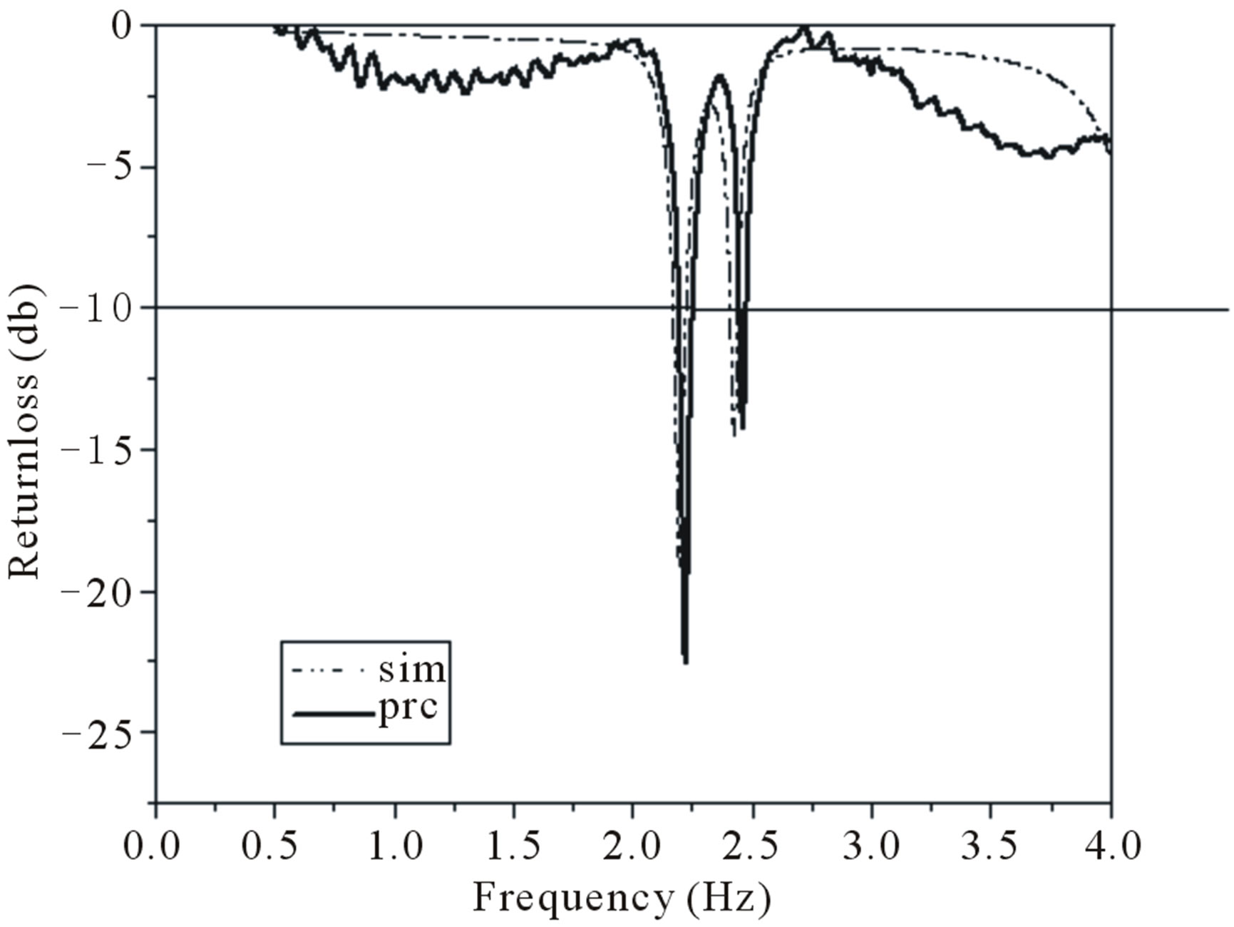
The results of all proposed antennas are shown in Table 2. The simulated and measured return loss characteristics of proposed antennas are shown from Figures 7(a)- (d).
From the results it is clear that the resonant frequency of the antenna 1 i.e., modified base antenna with slot is fr = 1.27 GHz which is lower compared to the base antenna without slot (fr = 2.199 GHz). So the size reduction obtained is 66.85%. The antenna 2 i.e. the modified antenna with slots and first iteration gives multiple bands with lower frequency of 0.99 GHz. The size reduction obtained for antenna 2 is 79.88%. Further antenna 3 i.e., with slot and second iteration gives multiple bands with
 (a)
(a)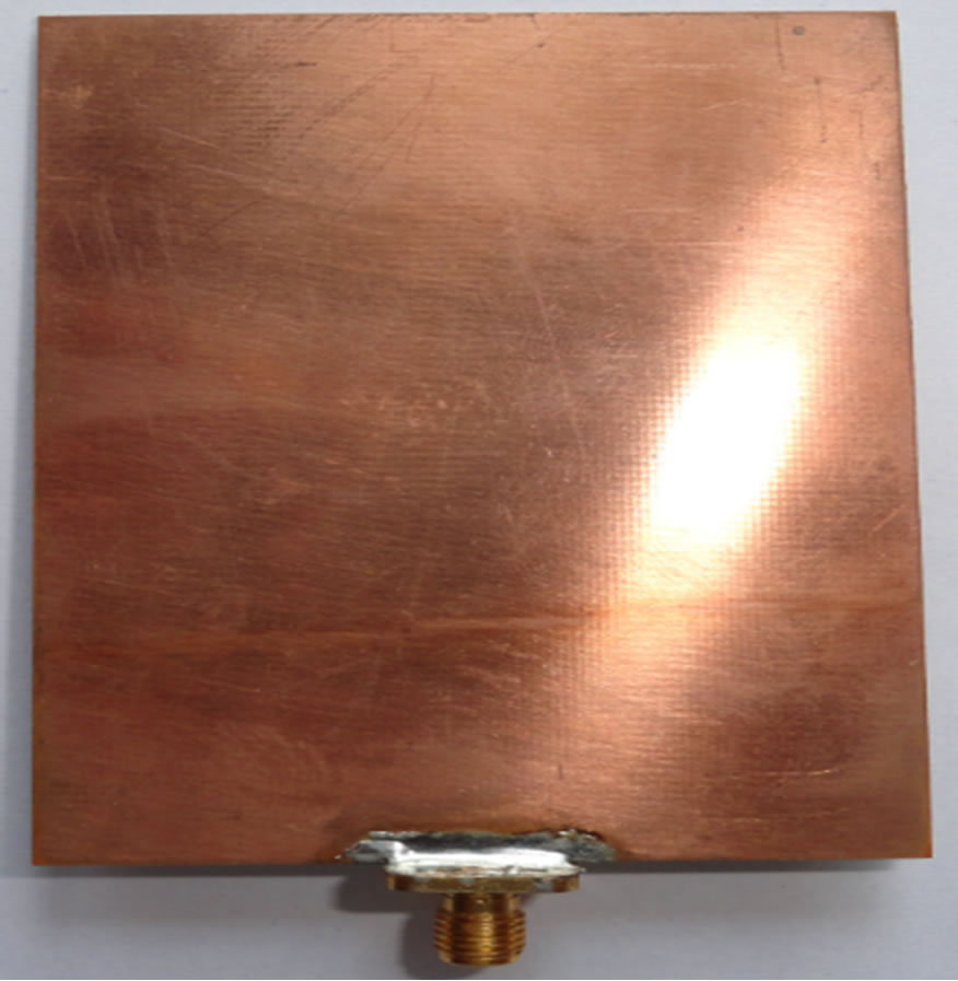 (b)
(b)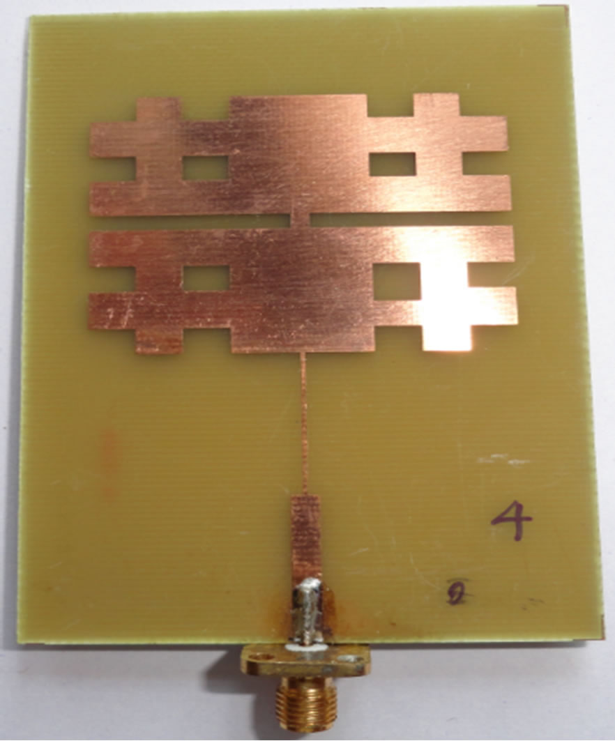 (c)
(c)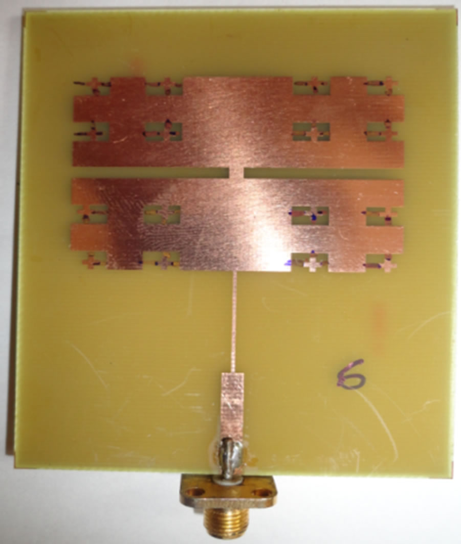 (d)
(d)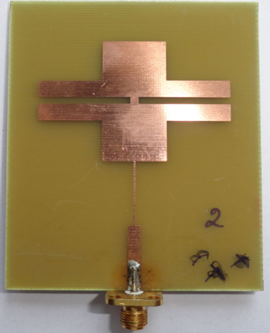 (e)
(e)
Figure 5. (a) Photograph of top view of base antenna; (b) Photograph of bottom view of base antenna; (c) Photograph of antenna 1; (d) Photograph of antenna 2; (e) Photograph of antenna 3.
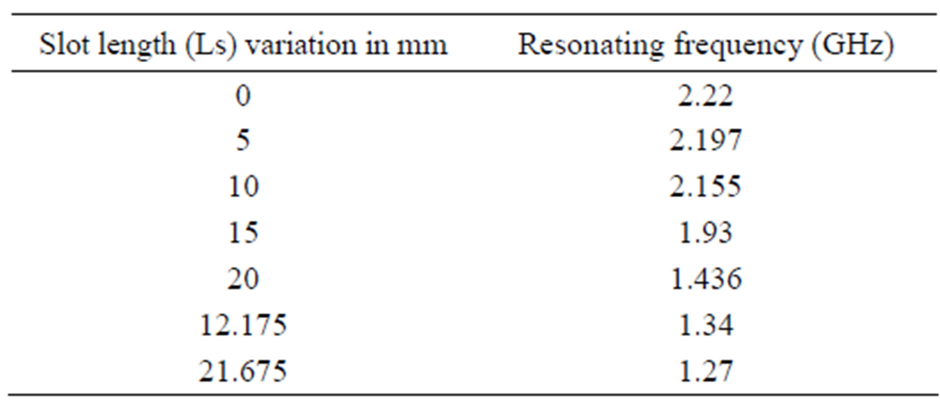
Table 1. Variation of slot length v/s resonant frequency.
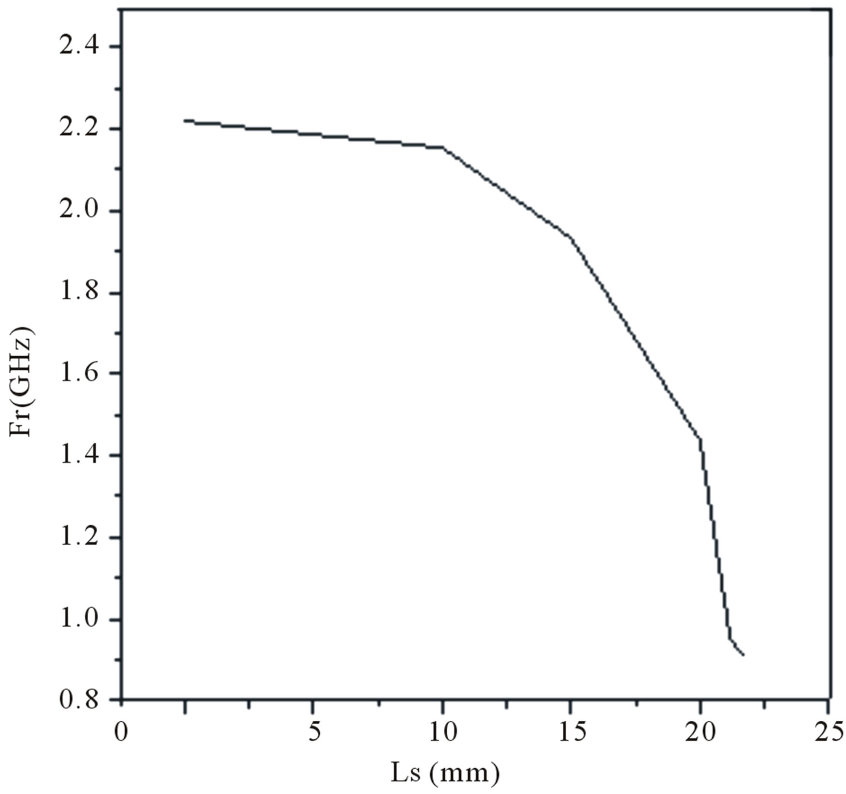
Figure 6. Variation of resonant frequency v/s slot length.
lower resonant frequency of 0.90 GHz. The size reduction obtained for antenna 3 is 81.77% which is more compared to all other proposed antennas.
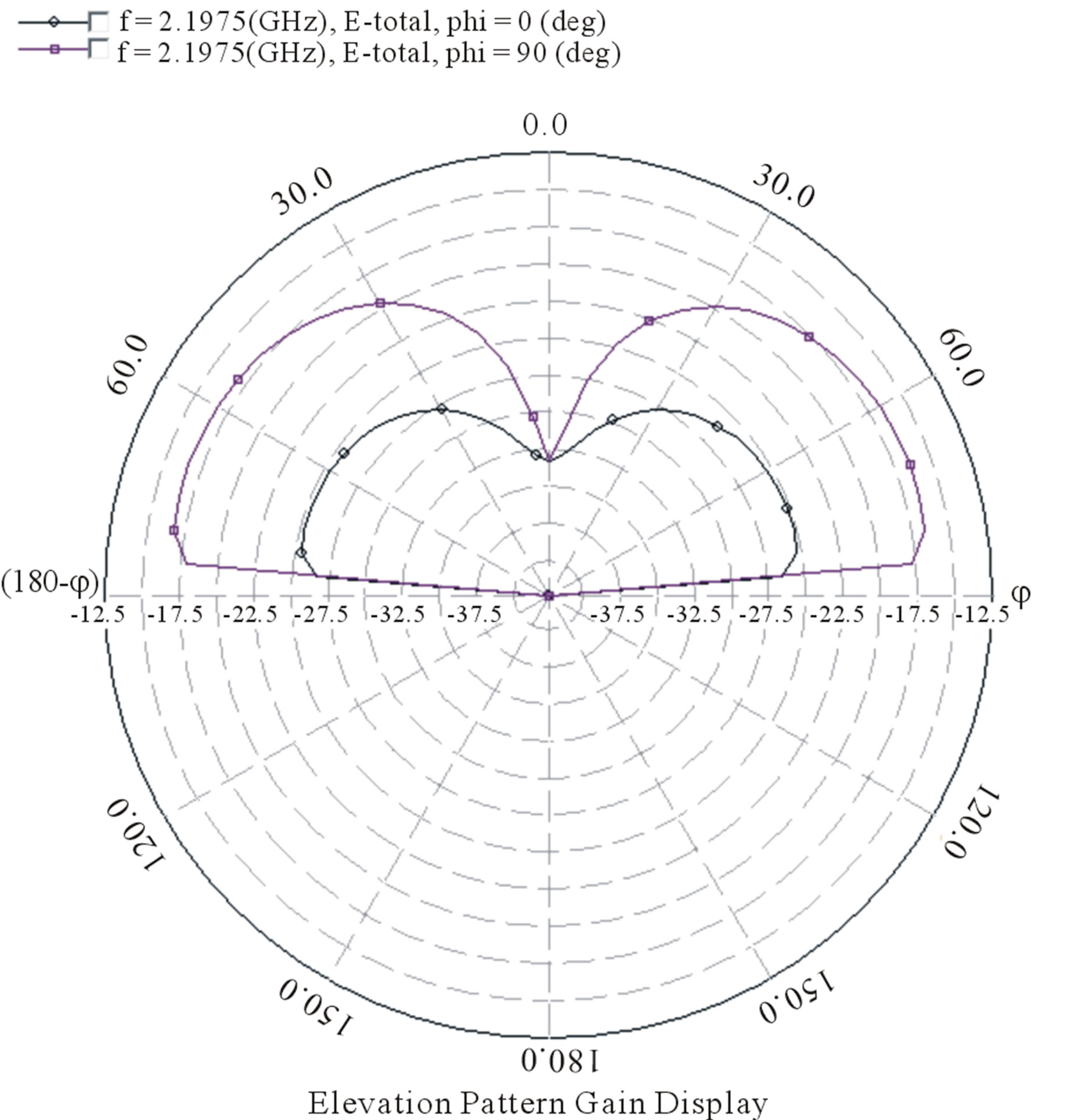
Further the bandwidths of proposed antennas have been studied through simulation and measurements and the results are shown in Table 2. From the results it is clear that the bandwidths of modified antenna with slot, first & second iteration are more compared to base antenna. The measured bandwidth of antenna 1 is 106 MHz (4.895%), antenna 2 is 190 MHz (11.93%) and antenna 3 is 215 MHz (12.92%). The radiation patterns of all proposed antennas are studied and all are giving broadside radiation. Splitting of beam i.e. dip is found in Figure 8(a) of simulated radiation pattern of base shape at 2.19 GHz. In Figure 8(b) splitting of beams merged into broadside pattern at 0.91 GHz at second iterations this results into broadside radiation pattern.
4. Conclusion
This paper presents a new plus shape slotted fractal antenna with first and second iterations. The antenna.3 i.e., slotted fractal antenna with second iteration gives size reduction of 81.77% and band width of 12.92% with broad side radiation pattern. So from the results we conclude that the modified base antenna with slots of second iterations gives a good size reduction and enhanced band width compared to that of modified base antenna with
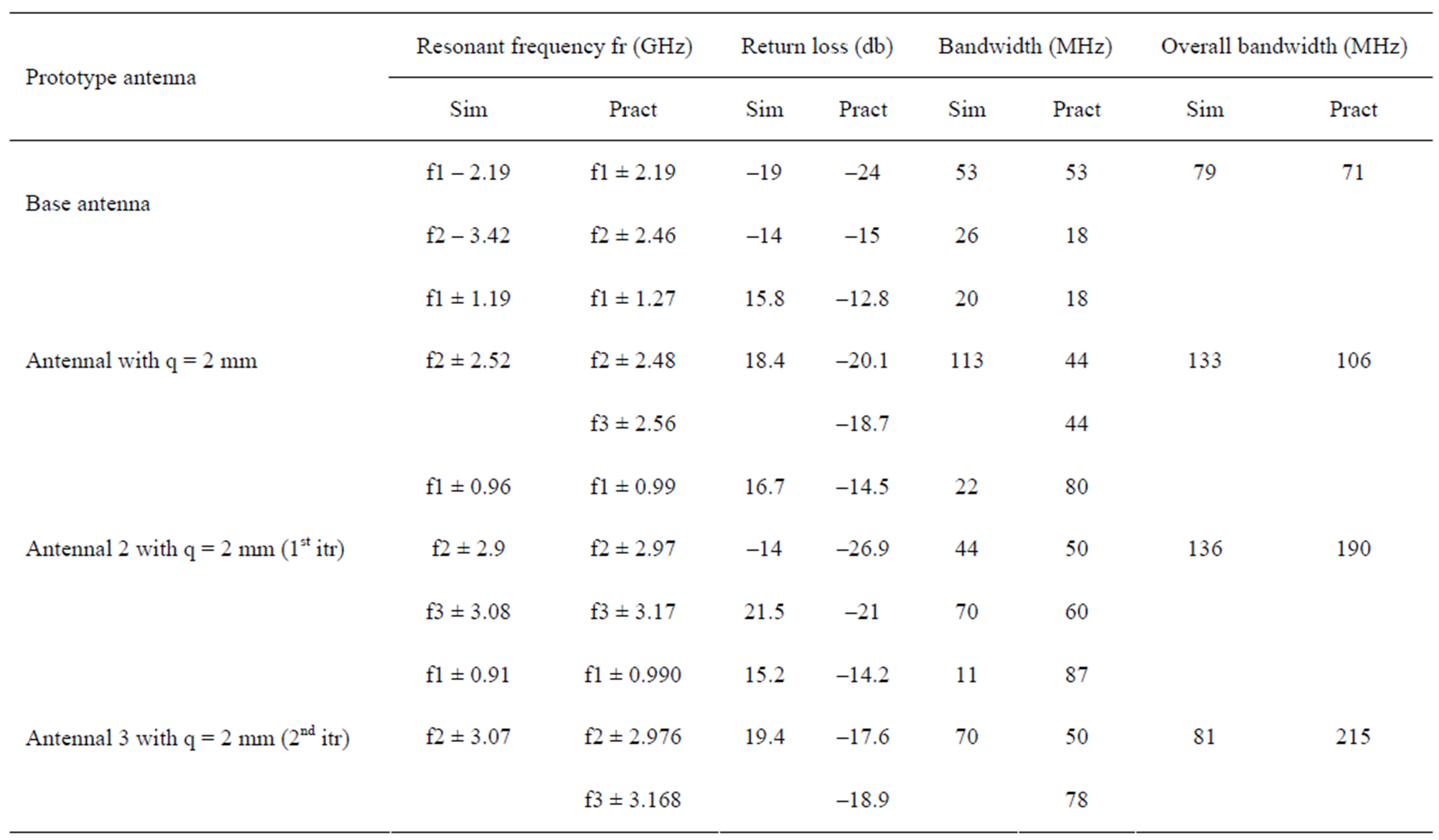
Table 2. Results of proposed antennas.
 (a)
(a)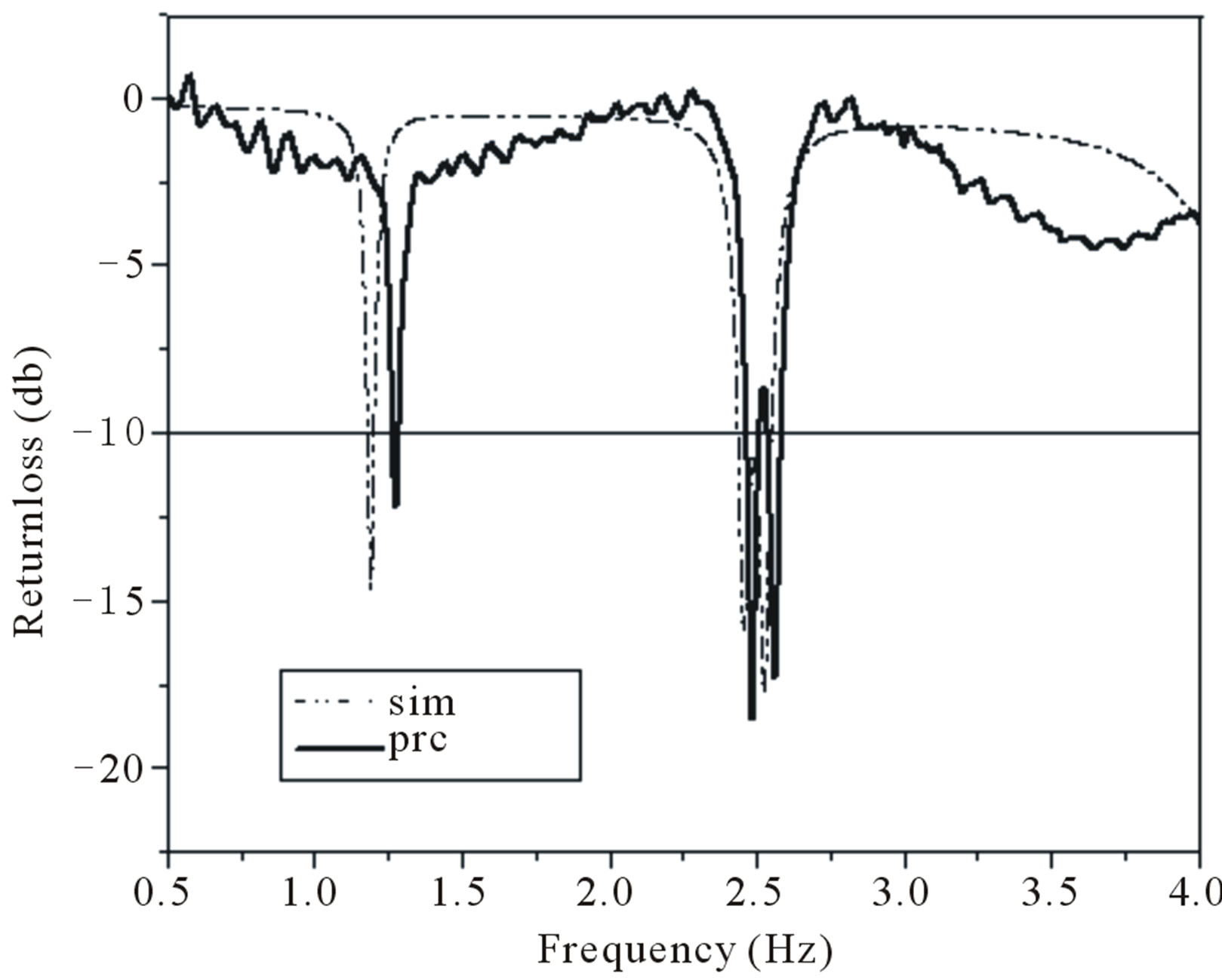 (b)
(b) (c)
(c)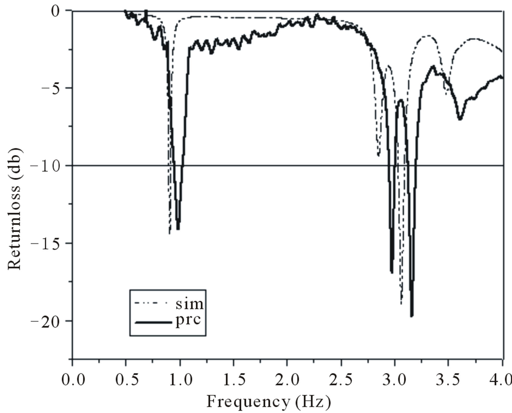 (d)
(d)
Figure 7. (a) Return loss characteristic of antenna 1 with q = 2 mm; (b) Return loss characteristic of base antenna 2 with q = 2 mm; (c) Return loss characteristic of antenna 2 with q = 2 mm; (d) Return loss characteristic of antenna 3 with q = 2 mm.
 (a)
(a)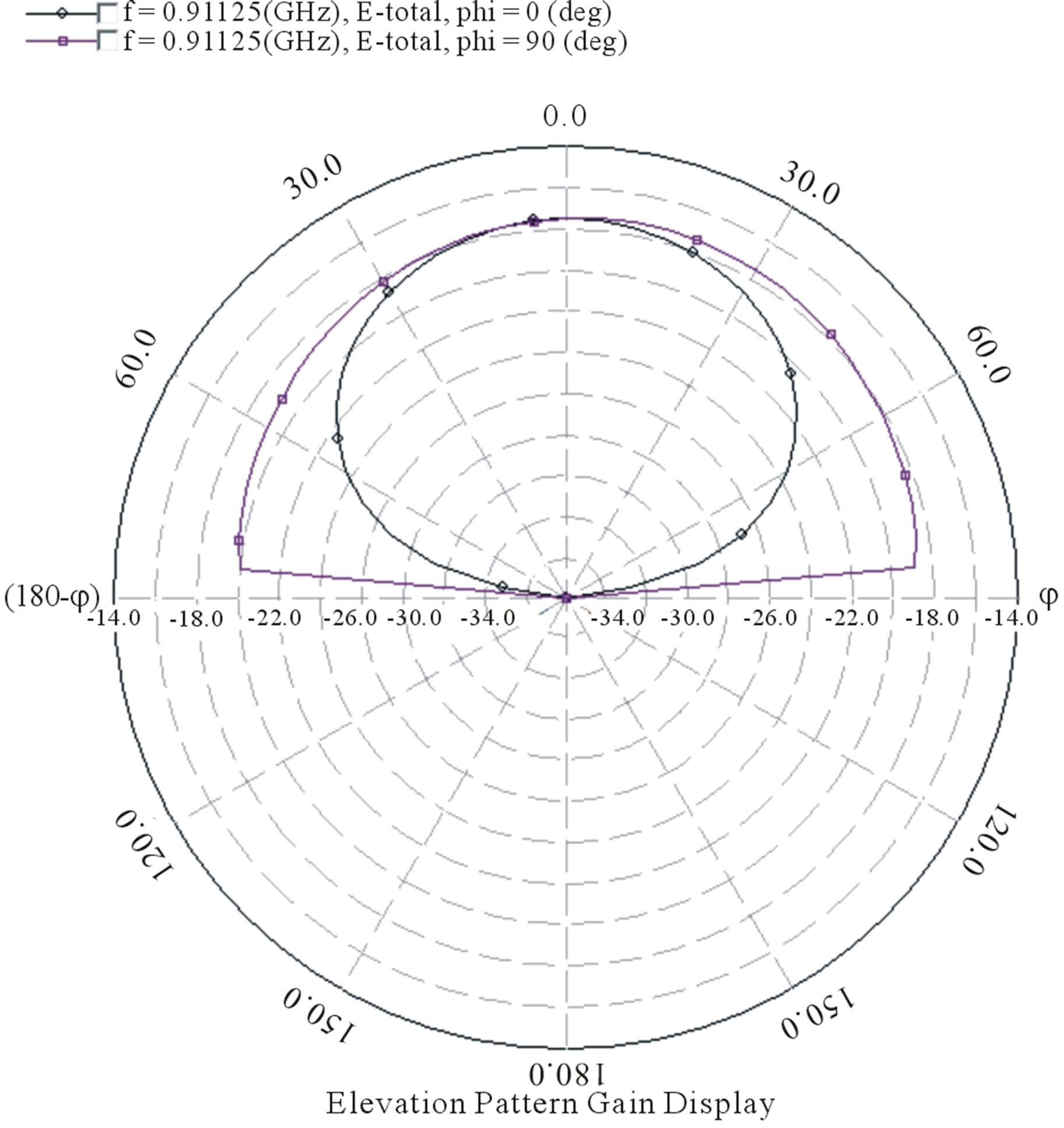 (b)
(b)
Figure 8. (a) Simulated radiation pattern of base shape at 2.19 GHz; (b) Simulated radiation pattern at 0.91 GHz for second iteration.
slot of first iteration. These antennas may find application in wireless communication systems.
REFERENCES
- K. Sing, V. Grewal and R. Saxena, “Fractal Antennas: A Novel Miniaturization Technique for Wireless Communications,” International Journal of Recent Trends in Engineering, Vol. 2, No. 5, 2009, pp. 172-176.
- B. Mandelbrot, “Fractal: Form, Chance and Dimension,” W. H. Freeman and Company, San Francisco, 1997.
- H. O. Peitgzen, H. Jurgens and D. Sanpe, “Chaos and Fractals,” New Frontiers in Science, Springer-Verlag, New York, 1992.
- C. Punete, J. Romen, R. Pous, X. Garkia and F. Beitez, “Fractal Multiband Antenna Based on the Serpinski Gasket,” Electronics Letters, Vol. 32, No. 1, 1996, pp. 1-2. doi:10.1049/el:19960033
- J. P. Gianvittorio and Y. Rahmat-Sami, “Fractal Antennas: Novel Antenna: A Novel Antenna Miniaturization Technique and Applications,” IEEE Antenna and Propagation Magazine, Vol. 44, No. 1, 2002, pp. 20-36. doi:10.1109/74.997888
- D. H. Werner and S. Ganguly “An Overview of Fractal Antenna Engineering Research,” IEEE Antenna and Propagation Magazine, Vol. 45, No. 1, 2003, pp. 38-57.
- G. Srivatsun, S. S. Rani and G. S. Krishnan, “A SelfSimilar Fractal Cantor Antennas for MICS Based Wireless Applications,” Wireless Engineering Technology, Vol. 2, No. 2, 2011, pp. 107-111. doi:10.4236/wet.2011.22015
- W. Shalan and K. Pahwa, “Multiband Microstrip Rectangular Fractal Antenna for Wireless Applications,” International Journal of Electronics Engineering, Vol. 3, No. 1, 2011, pp. 103-106.
- F. J. Jibrael and M. H. Hammed, “A New Multiband Patch Microstrip Plusses Fractal Antenna for Wireless Applications,” ARPN Journal of Engineering and Applied Sciences, Vol. 5, No. 8, 2010, pp. 155-158.