Journal of Environmental Protection
Vol.5 No.4(2014), Article ID:44128,6 pages DOI:10.4236/jep.2014.54035
Acoustical Design of an Electrical Emergency Plant Using Sea Method
Evgeny Podzharov1, José F. de la Mora Gálvez2, Jesus A. Alvarez Sanchez1
1Electromechanical Engineering Department, University of Guadalajara, Puerta 10, Guadalajara, México
2Superior School of Engineering Prolongacion Calz, University of Panamericana, Circunv. Pte 49, Guadalajara, México
Email: epodzhar@up.edu.mx, fmora@up.edu.mx, jaas2001@yahoo.es
Copyright © 2014 by authors and Scientific Research Publishing Inc.
This work is licensed under the Creative Commons Attribution International License (CC BY).
http://creativecommons.org/licenses/by/4.0/


Received 12 January 2014; revised 13 February 2014; accepted 11 March 2014
ABSTRACT
The statistical energy analysis (SEA) was used in the acoustical design of an electrical emergency plant to reduce the outdoor noise level. In the past, when the plant was working, a high annoying noise was heard all over the university camp. At a first glance the principal ways of noise propagation were the open door of the plant which was used for the suction of fresh air and a vast hole in the ceiling which was used for gases outlet. Also, a spectral analysis of the noise inside the plant showed that the dominant frequencies of the noise were in the range of 120 - 270 Hz. This frequency range is near the critical frequency of the brick walls that is 129 Hz, at which the walls are transparent for noise. A two-block diagram is used for the statistical energy analysis. Two ways of sound transmission are considered through the inlet and outlet holes and through the walls and ceiling. This analysis shows that the exclusion of holes wouldn’t be sufficient to reduce noise to an acceptable level in a low frequency range but increase the noise absorption by the wall coating material. The transmission loss is calculated for different wall coatings and hole areas. A layer of fiberglass of two-inch width is selected to increase the wall absorption coefficient. Special silencers are designed and put at the suction of air and at the outlet of engine gases to reduce the noise propagation through the holes. The noise measurement shows that the noise level is considerably reduced after implementation of these measures. The reduction of noise is 7 - 8 dB (A), 19 dB (A) and 23 dB (A), inside the plant, 10 m and 15 m away from the plant, respectively.
Keywords:Noise Reduction of an Elictric Plant; Statistical Energy Analysis; Transmission Loss; Spectral Analysis; Absoption of Noise

1. Introduction
The noise contamination in the cities is an important problem nowadays as the cities become more populated and there are more vehicles on the streets. One part of the problem is the noise in studying and working areas as well as in the residential areas.
In the University of Panamericana in Guadalajara, Mexico, there is an electrical emergency plant which supplies electricity for the campus during the electricity cut-offs in the summer during the rainy season. The plant has a diesel engine and electric generator which are installed inside a small building. This engine was producing a very loud noise which was heard all over the university campus and was the cause of many complaints by students and professors.
2. Noise Measurements and Its Analysis
The results of the noise measurements inside and outside of the plant are shown in Figure 1. The noise level inside the plant is very high (112 dBA). It decreases 13 dBA passing the open door of the plant. Then it decreases slowly till 72 dBA at 25 m from the source being still high. The measurements in the offices and the class rooms of the building nearer to the plant showed noise levels from 59 dBA to 69 dBA which are all beyond the permissible noise level.
The noise spectrum inside the plant shows (Figure 2) that the majority of noise’s components are in low fre-
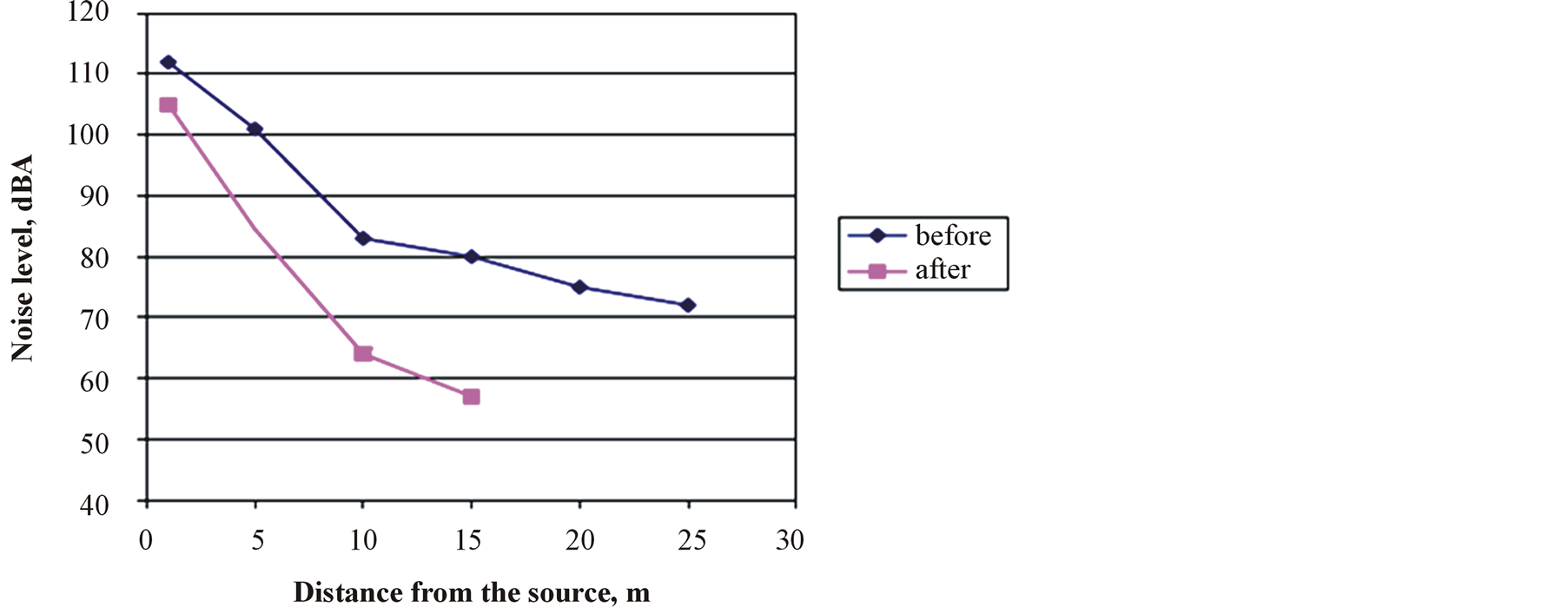
Figure 1. Noise level inside and outside of the plant.
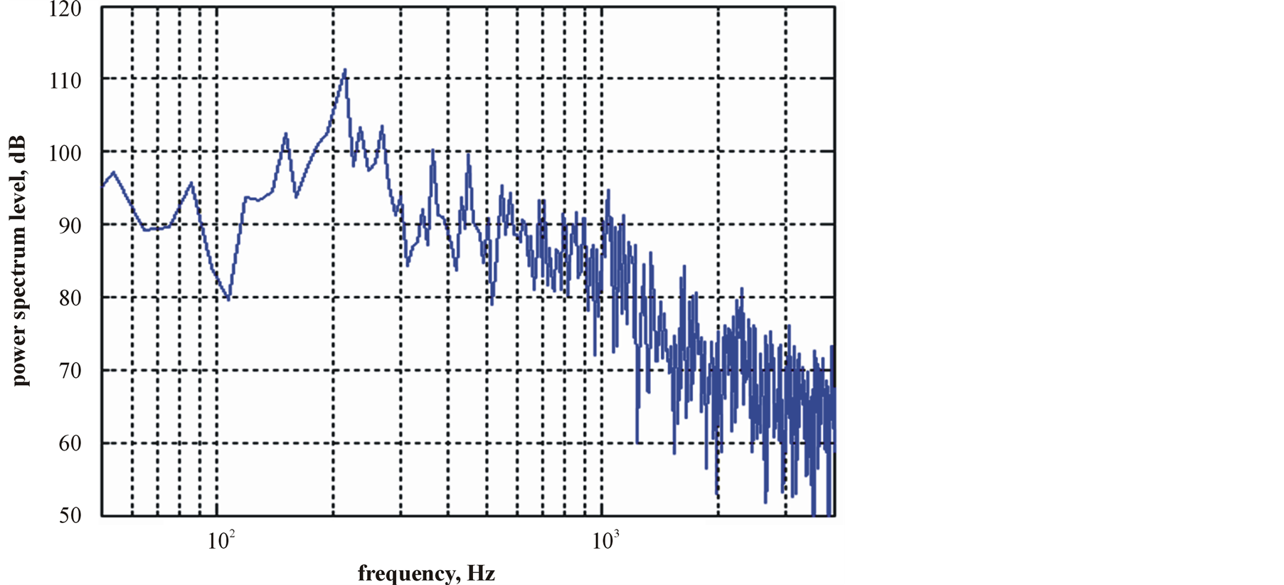
Figure 2. Noise spectrum measured inside of the plant.
quency range near 200 Hz; meanwhile there are also high level components in the middle frequency range up to 1200 Hz and in higher frequencies.
3. Analysis of the Plant Acoustical System Using Sea Method
The principle ways of noise propagation must be studied to reduce effectively the noise level. The noise radiated by the machine towards the internal acoustical space inside the plant goes out to the external acoustical space by three ways: 1) through the entrance door and the exhaust hole in the ceiling, 2) through the walls, 3) through the foundation. The third way can be considered insignificant because the machine is properly vibroisolated from the foundation.
To realize the acoustical analysis of the plant by the SEA method an acoustical model in Figure 3 can be used.
Where E1—acoustical energy of the internal acoustical space, J E2—acoustical energy of the external acoustical space, J W in—acoustical power introduced by the machine, W
 —acoustical power dissipated in the element i of the model, which can be determined using the following equation [1]
 , (1)
, (1)
Where
ηi—loss factor of element iω = 2πf—angular frequency, rad/s f—frequency, Hz.
 —acoustical power transmitted through the walls and ceiling, W
 —acoustical power transmitted through the door and the air duct in the ceiling, W According to [1] [2] the equation of energy balance can be written as follows

 . (2)
. (2)
Here
 (3)
(3)
Where
ηij—transmission loss factor between elements i and j.
Substituting Equation (3) into Equation (2) and then into Equation (1) and considering that acoustical energy transmission is insignificant in the inverse direction, as , the equation of energy balance can be obtained in the following form
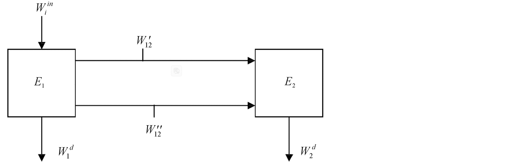
Figure 3. Acoustical model of the plant.
 , (4)
, (4)
 .
.
Now, dividing the first equation of (4) by the second, we have
 (5)
(5)
The acoustical energy transmitted through the holes must be proportional to the relation
 , where
 —the total area of the holes,
 —the total area of the walls and the ceiling.
So the coefficient  can be found from the equation
 (6)
(6)
When , Equation (6) can be transformed into the equation
 (7)
(7)
Substituting Equation (7) in Equation (5), we have
 (8)
(8)
The attenuation of machine noise by the walls and the ceiling can be found as
 (9)
(9)
where
η1—loss factor of the absorption of the noise by the walls, the ceiling and the floor, it can be accepted equal to absorption coefficients of materials [3] .
According to [1]
 , (10)
where c—sound velocity in airτ = 10−TL/10—Transmission loss factorTL—transmission lossV1—volume of the internal acoustical space, m3
f—sound frequency, Hz.
The transmission loss depends on the sound frequency and the critical frequency fc of the walls [2] ,
 , (11)
Where cL—velocity of longitudinal waves in the barrier (walls, ceiling), m/s t—barrier width, m.
For the walls and ceiling of bricks with t = 0.15 m and fc = 129 Hz, cL = 3400 m/s, c = 344 m/s.
When f < fc the mass law actuates and

when 

when 
 (12)
(12)
where ρ—air density, kg/m3
ρS—unit area density, kg/m2
ηW—walls dissipation coefficient ( for bricks ηW = 0.01).
The total area of the walls and ceiling of the plant is A = 110.5 m2, the volume V1 = 110.05 m3. The area of the holes was estimated as A = 3 m2.
The attenuation of sound is calculated using Equations (10) - (14). The results of these calculations are presented in Figure 4. The curve 1 corresponds to the initial conditions. It gives only 15 dB except the zone of critical frequency where the attenuation falls till 5 dB. This almost coincides with the results of noise measurements (Figure 1). The reduction of the area of holes up to 1 m increases the attenuation by 5 dB except in the critical frequency (curve 2). For further increase of the attenuation, two silencers for the suction and exhaust holes were designed and fabricated. The silencers are of absorbing type and were designed using fiberglass and perforated steel sheets.
The attenuation of sound in silencers can be estimated [4] [5] using this equation:
 (13)
(13)
where l—longitude of silencer, m
α—absorption coefficientP—interior perimeter of the duct, m S—interior transverse area of the duct, m2.
The absolute value of this sound absorption is
 . (14)
Taking into account the silencers attenuation, Equation (9) will transform in the following
 (15)
(15)
Using Equation (17) curve 3 and 4 in Figure 4 is calculated. As we see from Figure 4 the introduction of silencers reduces the noise very much except in the critical frequency. For reducing the noise in the critical frequency and overall, the walls and the ceiling are covered with fiberglass of 2 inch thick (curve 4 in Figure 4).
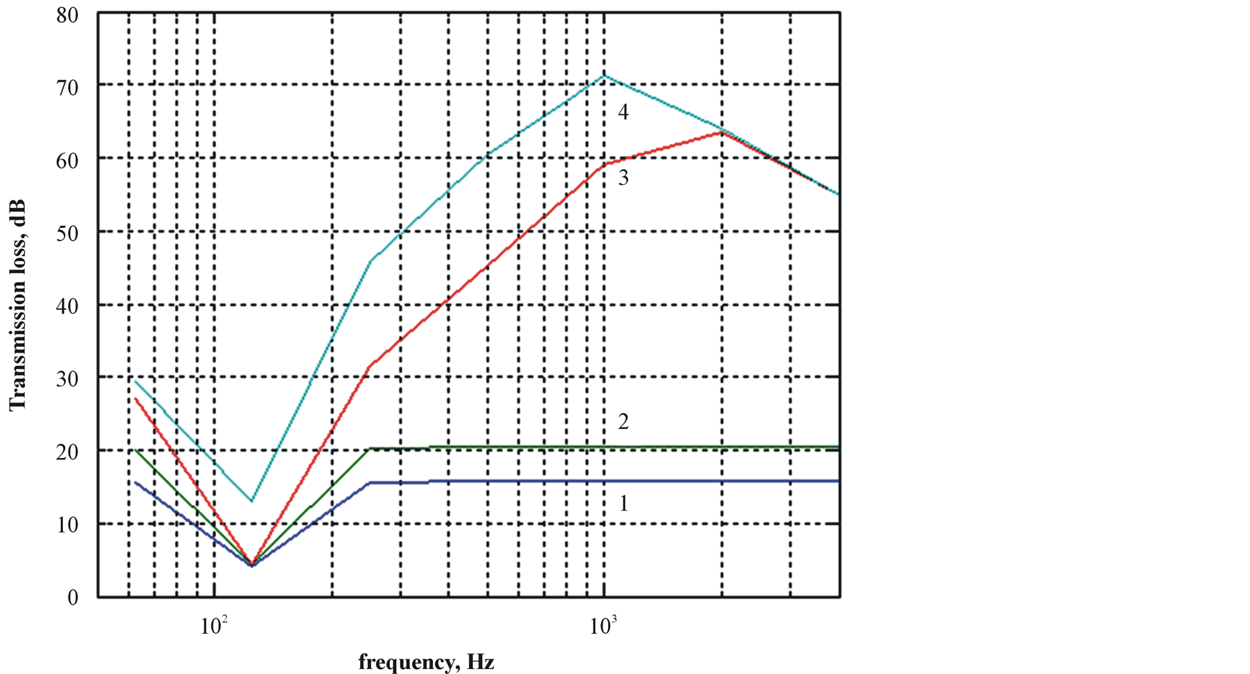
Figure 4. Sound transmission loss for different conditions: 1—initial conditions with the holes of 3 m2, 2—the holes area reduced till 1 m2, 3—the silencers are installed, 4—the silencers are installed and the walls and ceiling are covered with fiberglass of 2 inch thick.
In Figure 1 the effect of this vibroacoustical design in the reduction of noise level of the plant is presented. It can be seen that the noise level is reduced by 23 dBA at the distance of 15 m away from the source. Now the noise of the plant in the working area is so low that it is practically not heard.
4. Conclusions
1) The noise measurements of the plant in the university campus show that the noise level exceeds the permissible levels in the offices and classrooms.
2) An analysis of the acoustical system of the plant using the SEA method shows that the walls and the ceiling don’t have enough transmission loss because of vast holes at the suction of air and at the exhaust.
3) The reduction of the hole areas from 3 m2 to 1 m2 does not give a sufficient reduction of the noise.
4) By using fiberglass coatings for the walls and ceiling and especially designed silencers, a sufficient reduction of noise level (23 dBA at the distance of 15 m from the source) is achieved.
References
- Lion, R. (1975) Statistical Energy Analysis. Theory and Applications. The MIT Press, Cambridge and London.
- Leo, L. and Beranek, I.L.V. (1992) Noise and Vibration Control Engineering. Principles and Application. Wiley & Sons, Inc., New York.
- Cyril, M.H. (1995) Manual de Medidas Acústicas y Control del Ruido. Tercera Edición. McGraw-Hill, New York.
- Faulkner, L.L. (1975) Handbook of Industrial Noise Control. Industrial Press Inc., South Norwalk.
- Lewis, H.B. and Douglas, H.B. (1994) Industrial Noise Control. Fundamentals and Applications. 2nd Edition. Marcel Dekker, Inc., New York.