Smart Grid and Renewable Energy
Vol. 4 No. 1 (2013) , Article ID: 28131 , 7 pages DOI:10.4236/sgre.2013.41010
A Power Electronic Conditioner Using Ultracapacitors to Improve Wind Turbine Power Quality
![]()
1Electrical & Computer Engineering, Missouri University of Science & Technology, Rolla, USA; 2Geological Engineering, Missouri University of Science & Technology, Rolla, USA; 3Wind Energy Technologies, Sandia National Laboratories, Albuquerque, USA.
Email: *crow@mst.edu
Received November 14th, 2012; revised December 14th, 2012; accepted December 30th, 2012
Keywords: Power Electronics; Electrochemical Capacitors; Ultracapacitors; Wind Power
ABSTRACT
The large variability in wind output power can adversely impact local loads that are sensitive to poor power quality. To mitigate large swings in power, the wind turbine output power can be conditioned by using a small energy buffer. A power conditioner is developed to smooth the wind power output by utilizing the energy of an electrochemical capacitor, or ultracapacitor. The conditioner is based on a single phase voltage source inverter connected between the grid interconnection point and the ultracapacitor. The VSI shunt inverter injects or absorbs active power from the line to smooth the wind power output by utilizing the short term storage capabilities of the ultracapacitor. The ultracapacitor is connected to the DC link through a bidirectional DC-DC converter. The bidirectional DC-DC converter and VSI are constructed and field tested on a Skystream 3.7 wind turbine installed at the Missouri University of Science & Technology.
1. Introduction
Due to the price volatility and carbon impact of fossil fuels, wind power generation is rapidly growing as an alternative energy source in many parts of the world. Due to the intermittency of wind speed, wind turbine output power can be highly variable. Power fluctuations from the wind turbine may cause severe power quality problems when connected to the grid. The large variability in wind turbine output power can adversely impact local loads that are sensitive to pulsating power, posing a challenge to the use of wind power extensively. The rapid growth of the wind power and its immense potential as a future energy source encourage us to find a way to smooth the intermittent wind power. Energy storage technologies can be used to improve the quality of the wind power [1,2]. In this paper, a power quality conditioner with the ultracapacitor is proposed to smooth the variable wind turbine output power. The short term storage capabilities of the ultracapacitor can be effectively used to smooth the wind power to minimize rapid power excursions that may damage sensitive local loads.
Ultracapacitors (also known as supercapacitors) have been proposed as a short term energy storage mechanism to provide improved active power output performance for wind turbines [3-7]. All of these articles address the application of ultracapacitors to three-phase wind turbine systems and none of them present actual experimental results for their designs. In [3], the authors present an approach to use ultracapacitors as part of the converter system for a Doubly Fed Induction Generator (DFIG) wind turbine to smooth the output during normal operation and to provide active power support to the DFIG during low-voltage conditions. They propose a fuzzylogic rule based system to determine the charging modes of the UCAP system. In [6], the authors present an indepth simulation analysis of the ultracapacitor charge and discharge capabilities to provide a procedure for sizing an ultracapacitor storage system. The authors in [5] use a state-space-based model of a permanent magnet synchronous generator coupled with blade-pitch control as the wind turbine model. The emphasis of this paper was to study the detailed behavior of the wind turbine as opposed to the characteristics of the ultracapacitor behavior.
The power conditioner mainly consists of power converters to shape the injected current at the point of common coupling [8]. The conditioner is based on a single phase shunt connected VSI connected between the grid interconnection point and the ultracapacitor. The shunt VSI injects or absorbs active power from the line to smooth the intermittent wind power by charging or discharging the ultracapacitor [9]. The ultracapacitor is connected to the DC link through a DC-DC converter. Traditionally, the VSI DC link voltage is maintained relatively constant by the shunt inverter control. In this application, we use a bidirectional DC-DC converter to maintain the DC link voltage. The bidirectional DC-DC converter acts in buck mode during discharge of the DC link and in boost mode during charging to maintain the voltage of the DC link to provide good controllability of the VSI.
Control of the injected active power via the shunt inverter is presented in this paper. The VSI controller calculates the compensating active power, which is then synthesized by using the bipolar pulse width modulation (PWM) switching sequence. The reference signal to the shunt inverter controller is obtained from a low pass filter, which has a large time constant. The fluctuating wind power is passed through the low pass filter to get the smoothed reference value. The conditioner ensures the smooth power is available at the grid interconnection point. The simulation results are presented to show the efficiency of the conditioner in smoothing the variable wind turbine output power.
2. The Wind Turbine
The power conditioner design and control will be validated on the Skystream3.7 wind turbine installed at the Missouri University of Science and Technology. The installed wind turbine is shown in Figure 1. The wind turbine is rated 2.4 kW at a wind speed of 29 mph with a cut-in wind speed of 8 mph. The three rotor blades have a 12 ft spinning diameter. The wind turbine alternator is a slotless permanent magnet brushless motor with passive yaw control. The Skystream3.7 wind turbine output is 120/240 VAC Split single phase, 60 Hz and is connected to the campus grid as shown in Figure 2.
The neutral and ground terminals of the wind turbine are tied together and connected to the neutral of the grid. The power quality conditioner is connected in shunt between the output of the wind turbine and the grid interconnection point.
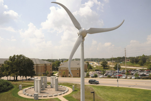
Figure 1. Skystream3.7 wind turbine used for experimental validation.
3. The Power Conditioner
As shown in Figure 3, the power quality conditioner consists of a shunt inverter and a bidirectional DC-DC converter. The voltage source inverter acts as a shunt active filter compensating the active power of the wind turbine. The VSI is connected to the line through an RL filter which reduces the unwanted harmonics. The shape of the output current of the conditioner depends on the inductor value. The value of the resistor and the inductor determines the damping in the circuit. On the other side, the VSI is connected to the DC link capacitor. The DCDC converter with the ultracapacitor is used to reduce the size of the DC link capacitor and to maintain the voltage of the DC link relatively constant as the ultracapacitor discharges and charges. The bidirectional DC-DC converter charges the ultracapacitor in buck mode by reducing the voltage of the DC link. In the other direction, it acts in boost mode, discharging the ultracapacitor to increase the voltage of the DC link. The power conditioner injects or absorbs active power from the line through the filter to smooth the variable wind turbine output power. The DC link acts as the voltage source for the VSI.
The primary objective of the conditioner is to inject a current Iinv at the point of common coupling (PCC) such
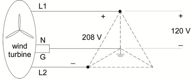
Figure 2. Skystream3.7 wind turbine connection to the grid.
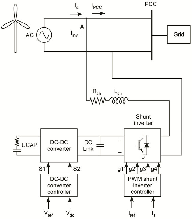
Figure 3. Power quality conditioner.
that the current supplied to the grid (IPCC) is relatively smooth. The smoothed current is obtained by passing the (measured and scaled) wind turbine current through a low pass filter that is tuned to provide the appropriate high-frequency cutoff. The ultracapacitor is charged and discharged rapidly to supply the required current while holding the DC link constant. Note that the reference current is not a constant, but rather a slowly varying current. If the reference current were held constant, this would imply that the electrochemical capacitor would have infinite ability to charge and discharge. By allowing the reference current to slowly vary, the energy supplied to the grid will track the energy supplied by the wind turbine.
3.1. The DC-DC Converter
The three primary components of the proposed power conditioner are the shunt inverter to control the injected current, the ultracapacitor, and the DC-DC converter to regulate the DC link voltage and control the ultracapacitor injected current. The topology of the bidirectional DC-DC converter is shown in Figure 4. The bidirectional DC-DC converter acts a buck converter in one direction and as a boost converter in the other direction [10-13]. Power MOSFETS are used as the switching devices in the circuit. The operation of the converter is controlled by the DC link voltage and the voltage of the ultracapacitor. The main purpose of the bidirectional DC-DC converter is to maintain the voltage of the DC link relatively constant at a reference value. The 2200 mF DC link capacitor is used as an intermediate element between the DC-DC converter and the inverter.
The DC-DC converter operating modes can be divided into four modes:
• Mode 1: The DC-DC converter acts in buck mode when the DC link voltage  is greater than the reference value
 . In this mode, the DC-DC converter controls the current to charge the ultracapacitor.
• Mode 2: The DC-DC converter acts in boost mode when the DC link voltage  falls below the reference value. In this mode, the ultracapacitor discharges.
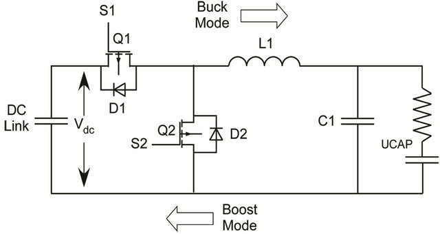
Figure 4. DC-DC converter.
• Mode 3: When the ultracapacitor is fully charged, the DC-DC converter shuts down to avoid damaging the ultracapacitor.
• Mode 4: When the ultracapacitor is fully discharged, the conditioner shuts down until the wind turbine produces sufficient current to resume charging of the ultracapacitor.
The bidirectional DC-DC converter shown in Figure 5 was constructed from IXFK80N50P power MOSFETS as the switching devices in the circuit. The Microchip PIC24FJ128GA010 microcontroller along with the Explorer16 development board was used in implementing the control scheme and to obtain the gate signals for the MOSFETs in the bidirectional DC-DC converter. LEM LV 25-P voltage sensors are used to measure the voltages of the DC link and the ultracapacitor. The ACNW3190 5.0 Amp High Output Current Gate Drive optocoupler is used to drive the MOSFETs. A TP-75C DC power supply is used to supply power to the LEM sensors and gate drivers. The voltage measurement circuits and the gate driver circuits are built on the vector board and are soldered permanently. The high current inductor used in the circuit is manufactured by West Coast Magnetics.
3.2. The Ultracapacitor
Ultracapacitors are electrochemical double layer capacitors that have unique characteristics when compared to other energy storage devices. Ultracapacitors (UCAPS) have high energy density and large time constants as well. Although multiple time-scale models of UCAPs have been developed, a simple UCAP model such as the one in Figure 3 containing only one RC branch was used in the simulation of the converter system. This model is composed of an equivalent series resistor (ESR) and a
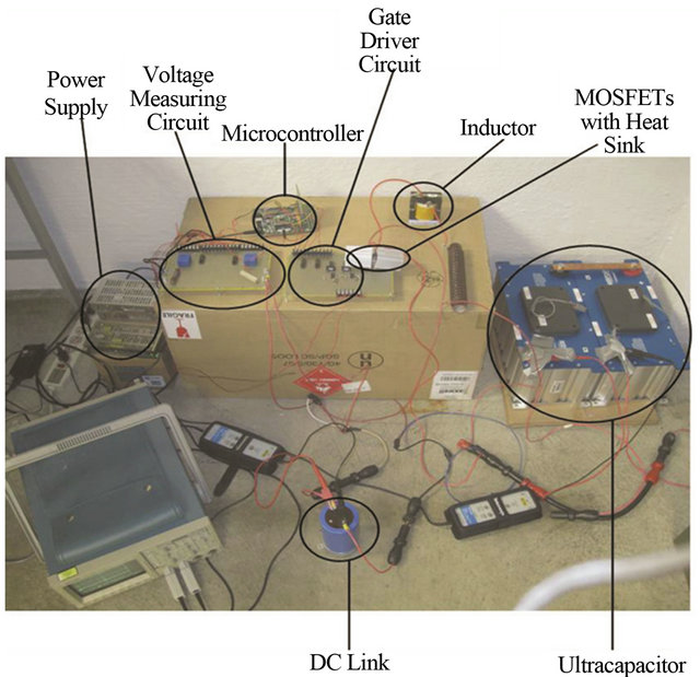
Figure 5. DC-DC buck-boost converter experimental hardware.
capacitor (C) [10]. The ESR represents the ohmic losses in the ultracapacitor. Higher order ultracapacitor models are essential for simulation studies in which the timescale of interest is on the order of microseconds. In the current application, the timescale of interest is on the order of minutes; therefore the single RC branch model is sufficient to capture the UCAP behavior of interest.
The benefits of using ultracapacitors are quite extensive. Ultracapacitors have low losses while charging and discharging. They have a very low ESR, allowing them to deliver and absorb very high currents and to be charged very quickly, making them well suited for energy buffer applications. Ultracapacitors are highly efficient components even at very high currents. The characteristics of the UCAP allow it to be charged and discharged at the same rates, something most batteries cannot tolerate. Ultracapacitors have a wide voltage window and can be deeply discharged. The energy storage mechanism of an UCAP is a highly reversible process. The process moves charge and ions only. It does not make or break chemical bonds like batteries; therefore it is capable of millions of cycles with minimal change in performance. It is therefore capable of many years of continuous duty with minimal change in performance. These advantages make ultracapacitors well suited for power quality conditioning applications.
The power conditioner was constructed using two series-connected Maxwell BMOD0165 ultracapacitor modules of 165F nominal capacitance and rated voltage 48.6 V. This ultracapacitor has a maximum continuous current of 77 A at 15˚C [11].
3.3. The Shunt Inverter
A full-bridge IGBT based inverter topology is used in this application. The full-bridge inverter consists of four switching devices, which are connected to form the fullbridge inverter circuit shown in Figure 6. The gating signals for the IGBTs are obtained by the pulse width modulation controller. Anti-parallel diodes are connected across the power IGBTs to protect the devices and to provide the power flow in the reverse direction [12,13]. The voltage source inverter connected in shunt to the line acts as a current source, injecting or absorbing the compensating current from the line [14]. The shunt inverter is connected to the line through a series interference RL filter, which reduces the unwanted harmonics. The filter provides smoothing and isolation from high frequency components. On the downstream side, the full-bridge inverter is connected to the DC link. The injected current is in phase with the line voltage to produce a unity power factor.
The VSI operates in the following two modes:
• Mode 1: When the wind turbine power is greater than the reference value, the converter acts like a rectifier drawing active power from the line and charging the DC link capacitor.
• Mode 2: When the wind turbine power is less than the reference value, the converter acts like a VSI injecting active power into the line by discharging the DC link capacitor.
The variable wind power is passed through a low pass filter to get a smoothing reference signal for the inverter controller. The output of the low pass filter is given to the shunt inverter controller as the reference value [15]. The reference signal  is obtained:
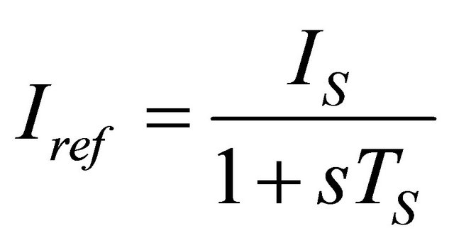 (1)
(1)
where  is the time constant of the filter and
  is the output of the wind turbine. The smoothing performance of the wind turbine output power depends on the time constant of a low pass filter. The time constant of the low pass filter is in the range of several seconds and is tuned to provide the desired smoothing. The power fluctuation is smoothed by drawing or injecting the difference of the reference power and the variable wind power.
The experimental setup and different components in the construction of the single phase shunt inverter are shown in Figure 7. A SEMIKRON SK 30 GBB 066 T IGBT module is used as the switching devices for the circuit. A 2.5 mH inductor is used as the output filter of
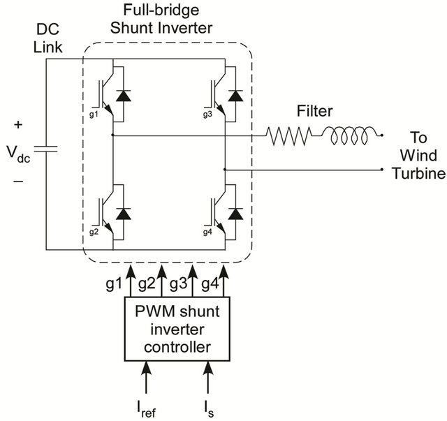
Figure 6. Shunt inverter circuit.
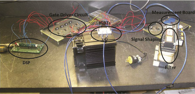
Figure 7. Shunt inverter hardware.
the shunt inverter. A TI TMDSDOCK28335 DSP is used in the closed loop control of the shunt inverter. The current and voltage sensors measures and sends signals to the DSP through the signal shaping circuit. DSP drives the IGBTS with the ACNW3190 drivers.
4. Experimental Results
Figure 8 shows the actual currents measured at the output of the wind turbine (unconditioned—thin) and at the PCC (conditioned—bold). The smoothing time constant was 60 seconds in this experiment. The average wind speeds were 15 mph and the average active power output is approximately 600 W. The corresponding voltage and current of the ultracapacitor are shown in Figures 8-10. The ultracapacitors were initially charged to a mid-range voltage of approximately 50 V to provide sufficient charge and discharge capabilities. Note that when the wind turbine current exceeds the desired (smoothed) current, the ultracapacitor will absorb the excess current (i.e. charge) and the voltage will increase. These results indicate that the conditioner is working as designed under normal operating conditions.
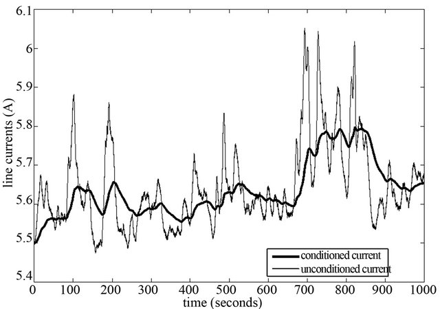
Figure 8. Line currents (measured).
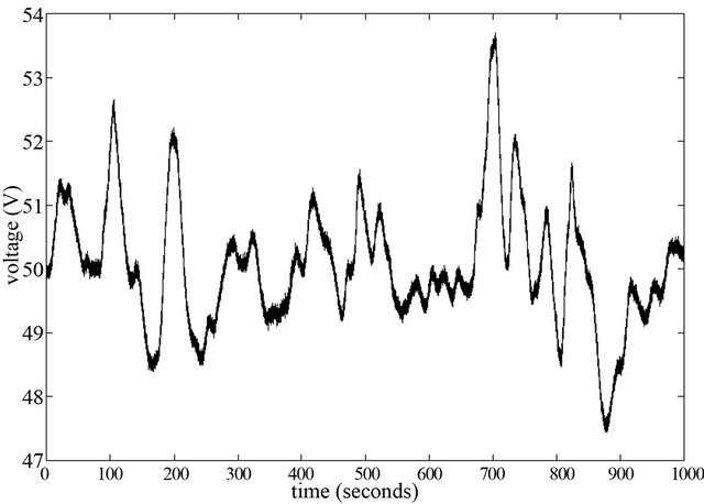
Figure 9. Ultracapacitor voltage (measured).
5. Further Considerations
The experimental results shown in Figures 8-10 are somewhat limited in that they provide only a snapshop of the conditioner’s behavior. To fully explore the conditioner’s capabilities in a variety of situations, a simulation of the conditioner was developed and a variety of wind speeds and charge/discharge situations were tested.
5.1. Wind Speed Simulation
Wind variability is frequently modeled as having a Weibull probability distribution function (as shown in Figure 11) [16]:
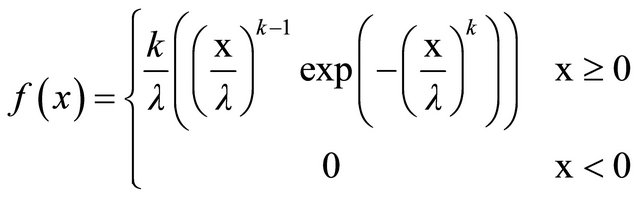 (2)
(2)
where  is the scale factor and
  is the shape factor. In wind applications,
  can range from 1 to 2.5, with regions with low wind having smaller
  factors. In our system, we chose
  to best match measured wind speeds locally. The performance characteristic of the Skystream3.7 is shown in Figure 12 [17].
5.2. Increasing Wind Speeds
The first trial considers the case in which the wind speed
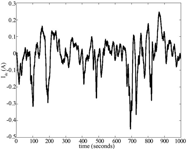
Figure 10. Ultracapacitor current (measured).
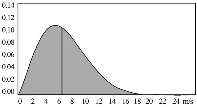
Figure 11. Windspeed with Weibull distribution.
slowly increases from zero to rated speeds over the time interval of two hours (7200 seconds). This case is intended to show the behavior of the ultracapacitor voltage and current in this situation. Note that the mean voltage change over the course of the two hours is nearly zero. This is to be expected because the mean of the filtered line current should be the same as the mean of the raw line current over long periods.
The currents and UCAP voltage is shown in Figures 13 and 14.
5.3. Decreasing Wind Speeds
The second case considers the situation in which the
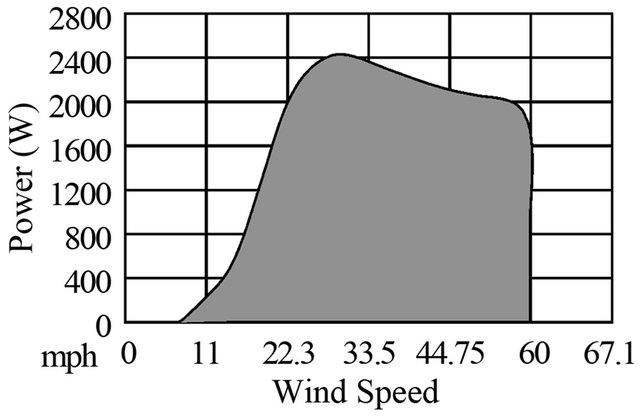
Figure 12. Skystream3.7 wind turbine performance.
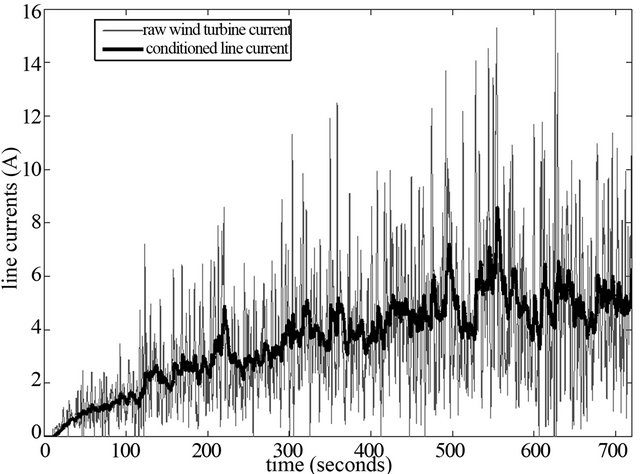
Figure 13. Line currents under increasing wind speeds.
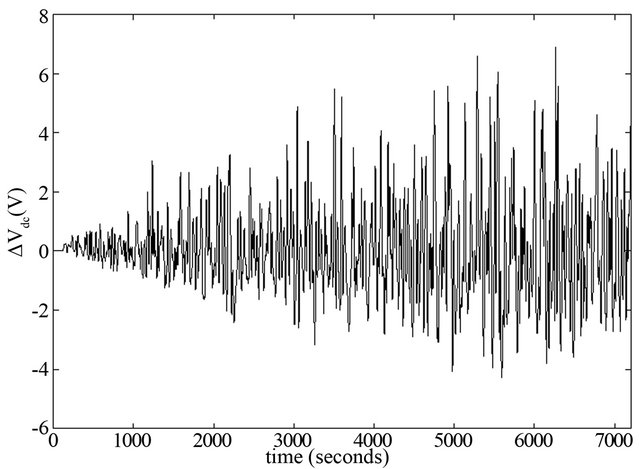
Figure 14. Change in ultracapacitor voltage with increasing wind speeds.
wind speed slowly decreases to zero over the time interval. Note that the mean voltage change over the course of the two hours is nearly zero. The currents and UCAP voltage is shown in Figures 15 and 16.
5.4. Discussion
The simulation results indicate that the proposed controller will work well under steady, increasing, and decreasing wind speeds. The selection of the filtered line current reference guarantees that the ultracapacitor will not charge or discharge beyond its operating range since the average of the filtered and raw line currents are the same over long periods of time. The injected or absorbed ultracapacitor current does not exceed the maximum allowable ultracapacitor at any time, thus the ultracapacitor is well-suited to this application.
6. Conclusion
This paper provided the schematic of an ultracapacitor-based smoothing circuit to condition wind turbine line currents. This controller would find application in
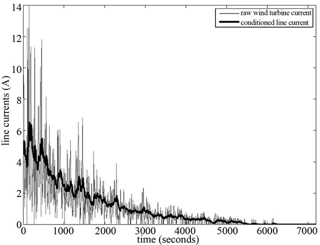
Figure 15. Line currents under decreasing wind speeds.
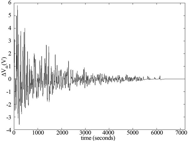
Figure 16. Change in ultracapacitor voltage with decreasing wind speeds.
situations in which rapidly varying currents may cause poor performance of loads such as pumps, induction motors, electronics, etc. in weak distribution systems. The ultracapacitor was sized to connect to the PCC without the need for a transformer. The DC-DC converter was designed to hold the dc-link capacitor of the voltage source converter near constant to provide good controllability. The proposed conditioner was validated in both experiment and simulation for a variety of conditions.
7. Acknowledgements
The authors gratefully acknowledge the support of the DOE Energy Storage Program through Sandia National Laboratories under BD-0071-D. Sandia is a multi-program laboratory operated by Sandia Corporation, a Lockheed Martin Company, for the United States Department of Energy’s National Nuclear Security Administration, under contract DE-AC04-94AL85000.
REFERENCES
- P. F. Ribeiro, B. K. Johnson, M. L. Crow, A. Arsoy and Y. Liu, “Energy Storage Systems for Advanced Power Applications,” Proceedings of the IEEE, Vol. 89, No. 12, 2001, pp. 1744-1756. doi:10.1109/5.975900
- M.-S. L. Lu, C.-L. Chang, W.-J. Lee and W. Li, “Combining the Wind Power Generation System With Energy Storage Equipment,” IEEE Transactions on Industry Applications, Vol. 45, No. 6, 2009, pp. 2109-2115.
- C. Abbey and G. Joos, “Supercapacitor Energy Storage for Wind Energy Applications,” IEEE Transactions on Industry Applications, Vol. 43, No. 3, 2007, pp. 769-776. doi:10.1109/TIA.2007.895768
- W. Li, G. Joos and J. Belanger, “Real-Time Simulation of a Wind Turbine Generator Coupled with a Battery Supercapacitor Energy Storage System,” IEEE Transactions on Industrial Electronics, Vol. 57, No. 4, 2010, pp. 1137- 1145.
- G. Mandic and A. Nasiri, “Modeling and Simulation of a Wind Turbine System with Ultracapacitors for ShortTerm Power Smoothing,” Proceedings of the 2010 International Symposium on Industrial Electronics, Bari, 4-7 July 2010, pp. 2431-2436. doi:10.1109/ISIE.2010.5637540
- E. Naswali, C. Alexander, H.-Y. Han, D. Vaniaux, A. Bistrika, A. von Jouanne, A. Yokochi and T. Brekken, “Supercapacitor Energy Storage for Wind Energy Integration,” Proceedings of the 2011 Energy Conversion Congress and Exposition, Phoenix, 17-22 September 2011, pp. 298-305. doi:10.1109/ECCE.2011.6063783
- L. Qu and W. Qiao, “Constant Power Control of DFIG Wind Turbines with Supercapacitor Energy Storage,” IEEE Transactions on Industry Applications, Vol. 47, No. 1, 2011, pp. 359-367. doi:10.1109/TIA.2010.2090932
- C.-C. Hua and C.-C. Tu, “Design and Implementation of Power Converters for Wind Generator,” Proceedings of the IEEE Industrial Electronics and Applications Conference, Sapporo, 21-24 June 2010, pp. 323-328.
- M. S. A. Dahidah, N. Mariun, S. Mahmod and N. Khan, “Single Phase Active Power Filter for Harmonic Mitigation in Distribution Power Lines,” National Power Engineering Conference, Bangi, 15-16 December 2003, pp. 359-362.
- L. Shi and M. L. C. Crow, “Comparison of Ultracapacitor Electric Circuit Models,” Proceedings of the 2008 IEEE PES General Meeting, Pittsburgh, 20-24 July 2008, pp. 1-6.
- “Maxwell Technologies.” http://www.maxwell.com/products/ultracapacitors/docs/datasheet_48v_series_1009365.pdf
- R. W. Erickson and D. Maksimovic, “Fundamentals of Power Electronics,” Kluwer Academic Publishers, New York, 2000.
- P. K. Krein, “Elements of Power Electronics,” Oxford University Press, New York, 1998.
- H. Akagi, “New Trends in Active Filters for Power Conditioning,” IEEE Transactions on Industry Applications, Vol. 32, No. 6, 1996, pp. 1312-1322. doi:10.1109/28.556633
- T. Kai and A. Tanaka, “A New Smooth Scheme for Power Fluctuation Using Inverter of Wind Power Generation with Doubly Fed Induction Generator,” Proceedings of the IEEE Electrical Machines and Systems International Conference, Calgary, 17-20 October 2008, pp. 2390- 2395.
- T. Burton, D. Sharpe, N. Jenkins and E. Bossanyi, “Wind Energy Handbook,” Wiley, Chichester, 2001. doi:10.1002/0470846062
- S. Windpower, “Optimum Energy in High Wind Environments.” www.windenergy.com
NOTES
*Corresponding author.