Communications and Network
Vol.5 No.3(2013), Article ID:35663,4 pages DOI:10.4236/cn.2013.53030
Automated Routing Control System of Local Area Network Segment
Computer Science Department, King Saud University, Riyadh, Saudi Arabia
Email: zalmakhadmee@ksu.edu.sa
Copyright © 2013 Zafer Al-Makhadmee. This is an open access article distributed under the Creative Commons Attribution License, which permits unrestricted use, distribution, and reproduction in any medium, provided the original work is properly cited.
Received April 10, 2013; revised May 15, 2013; accepted June 10, 2013
Keywords: City Network; Routing Control System; Vector Analysis; Traffic Metering
ABSTRACT
Automated Routing Control System supersedes the prior approach to LAN redundancy which provides two or more LANs and each has a network (LAN) controller coupled to data communication devices. Devices require some software to switch between the network (LAN) controllers to counter some network segment failures. This approach is proven to be very costly due to demands for “off-the-shelf” data communication devices with built-in LAN controller drivers [1]. Automated Routing Control System, is the ultimate solution to the growing demands for inexpensive (less costly) and less difficult approach which requires less modification rather than upgrade of network devices yet it minimizes data and information exchange losses and interruptions caused by connection failures within the network and lessens the task of managing a complex network having many segments rather than subnets under a centralized monitoring and management. Automated Routing Control System rather than mechanism is a realistic approach applied to meet the ever growing demands for reliability, high efficiency and availability within data and information exchange networks.
1. Introduction
The local area network (LAN) is used for providing data communications between various data communication devices. Whenever high availability and efficiency are required, some mechanism needs to be incorporated into the LAN to reduce the probability of loss of data and interruption of data communications [2].
A prior art approach to LAN redundancy has been to provide two or more LANs, each having a LAN controller coupled to data communication devices. Some software is required in the data communication devices to switch between the LAN controllers when a failure occurs in some segments of the network. This approach has been proven to be very costly and difficult—especially when using off-the-shelf (rare and costly) data communication devices having built-in LAN controller drivers [3].
Thus, what needed is an inexpensive (less costly) and less difficult approach to LAN redundancy. In particular, it would be highly desirable if the inventive approach could be applied to off-the-shelf data communication devices without requiring significant modification of the hardware or software thereof. Ideally, the inventive approach should allow the LAN to operate without an interruption, following a single failure anywhere in the LAN system rather than the segment.
This demand calls for a less costly and realistic approach applied to meet the high efficiency and availability of LAN application without requiring use of the offthe-shelf data communications devices, each coupled with a LAN controller, introduces us to the topic of this research—Automated Routing Control System of LAN segment.
2. The Model of Automated Routing Control System
The structure of the managed network is presented on Figure 1.
This map corresponds to the routes between different subnets of the network and uses hybrid topology, where we have combination of the tree and mesh (particularly) topology.
This network can be in one of the following modes:
1) normal operating mode, when all communication channels work properly;
2) corrupted network, when one or more communication channels are corrupted—no communication between
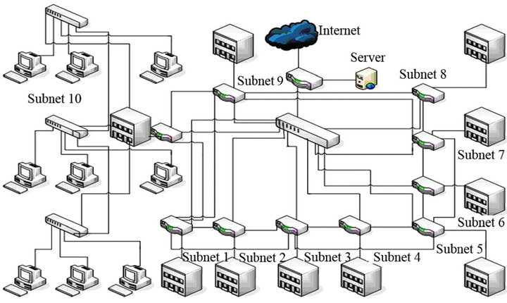
Figure 1. The network topology.
some subnets;
3) fixed mode, when communication between all subnets exists but current configuration of the network doesn’t correspond to production project.
First mode doesn’t demand additional explanation— structure of the network (hardware plus software) corresponds to the project.
Second mode corresponds to the situation when some subnets have no connection with one or more other subnets. It is possible in the case of:
1) transmitting media corruption;
2) concentrating hardware corruption (including—corruption of some single port or no electricity—Power failure);
3) software failure.
The third mode has properties:
1) hardware structure of the network corresponds to the project;
2) software structure doesn’t correspond to the project (has some differences);
3) data exchange between all subnets exists.
Therefore, the third mode is a result of the Automated Network Reconfiguring in the case of some accidental failure rather’ contingency appearing.
We are using vector analysis for the network model developments [4].
Physical connections between different nodes can be presented as matrix
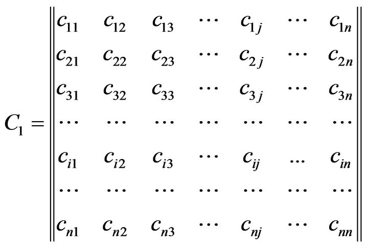 (1)
(1)
where —number of the subnets in the considered network;
 —binary parameter that can be determined as:
1) 1 if communication channel between subnets i and j exists;
2) 0 if communication channel between subnets i and j doesn’t exist.
The general model of the traffic inside a network can be presented in the matrix view
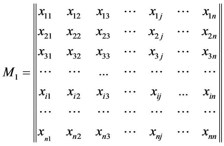 (2)
(2)
where  is the dimensionless variable that corresponds to the traffic volume between subnets i and j.
This value can be estimated on the basis of traffic volume and is determined from expression
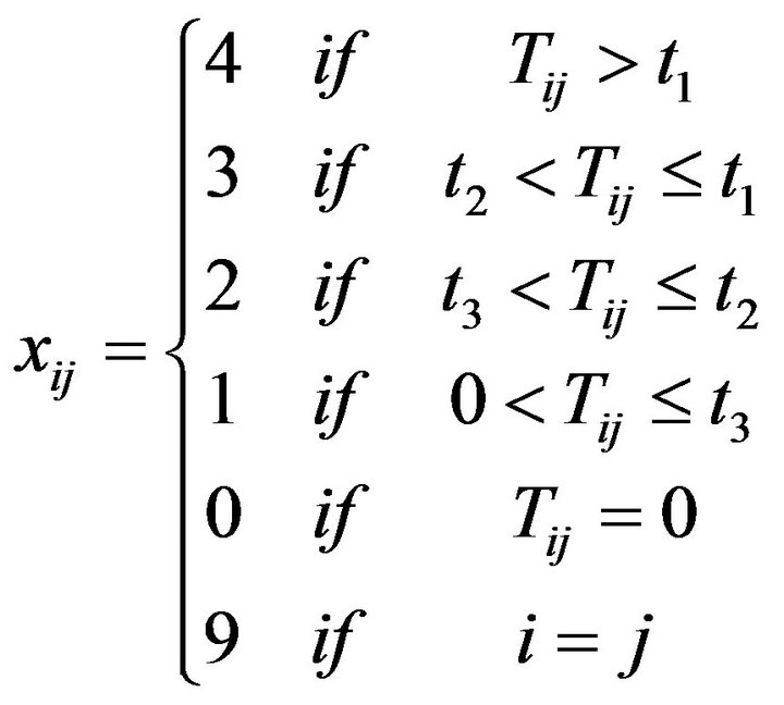 (3)
(3)
where t1 corresponds high traffic volume during considered time;
t2 and t3 correspond medium and low traffic volume correspondingly during considered time.
Therefore, the network is presumed to be working properly if traffic between any two subnets of the considered network is not equal to zero;
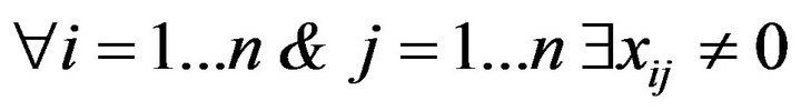 (4)
(4)
if the expression (4) is true we have no problem. However, if expression (4) is false, then we presume network failure hence talk about contingency manifest rather occurrence. It is the signal for beginning of processing of data with the purpose of not only detecting the fault fact but for localization of the fault.
The routing diagram of LAN has a view
 (5)
(5)
where —is parameter that determines presence of route between appropriate subnets; it is referred to as route presence. This parameter equals
 (6)
(6)
Additionally, we suppose that if route presence equals 1 therefore we have bidirectional routing: from subnet i to subnet j and from subnet j to subnet i.
The matrix (5) gives possibility to determine the route for data exchange between two subnets of network. It gives possibility to detect the place of possible transmitting line corruption or breakdown.
The condition of the normal network working is described by the following formula
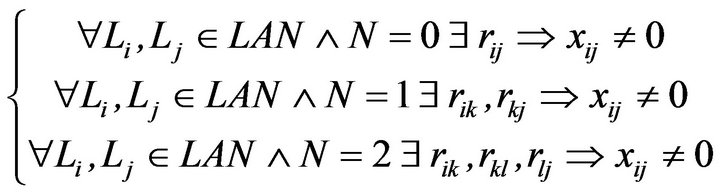 (7)
(7)
where —number of the intermediate routing points between subnets i and j.
Model of system uses additional matrix
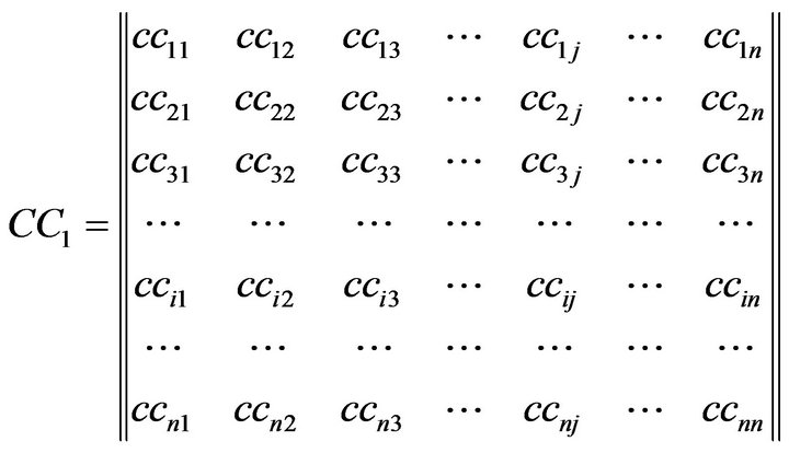 (8)
(8)
where —binary parameter that can be determined as:
1) 1 if communication channel between subnets i and j is not corrupted;
2) 0 if communication channel between subnets i and j doesn’t exist, it is corrupted.
After fixing of problem matrix (8) must be restored to the original view (all elements must be 1).
This matrix stores data about corrupted connections in the network (the nature of the corruption doesn’t matter).
If we have the corruption of the connection ( ) the system makes changes in the matrix (8)
 (9)
(9)
Hence, the system marks appropriate node as not usable. We can’t change the interconnection Figure 1 because it is necessary to restore it after fixing of the problem. But this node should be unusable temporarily before its fixing.
Expressions (10) and (11) are analogous rather similar to expression (9) for other cases: 1 or 2 intermediate routing points correspondingly
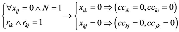 (10)
(10)
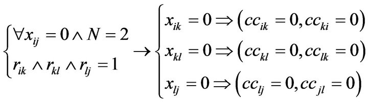 (11)
(11)
The developed model gives possibility to provide effective management of the city network which is considered in the current work. It can be realized using WEB based Database Management System, which must satisfy additional demands:
1) minimal cost;
2) routing hardware location—common use rooms.
It makes some limitations on the hardware using. Really we need use small and cheap routing devices, which can be located in the public use places like stairwells etc.
We can’t use personal computers for that. Using of the expensive routing switches has no sense too.
Therefore our task is to use the most simple and cheap devices.
3. Automated Routing System Development
Result of the Automated Routing Control System of Local Area Network Segment is implemented in the view of WEB-based system, which executes next functions:
1. connectivity:
a) monitoring;
b) structure upgrading;
2. fault Detection:
a) traffic metering;
b) traffic logical model;
3. network configuring:
a) physical connections;
b) routing map;
c) corrupted connections;
4. software (application) testing:
a) events;
b) reset tables;
5. network physical structure display:
a) the routing table display;
b) the fault display;
c) the current state display;
d) the project of decision display;
6. registering of all events in the network.
Example of the screen form is shown in Figure 2.
4. Conclusion
Based on this information, there is a growing need for reliable, highly available and efficient means of communication rather than information exchange hence data ex-
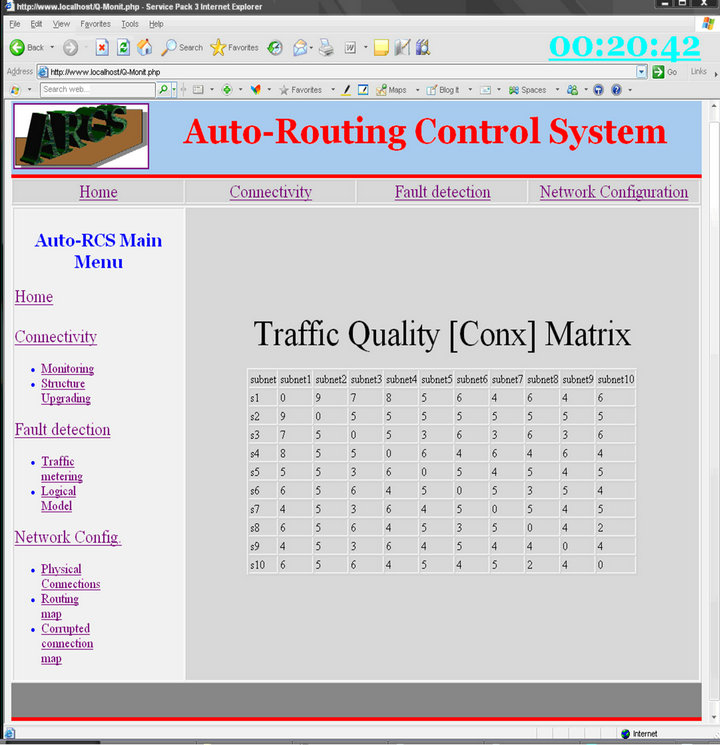
Figure 2. Example of the program screen form.
change and sharing of resources over communication networks, Automated Routing Control system rather than mechanism needs to be incorporated into the network to reduce the probability of loss of data and interruptions of information exchange. Automated Routing Control System supersedes the prior approach to LAN redundancy which provides two or more LANs and each has a network (LAN) controller coupled to data communication devices. Devices require some software to switch between the network (LAN) controllers to counter some network segment failures. This approach is proven to be very costly due to demands for “off-the-shelf” data communication devices with built-in LAN controller drivers [1]. Automated Routing Control System, is the ultimate solution to the growing demands for inexpensive (less costly) and less difficult approach which requires less modification rather than upgrade of network devices yet it minimizes data and information exchange losses and interruptions caused by connection failures within the network. Precisely, Automated Routing Control System rather than mechanism is a realistic approach applied to meet the ever growing demands for reliability, high efficiency and availability within data and information exchange networks.
REFERENCES
- L. L. Peterson and B. S. Davie, “Computer Networks: A Systems Approach,” 3rd Edition, the Morgan Kaufmann Series in Networking, Burlington, 2007.
- D. E. Comer, “Computer Networks and Internets,” 5th Edition, Addison-Wesley, Boston, 2008.
- J. Radz, , “Fundamentals of Computer Network Analysis and Engineering: Basic Approaches for Solving Problems in the Networked Computing Environment,” iUniverse, Bloomington, 2005.
- M. Hutton, “Vector Analysis Notes,” 2006.